Sunday, August 31, 2008
Display problem ? Click HERE
Recommended :
- Subscribe FREE - Chemical Engineering
- Tips on Succession in FREE Subscription

Several concerns & recommendations on Pressure Relief Valve (PSV) discharge line has been discussed in "Few Concerns & Recommendations of PSV Discharge Tail pipe". Subsequent to this posting, questions has been raised on the PSV Inlet line.
What are the concerns & recommendation on the PSV inlet line ?
- Subscribe FREE - Chemical Engineering
- Tips on Succession in FREE Subscription
Several concerns & recommendations on Pressure Relief Valve (PSV) discharge line has been discussed in "Few Concerns & Recommendations of PSV Discharge Tail pipe". Subsequent to this posting, questions has been raised on the PSV Inlet line.
What are the concerns & recommendation on the PSV inlet line ?
Issue relates to PSV Inlet Line
Let see those issue relates to PSV inlet line :
- First far most important is undersized PSV inlet line results excessive inlet line frictional loss (non-recoverable line loss) and leads to PSV chattering. Repetitive and rapid reciprocating disc knock on the valve seat may damage PSV disc & valve seat, severe vibration and noise level.
- Excessive inlet line loss also lead to overpressure of protected equipment (which is exceeded the allowable by code)
- Low pocket due to inlet line routing would leads liquid accumulation. liquid accumulation would promote corrosion.
- Liquid accumulated in inlet piping due to incorrect routing. Whenever PSV is lifted, large vapor flow will put the liquid column (at very high velocity) will knock at the PSV disc and create severe surge (water hammer) and vibration to the PSV inlet line, outlet line and PSV itself. Surging and vibration may damage PSV and associated line.
- Large liquid column formed at the inlet to PSV (those elevated PSV will results overpressure of protected equipment.
- If solid present in fluid, there is potential of solid accumulated in low pocket and may lead to complete blockage of inlet line. This defeat the purpose of PSV.
- Excessive inlet line length and elbow increases line loss
- Present of devices i.e gate valve, reduced bore ball valve, butterfly valve (read more in "Should we install Butterfly valve for Pressure Relief Valve (PSV) isolation ?"), check valve, etc and/or fittings which having reduce flow path at the inlet line. Reduced flow path potentially increase line loss and causes problem associated with large inlet loss as discussed above. API RP 521 do not permit total cross sectional area (flow path) of valve or fitting less than total PSVs area.
- Isolation valve accidentally close by operator - potentially lead to overpressure of protected system
- Isolation valve at the inlet line lose may "self close" during relief or blowdown due to vibration. "Self-close" is high torque caused by asymmetric pressure distribution in the inner surface of isolation valve lead to self closure- potentially lead to overpressure of protected system. High torque may break normal duty locking plate of the valve.
- Inlet line expose to high pour point fluid, fluid may precipitate, crystallize or polymerize, etc, ambient cooling on stagnant fluid at inlet pipe may potentially precipitate/polymerize/crystallize/solidify at the inlet line (even though no low pocket) and reduce inlet line free flow path.
- Large pressure drop across PSV during relief would results fluid (downstream of PSV) temperature drop to subzero (due to JT effect). The inlet valve may possibly cooled to subzero due to heat conduction. Moisture content around inlet valve may form ice and cause the valve stuck at position.
After understand the potential issue related to inlet, there are few recommendations that may be considered for inlet line :
- Increases inlet line size, reduce number of elbows and fittings to minimize inlet line loss (non-recoverable loss). Ensure inlet line loss (non-recoverable loss) is maximum 3% of set pressure (as per API RP 521) except permitted by API RP 521 Part II, section 4.2.3 i.e. installation of pilot operated PSV. The inlet line loss shall be based on PSV rated flow.
- No pocket at the inlet line. A special note shall be indicated in the P&ID (generalized in legend)
- Do not installed valve, fitting or device with potential of internal failure i.e butterfly valve, check valve, etc
- Consider to install PSV with larger inlet flange to avoid high velocity of the inlet pipe (after reducer). Detail may refer to API Std 526
- Car Seal Open (CSO) or Locked Open (LO) of all manual isolation valve, unless required by safety analysis i.e HAZOP
- Remove handle to minimize the opportunity of operation of isolation valve and reduce potential of self closure of valve, unless required by safety analysis i.e. HAZOP
- If ball valve is installed, Full Bore (FB) ball valve to be used.
- When valve is locked by a locking plate, consider to install heavy duty locking plate to minimize potential of self-closure
- Consider to install valve with "high torque for closure" to minimize potential of self-closure
- Ensure valve vertically upward to minimize potential of self-closure
- Consider to use gate valve to minimize potential of self-closure, if it is inline with plant wide isolation philosophy
- If gate valve is used, ensure the valve stem and handle is at least 45deg incline downward to avoid blockage due failure of valve internal
- Relocate isolation valve away from PSV i.e. relocated valve to upstream of reducer may reduce the risk of self closure due high vibration.
- Ensure inlet pipe is self drained back to protected vessel or pipe to minimize potential of liquid present in inlet line
- Ensure flow path (cross sectional area) of inlet line is more than total cross sectional area of ALL PSVs area.
- For inlet line expose to high pour point fluid, fluid may precipitate, crystallize or polymerize, etc, consider to provide insulation of inlet line to minimize heat loss and precipitate / polymerize / crystallize / solidify.
- Subject to severity of ambient cooling and potential of precipitate / polymerize / crystallize / solidify, may consider heat trace the inlet line. Whenever heat trace in installed, the integrity and reliability of heat trace shall be ensured.
- For inlet line expose to high pour point fluid, fluid may precipitate, crystallize or polymerize, etc, the PSV tapping location shall be installed to minimize liquid / solid carry into the inlet line i.e. top of vessel instead of pipe. Read more in "Where to Locate the PSV Inlet Nozzle ?".
- Consider to provide Rupture disc (RD) upstream of PSV will avoid fluid contains substances possibly precipitate / polymerize / crystallize / solidify accumulate at the inlet nozzle and pipes. (Read more in Why Rupture (RD) Upstream of Pressure Relief Valve (PRV) ?"). In the event RD is provided upstream of PSV, consider to install device to identify the potential of RD. Read more recommendation in "Why Two Rupture Discs in Series ?"
- Provide vent connection between isolation valve and PSV for depressuring during maintenance.
PSV inlet line is simple, many issues still associate with design and installation in order to ensure a well designed overpressure protection system.
Thanks to JProcess who has provided some inputs to above article.
Related Posts
- Few Concerns & Recommendations of PSV Discharge Tail pipe
- Where to Locate the PSV Inlet Nozzle ?
- Is Single PSV Protection Sufficient ?
- PSV Chaterring is Destructive...The ways to Prevent...
- Relate PSV Relieving Flow to Stamped Capacity
- Thermal Relief of Non-Flashing Liquid in Pipe
Labels: Overpressure Protection, Pressure Relief Device
Saturday, August 30, 2008
Display problem ? Click HERE
Recently there are many new visitors accessing Chemical & Process Technology blog and many readers found some tips and tricks in post by author of Chemical & Process Technology blog. As they found this site is useful to them, the subscription to Chemical & Process Technology blog increases rapidly. Thanks to your support. If you think this blog is useful to some of your lovely friends, do let them aware of this site and give them a chance to grab one or two tips from Chemical & Process Technology blog.
In earlier post "Continuous Improvement of this blog & Promote Interaction", we have introduced some interaction features in this blog. Part of them are the
- "Outbrain" rating widget
- Comment column
- Email icon.
There are few additional benefits of commenting on the blog :
i) Your opinion will be published in this blog (if found relevant).
ii) Your opinion and comments will be addressed by us in this blog.
iii) Other readers may learn from your experiences and view points.
iv) Others who has similar experiences or experts in the similar field will jump in and provide their experiences as well. You and every reader will learn more.
v) If you have blog or website, you can link it to your blog and website. This will direct some visitors to your blog or website.
Then your experiences, every readers experiences and Chemical & Process Technology blog experiences will grow like ice ball rolling...
We strongly encourage you to comment in the blog post. Thanks again.
Related Topic
- Continuous Improvement of this blog & Promote Interaction
- 6 elements & factors lead to high quality question
- Carefully assess information in the web
Labels: General
Thursday, August 28, 2008
Display problem ? Click HERE
Recommended :
- Tips on Succession in FREE Subscription
- Subscribe FREE - Processing & Control News

There are many ways to obtain the Dynamic viscosity of water. You may use Steam table, Excel calculator using Water97_v13 add-in, Steam Calculator (web), SteamTab program, simulator like HYSYS, etc. All above required you to have the material on hand.
Following is a simple equation to estimate the Dynamic Viscosity of Water. It is easy to be written in your notebook or memorize.
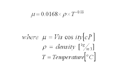
*Applicable in water temperature of 25-250 degC
Earlier post "Conduct Steam-Water Balance MANUALLY using Water97_v13" has discussed the Dynamic Viscosity can be extracted using a special function, viscW(T,P) in Excel Add-on in (Water97_v13.xla or Alternative download). The dynamic viscosity of water at different temperature from 30 to 250 degC (at 40 barg) have been predicted using Water97_v13.xla and Dynamic Water Viscosity formula . Results tabulated as follow :
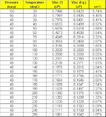
The error is 01-3.5% with maximum 5.75% at low temperature. It is consider rather sufficient from engineering perspective and pretty useful when you have nothing on hand.
Related Topic
Earlier post "Conduct Steam-Water Balance MANUALLY using Water97_v13" has discussed the Dynamic Viscosity can be extracted using a special function, viscW(T,P) in Excel Add-on in (Water97_v13.xla or Alternative download). The dynamic viscosity of water at different temperature from 30 to 250 degC (at 40 barg) have been predicted using Water97_v13.xla and Dynamic Water Viscosity formula . Results tabulated as follow :
The error is 01-3.5% with maximum 5.75% at low temperature. It is consider rather sufficient from engineering perspective and pretty useful when you have nothing on hand.
Related Topic
- Conduct Steam-Water Balance MANUALLY using Water97_v13
- SteamTab - A simple Executable file for Steam - Water Properties...
- Useful Steam - Condensate Calculator
- Steam - Condensate Useful Links...
- Square-root-Square-root Formula Ease Saturated Steam-Codensate Temperature Prediction
- Steam in FIRE...
- "Fire from Ice"...
Labels: Rule-Of-Thumb, Steam
Wednesday, August 27, 2008
Display problem ? Click HERE
Recommended :
- Tips on Succession in FREE Subscription
- Subscribe FREE - Processing & Control News
"I was doing Depressuing using HYSYS and flare network back pressure calculation using FLARENET for conventional Blowdown valves with restriction (BDV/RO). Peak flow of Depressuring unit in HYSYS which obtained from initial depressuring and based on initial depressuring pressure to Atmospheric pressure, is used as input to FLARENET.
- Tips on Succession in FREE Subscription
- Subscribe FREE - Processing & Control News
"I was doing Depressuing using HYSYS and flare network back pressure calculation using FLARENET for conventional Blowdown valves with restriction (BDV/RO). Peak flow of Depressuring unit in HYSYS which obtained from initial depressuring and based on initial depressuring pressure to Atmospheric pressure, is used as input to FLARENET.I have two questions :
What I really concerned is back pressure calculated from FLARENET is higher than ATM, is the back pressure will affect the peak flow ?
What I had done for those cases is to assume a back pressure in HYSYS to calculate the peak flow and input it into FLARENET. Newly calculated back pressure from FLARENET will be re-enter into HYSYS depressuring unit to recalculate new peak flow in HYSYS. Above will be iterated until both of back pressure and peak flow are match in HYSYS and FLARENET. Am i in right track ?"
Above was a question raised by an engineer who was conducting plant blowdown and flare network studies.
First far most important thing is that there will be total plant or segregated zone blowdown. This type of blowdown will results simultaneous opening of all BDVs within a zone and simultaneous blowdown of multiple sections. One shall not consider SINGLE BDV opening ONLY. Simultaneous blowdown will results high total blowdown rate and induced high back pressure to each BDV / RO within the blowdown zone.
In many events, the flow passing the RO is CRITICAL flow where the back pressure from flare network is lower than the fluid critical pressure (Pc). Read more in "A refresh to Process Engineer on few phenomenons in restriction orifice". Under critical flow condition, the back pressure has no impact to the flow rate passing through the RO (assume backpressure does not affect the vena contracta cross sectional area). Thus, peak flow calculated in HYSYS depressuring unit considering backpressure of ATM is still remain same if the backpressure (Pb) is lower than critical pressure (Pc).
 However, for many rare cases when the system pressure is low, hence the critical is much lower. This potentially results back pressure high than critical pressure and cause SUBCRITICAL flow condition. Under this condition, backpressure has impact to the peak flow calculated by HYSYS.
Knowing back pressure may affect peak flow under subscritical flow condition, some level of checking and iteration may required.
Iteration as proposed above could be very time consuming and not all the BDV/RO required iterate update. Infact only those BDV/RO experiencing Subcritical flow would need to involve in the iteration process.
The following steps may be considered :
i) For initial step, use ATM in HYSYS for depressuring to estimate the peak flow
ii) Peak flow estimated in HYSYS will be entered into FLARENET to calculate back pressure at each BDV/ROs.
iii) Compare each BDV/RO Critical pressure (Pc) and Back pressure (Pb). If Pc is higher than Pb, that particular BDV/RO need not involve in the iteration.
iv) Identify those BDV/RO with Pc less than Pb. Re-adjust back pressure in HYSYS base on calculated Pb from FLARENET to obtain a new peak flow.
v) Reenter and rerun in FLARENET.
vi) Repeat step (iii) to (v) till backpressure in HYSYS and FLARENET are matched.
Above will significantly reduce the iteration time.
Related Topic
First far most important thing is that there will be total plant or segregated zone blowdown. This type of blowdown will results simultaneous opening of all BDVs within a zone and simultaneous blowdown of multiple sections. One shall not consider SINGLE BDV opening ONLY. Simultaneous blowdown will results high total blowdown rate and induced high back pressure to each BDV / RO within the blowdown zone.
In many events, the flow passing the RO is CRITICAL flow where the back pressure from flare network is lower than the fluid critical pressure (Pc). Read more in "A refresh to Process Engineer on few phenomenons in restriction orifice". Under critical flow condition, the back pressure has no impact to the flow rate passing through the RO (assume backpressure does not affect the vena contracta cross sectional area). Thus, peak flow calculated in HYSYS depressuring unit considering backpressure of ATM is still remain same if the backpressure (Pb) is lower than critical pressure (Pc).
However, for many rare cases when the system pressure is low, hence the critical is much lower. This potentially results back pressure high than critical pressure and cause SUBCRITICAL flow condition. Under this condition, backpressure has impact to the peak flow calculated by HYSYS.Knowing back pressure may affect peak flow under subscritical flow condition, some level of checking and iteration may required.
Iteration as proposed above could be very time consuming and not all the BDV/RO required iterate update. Infact only those BDV/RO experiencing Subcritical flow would need to involve in the iteration process.
The following steps may be considered :
i) For initial step, use ATM in HYSYS for depressuring to estimate the peak flow
ii) Peak flow estimated in HYSYS will be entered into FLARENET to calculate back pressure at each BDV/ROs.
iii) Compare each BDV/RO Critical pressure (Pc) and Back pressure (Pb). If Pc is higher than Pb, that particular BDV/RO need not involve in the iteration.
iv) Identify those BDV/RO with Pc less than Pb. Re-adjust back pressure in HYSYS base on calculated Pb from FLARENET to obtain a new peak flow.
v) Reenter and rerun in FLARENET.
vi) Repeat step (iii) to (v) till backpressure in HYSYS and FLARENET are matched.
Above will significantly reduce the iteration time.
Related Topic
- Don't misunderstood depressuring
- Depressuring within 15 minutes no longer applicable ?
- Bug in ASPENTECH HYSYS 2006 Dynamic Depressuring Fisher Valve model
- Controlled and Non-controlled Type Depressuring
- How to apply valve equation in HYSYS Depressuring ?
- How to determine if a restriction orifice will experience cavitation ?
Labels: Depressurization, HYSYS, Process simulation
Display problem ? Click HERE
Recommended :
- Tips on Succession in FREE Subscription
- Subscribe FREE - Recycling Today

Now you may have your own fuel filling station in your garage. You may brew your own ethanol from beets, corn, sugar cane, alcohol, leftover beer, wine, booze, etc. Produced ethanol will be stored and ready to mix with gasoline in your car gasoline tank. Together with the E-fuel carbon credit program, it is cost saver which possibly reduce the cost down to US$0.1 - US$1.0 per gallon of fuel. Apart from fuel cost reduction, ethanol also reduces C02 emissions by 85% when used in vehicles in place of gasoline. This significant helps to reduce greenhouse effect and global warming.

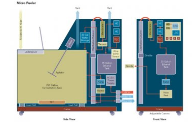
E-Fuel 100, a self-contained ethanol micro-refinery will produce ethanol to top up their gasoline tank with the aim to reduce fuel cost. E-Fuel is typically conventional alcohol brewing unit which consists of fermentation unit, distillation unit, condensation unit, storage and pumping unit and control unit.
With high energy price and tremendous pressure on pushing environmental friendly green technology, this E-fuel invention is expected to gain serious attention from consumer and law maker.
Source : "Ethanol Is The New Homebrew", Design News
Related Topic
- Tips on Succession in FREE Subscription
- Subscribe FREE - Recycling Today
Now you may have your own fuel filling station in your garage. You may brew your own ethanol from beets, corn, sugar cane, alcohol, leftover beer, wine, booze, etc. Produced ethanol will be stored and ready to mix with gasoline in your car gasoline tank. Together with the E-fuel carbon credit program, it is cost saver which possibly reduce the cost down to US$0.1 - US$1.0 per gallon of fuel. Apart from fuel cost reduction, ethanol also reduces C02 emissions by 85% when used in vehicles in place of gasoline. This significant helps to reduce greenhouse effect and global warming.
E-Fuel 100, a self-contained ethanol micro-refinery will produce ethanol to top up their gasoline tank with the aim to reduce fuel cost. E-Fuel is typically conventional alcohol brewing unit which consists of fermentation unit, distillation unit, condensation unit, storage and pumping unit and control unit.
With high energy price and tremendous pressure on pushing environmental friendly green technology, this E-fuel invention is expected to gain serious attention from consumer and law maker.
Source : "Ethanol Is The New Homebrew", Design News
Related Topic
Labels: Global warming, Green Technology, Greenhouse Effect
Tuesday, August 26, 2008
Display problem ? Click HERE
In earlier post "Carefully assess information in the web", it is advised that information in internet shall be used with care. A few emails have been send to us to share AIR dew point curve.
Following is an AIR dew point curve. The intention is just to make it handy to everyone.
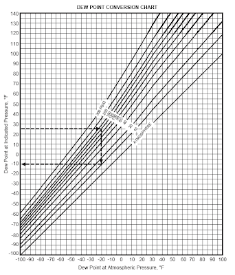
One of typical usage of this curve is to find the dew point of air at required pressure level (P1) when you already aware of dew point at different pressure level (P0).
Example
What is the air dew point at 10 psig (P1) if the dew point at the air dryer outlet is 25 degF at 125 psig (P0) ?
Above curve is self-explained. The air dew point at 10 psig is -10 degF.
Related Topic
- Air Receiver - Doubt on SCFM & CFM
- Heat Transfer Coefficient For Air-Cooled Heat Exchangers
- A few means to avoid hydrate formation downstream of air cooler...
- Carefully assess information in the web
- Air Pollution Control & Tail Gas Treatment
- Useful Documents Related to Cooling Tower
- Steam - Condensate Useful Links...
- FREE & Reliable Control Valve Sizing Software
- FREE & reliable Pressure Relief Valve Sizing Software
Labels: Air
Monday, August 25, 2008
Display problem ? Click HERE
Recommended :
- Tips on Succession in FREE Subscription
- Subscribe FREE - Hydrocarbon Engineering
 A pressure relief valve (PSV) protecting a pressure containing system, it is possibly be tapped from a vessel or piping. The location of the tapping is very much subject to the source of overpressure, flow path of the fluid, fluid quality, etc.
Top of Vessel
A PSV protecting a vessel generally located on the highest location of the vessel. The intention is to minimize potential of liquid get into the inlet line and subsequently passing the PSV. Present of liquid in PSV throat will potentially limit the flow path of a the PSV and lead to overpressure.
Apart, as fluid is entering a vessel during overpressure and PSV lift, fluid may carry some liquid and solid will slow down when it enter the vessel. It potential partial knock out liquid and solid in the vessel and avoid carry into the PSV.
Vapor Outlet Pipe (Highest point)
Sometime PSV is tapped from the vapor outlet piping. One of the advantage is it located on the highest point of the system and minimize the potential of liquid entering PSV which may reduce the vapor flow path. Another advantage is reduce number of nozzle located on the vessel. One of the downside the locating PSV on the vapor outlet is additional service platform and structure required dedicated to these PSVs. It would increases the installation cost.
Side of Vessel
Present of internal i.e. demister in a vessel, the tapping point would possibly be located at the side of the vessel but below the demister. This is to avoid the potential of demister blockage and limiting flow passing demister where it possibly cause overpressure of compartment upstream of demister (lower compartment) while downstream of demister may possibly operate at pressure below set pressure. Apart, it may also cause PSV chattering due to large pressure drop across demister.
Present of solid particle in fluid and clear flow path in demister would be the determining factors. However, one may have to understand very low possibility to have a complete blockage of demister and demister is still mechanically fitted on the vessel when exposing to large differential pressure. Thus in many occasion, this could be an issue with long debate and it end up one PSV at lower compactment of demister to protect vessel from process upset whilst another PSV located on the vessel top protect vessel upper compartment from fire contingency.
Another issue related to vessel side tapping is it reduce the distance between PSV inlet nozzle and liquid level in the vessel. Dynamic turbulence and vapor movement may result severe entrainment and lead to large amount of liquid enters PSV. Again it reduce the flow path of PSV.
Inlet of Vessel
Separator inlet nozzle may be fitted with inlet device. The may potential cause partial blockage and lead to overpressure of section upstream of feed nozzle. Thus, a PSV may be tapped from the inlet of vessel. While considering PSV tap from inlet pipe, one may understand liquid (and solids) can be easily carried into PSV.
Concluding Remarks
PSV tapping location is significant affect the performance of the PSV. Proper location may sometime determining the effectiveness of an overpressure protection system. Extra care shall be paid into this aspect.
Related Posts
Related Posts
- Is Single PSV Protection Sufficient ?
- Few Concerns & Recommendations of PSV Discharge Tail pipe
- Concerns & Recommendations on PSV INLET line
- PSV Chaterring is Destructive...The ways to Prevent...
- Is PSV tail pipe & lateral at CHOKED (Mach no = 1) Accpetable ?
- How Back Pressure Affect Conventional PSV Set Pressure Subject to It Vent
Labels: Overpressure Protection, Pressure Relief Device
Sunday, August 24, 2008
Display problem ? Click HERE
Recommended :
- Subscribe FREE - Processing Magazine
- Tips on Succession in FREE Subscription

A pressure vessel designed according to ASME Section 8, Div II, pressure relief valve (PSV) shall be provided to protect the vessel from overpressure caused by process failure and fire contingency. However, there is not further discussion if number of PSV. Now the question is provision of single PSV is sufficient ?
One of the way to assess if provision of single PSV is sufficient is to study the Safety Integrity Level (SIL) demand by the system and what the SIL level of protection system provided. Prior to the assessment, the Safety Integrity Level (SIL), Probability to Failure on Demand (PFD) and the relationship shall be understood.
Safety Integrity Level (SIL)
Safety Integrity Level (SIL) is a simple measurement of the performance of relative risk-reduction level for a Safety Instrumented Function (SIF).
Probability to Failure on Demand (PFD)
Probability to Failure on Demand (PFD) is a reliability measurement of likelihood to fail when it is requested to perform.
Relation Between SIL & PFD
The following tabulate the relationship between SIL and PFD according to IEC61508 and ISA S84.
| SIL - IEC 61508 | SIL - ISA S84 | PFD |
| 1 | 1 | 0.1 - 0.01 |
| 2 | 2 | 0.01 - 0.001 |
| 3 | 3 | 0.001 - 0.0001 |
| 4 | - | 0.0001 - 0.00001 |
Reliability of PSV
The reliability of PSV is subject to type of PSV and how it work. More complicated and more parts involve in single performance would increase the PFD of the device and reduce the SIL can be provided by itself. From "Guidelines for Process Equipment Reliability Data" by Center for Chemical Process Safety (CCPS), the PFD for conventional spring loaded PSV and Pilot operated PSV as follow :
Table : PFD for PSVs
| PSV Type | PFD Lower | PFD Mean | PFD Upper | SIL Provided |
| Spring Loaded | 7.9E-06 | 2.12E-04 | 7.98E-04 | 3 |
| Pilot Operated | 9.32E-06 | 4.15E-03 | 1.82E-02 | 2 |
Example
In one of the previous project, a Pressure Relief Valve (PSV) is provided to protect a pressure contained system. The PSV is conventional spring loaded type. During Instrumented Protective System (IPF) meeting section, a question raised. The Safety Integrity Level (SIL) required by the plant is SIL-2. apart from High-High pressure trip (PAHH), is provision of single PSV protecting the system is sufficient ?
As a conventional spring loaded PSV can deliver SIL-3, single PSV would be sufficient.Related Topics
- Parallel Valve Technology Increase Safety & Reduce Nuisance Trips
- Dust Explosion Basic & Protection
- Requirements of SDV Bypass Pressurization Line
- Partial Stroke Testing for Emergency Shutdown Valves
- 12 Features required for Shutdown Valve (SDV)
- Workbook for Chemical Reactor Relief System Sizing
- A must have book...Emergency Relief System Design Using DIERS Technology
- Matcor: Put safety first, and profits will follow
Labels: Safety
Display problem ? Click HERE
Recommended :
- Subscribe FREE - Chemical Processing
- Tips on Succession in FREE Subscription
 Heating system is one of the common utilities in a gas processing, LNG production, refining plant, etc. Heating medium commonly used are Heating oil, thermal fluid, water, etc. In circulating thermal-fluid heating systems, the heat transfer rate is typically controlled to maintain a desired outlet-temperature setpoint of the fluid. However, it is the temperature of the fluid film in contact with the heater walls instead of bulk fluid temperature that often is the key factor affecting fluid life, system fouling, and overall equipment performance.
CE and Solutia are organizing a webinar on Heat Flux & Film Temperature. The webinar presenter is Robert Pelini, P.E., President of RGP Engineering, LLC. who has more than 24 years experience in the design of fired heaters and heat recovery systems and has authored numerous technical articles and
publications on process equipment and energy systems design.
 The webinar will discuss :
- Subscribe FREE - Chemical Processing
- Tips on Succession in FREE Subscription
Heating system is one of the common utilities in a gas processing, LNG production, refining plant, etc. Heating medium commonly used are Heating oil, thermal fluid, water, etc. In circulating thermal-fluid heating systems, the heat transfer rate is typically controlled to maintain a desired outlet-temperature setpoint of the fluid. However, it is the temperature of the fluid film in contact with the heater walls instead of bulk fluid temperature that often is the key factor affecting fluid life, system fouling, and overall equipment performance.CE and Solutia are organizing a webinar on Heat Flux & Film Temperature. The webinar presenter is Robert Pelini, P.E., President of RGP Engineering, LLC. who has more than 24 years experience in the design of fired heaters and heat recovery systems and has authored numerous technical articles and
publications on process equipment and energy systems design.
- The importance of fluid film temperature
- Variables that affect film temperature, with specific emphasis on heat flux at the metal surfaces
- Various types of fired and electric thermal fluid heater designs and estimation of their heat flux rates
- Heat flux rates in convective thermal fluid heaters
- How to estimate or check peak fluid film temperature
- Common problems and how to avoid them
- Therminol Reference Disk - Assist you to Optimize your Heat Transfer System
- FAYF - Heat Transfer - Useful Heat Transfer Equation
- Heat Transfer - Internal and External Flow
- FREE E-book........A Heat Transfer Textbook
- Few Tips on Energy Efficient & Recovery
- Heat Transfer Coefficient For Air-Cooled Heat Exchangers
- COLLECTION of Typical Overall Heat Transfer Coefficient (U-factor)
Labels: Heat Transfer
Thursday, August 21, 2008
Display problem ? Click HERE
Recommended :
- Subscribe FREE - World Pumpv (USA & Europe only)
- Tips on Succession in FREE Subscription
The discussion on pump cavitation have been circulated around what is pump cavitation ? how destructive a cavitation ? how cavitation sound & looks like ? what the relationship between NPSHa & NPSHr ? how to increases NPSHa to minimize / avoid cavitation ?... We understood that a minimum flow shall be maintained to minimize cavitation, avoid impeller damage and extend pump lifespan. "Rule-of-thumb For Minimum Flow Recycle" discussed few factors possibly determining the minimum flow recirculated around centrifugal pump.
What are the Centrifugal Pump Minimum Flow Control Strategies can be considered ?
There are number ways to implement minimum flow protection strategy for centrifugal pump. Typically they are:
(i) A restriction orifice on pump discharge recycle line
(ii) A flow meter on pump discharge with control valve on recycle line
(iii) Use Automatic Recirculation Valves (ARC) valve
(iv) Flow-Delta P and flow meter on pump discharge with control valve on recycle line
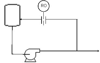
Fig. 1 restriction orifice on pump discharge recycle line
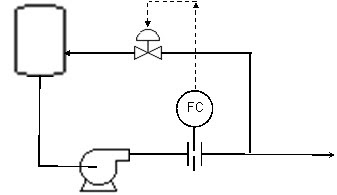
Fig. 2 Flow meter on pump discharge with control valve on recycle line
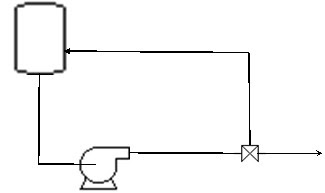
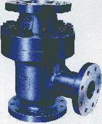
Fig. 3 Automatic Recirculation Valves (ARC) valve
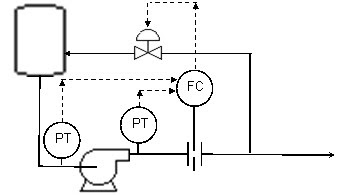
Fig. 4 Flow-Delta P and flow meter on pump discharge with control valve on recycle

The following list out the advantages and disadvantages for above four options
Restriction orifices
- Simple installation
- Maintenance free
- Large pump
- Waste energy all time
- Limit maximum pump output.
Orifice plate in the discharge line
- No continuous recycle thus energy saving
- consumes energy and also slightly reduces pump capacity.
- Using orifice plate to measure flow will results high inaccuracy e.g. minimum flow is 40% of maximum flow, 7% of the set point may be expected.
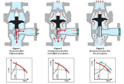
ARC valve
- Simple & effective
- Lack of flexibility.
- Unstable operation
- expensive
Sketches below show outlook and operation of an ARC valve
- Similar to orifice plate option
- Good option for load sharing of pumps in parallel installation
Restriction orifice option is the most common option adopted in many applications with LOW capacity system and a process engineer is advisable to consider this option. However, for HIGH system and appreciable energy losses is possible, a process engineer is advised to consider flow orifice with control valve option. ARC valve may be a good option to consider if process engineer is well aware of the fluid characteristics and familiar with the operation & dynamic of ARC valve. For very high capacity system and load sharing may be expected, process engineer may consider Flow-Delta P option.
Related Topic
- Quick Check Pump Performance Using Motor Data and Field Measure Current
- Is PumpSmart Right Solution for You ?
- Special Flowmeter & Piping Release...
- Vortex Breaker to Avoid Vapor Entrainment
- Estimate Minimum Submergence to Avoid Vapor Entrainment
- Estimate Pump Power Consumption without Vendor Information
- Trim Centrifugal Pump Impeller for Reduced Head
- Quick Check if Pump Performance Curve (Water) is Good for High Viscosity Fluid
Labels: Minimum flow, Pump
Wednesday, August 20, 2008
Display problem ? Click HERE
As the price of electricity, natural gas and other fossil fuels continues to climb, chemical processors are more closely examining high-temperature operations and heat-transfer systems to see if more efficiency can be had. In many cases
it can, and, as a result, heat-transfer projects are not only justifiable, but downright attractive.
There was a dialog among a few heat exchanger specialist from Alfa Laval, Paul Muller, Exergy LLC, etc. The dialog mainly discussed on strategy to improve heat transfer efficiency, heat recovery and efficient process control during this high energy price arena.
A few tips have been present :
- The energy crisis results high prices all of the time shorten paybacks. Energy efficient is one of the way to minimize cost
- Energy efficient heat transfer equipment such as Plate Heat exchanger, Gasketed Heat exchanger, Bonded Heat exchanger, etc is one of the option.
- For a service using Shell & Tube (S&T), the overall heat transfer coefficient (HTC) is around 300 Btu/h ft2°F. However, the overall heat transfer coefficient (HTC) for a compact heat exchanger can be improved 3-4 times (~1000 to 12000 Btu/h ft2°F).
- With lower overall heat transfer coefficient, this may translate into less space, smaller installation and handling cost. Capital cost may not be low as the fabrication cost for compact heat exchanger is high.
- Gasketed Heat exchanger good for maintenance. However shall take additional attention on the compatibility between gasket and fluid.
- All welded or Bonded heat exchanger may be considered if there is gasket & fluid compatible problem
- For laminar flow, heat transfer rate is only the function of fluid thermal conductivity. Operate heat transfer equipment at lamina flow during turndown could significantly reduce it heat transfer rate
- Compact heat exchanger promote turbulence. High turbulence increase heat transfer rate and reduce fouling (read more)
- Thus plant releasing hot exhaust gas from burner, boiler, gas turbine, etc to atmosphere may take the opportunity to recover heat
- Improve temperature control in process system would reduce energy usage
Not a CE subscriber... click here to subscribe FREE Chemical Engineering (CE)
Related Topic
- Practical Design Tips for Heat Exchanger Design
- COMPACT Heat Exchanger Increased Performance, Optimised area utilization, reduce CAPEX & OPEX
- Unexpected high cost of heat exchanger fouling...
- CFD in Compact Heat Exchanger
- Heat Transfer - Internal and External Flow
- Why Lower Fouling in Plate Heat Exchanger ?
Labels: Compact heat Exchanger, Heat Exchanger, Heat Recovery, Heat Transfer, Plate Heat Exchanger
Tuesday, August 19, 2008
Display problem ? Click HERE

For those IEM member who are interested in IEEE Communications Magazine, you may obtains special rates for subscription. $47 for 12 issues for IEM member as compare to normal price of $445 (source).
IEEE Communications Magazine, considered by many to be their most important member benefit, provides timely information on all aspects of communications: monthly feature articles describe technology, systems, services, market trends, development methods, regulatory and policy issues, and significant global events.
 These articles are complemented by a variety of departments, including: Conference Calendar, Book Reviews, the Global Communications Newsletter, Scanning the Literature, New products and Product Spotlights, Society News, Your Internet Connection, News from JSAC, and the CommuniCrostic puzzle. This monthly magazine may become your single most important source of communications information...
Download Form : Click Here
Having problem in browsing Chemical & Process Technology ? Try Firefox. If you are interested in FIREFOX (it is FREE), you may install by clicking below link (or in FREE stuff conner)
Browse the web faster. Get Firefox with Google Toolbar
Related Post
These articles are complemented by a variety of departments, including: Conference Calendar, Book Reviews, the Global Communications Newsletter, Scanning the Literature, New products and Product Spotlights, Society News, Your Internet Connection, News from JSAC, and the CommuniCrostic puzzle. This monthly magazine may become your single most important source of communications information...Download Form : Click Here
Having problem in browsing Chemical & Process Technology ? Try Firefox. If you are interested in FIREFOX (it is FREE), you may install by clicking below link (or in FREE stuff conner)
Browse the web faster. Get Firefox with Google Toolbar
Related Post
- Hydrocarbon Engineering (HE) Subscription Running Fast...
- New Campaign for FREE Subscription to Hydrocarbon Engineering...
- Chemical Engineering Digital Issue for August 2008
- 3 Most Important & FREE Magazines That I Read...
- Don't miss CHEMICAL ENGINEERING Supplementary Issue in Chinese...
- Non - Technical Quick References for a Chemical & Process Engineers
Labels: E-Doc, Education, Learning
Display problem ? Click HERE
Recommended :
- Tips on Succession in FREE Subscription
- Subscribe FREE - Hydrocarbon Engineering
After the earlier announcement of "New Campaign for FREE Subscription to Hydrocarbon Engineering...", the subscription rate increases immediately. The Successor in HE Free subscription has overtook the number of successors in June 2008 (no Free subscription during July 2008), 2 days after the earlier announcement. Thanks and congratulates to those successors.One very good news is the Succession Rate (SR) for HE is 84%.
For those who has not tried, please subscribes quickly before the campaign end or fully subscribed. You may click this link...Subscribe FREE - Hydrocarbon Engineering.
- View Hydrocarbon Engineering (HE) SAMPLE...click here
- Tips on Succession in FREE Subscription...click here
- Subscribe FREE Hydrocarbon Engineering (HE)...click here
Related Post
- New Campaign for FREE Subscription to Hydrocarbon Engineering...
- Chemical Engineering Digital Issue for August 2008
- 3 Most Important & FREE Magazines That I Read...
- Don't miss CHEMICAL ENGINEERING Supplementary Issue in Chinese...
- Non - Technical Quick References for a Chemical & Process Engineers
- Series of Talks for June...
- R&D engineer, Academician and Student...Don't miss this !
Labels: E-Doc, Education, Learning
Monday, August 18, 2008
Display problem ? Click HERE
Recommended :
- Tips on Succession in FREE Subscription
- Subscribe FREE - Hydrocarbon Engineering
A pressure relief valve (PSV) is commonly discharge into a disposal collection system i.e flare, vent, etc. Discharge of a PSV is common smaller than the tail pipe, thus it is always swagged up to tail pipe diameter with an expander. An isolation valve is installed on the discharge of PSV so that the PSV can be isolated for testing and maintenance purpose.

A few questions raised.
i) Should the isolation valve be located between PSV and expander or downstream of expander ?
ii) The momentum (rho V2) is excessive higher than the allowable momentum criteria. Is it acceptable ?
To answer above question, first thing is to analyze the potential issue and problem associate with arrangement :
- High momentum and velocity on the tail pipe - Potentially lead to high vibration and noise level.
- Partial / Full blockage due to installation of devices i.e check valve, flame arrester, butterfly valve (read more in "Should we install Butterfly valve for Pressure Relief Valve (PSV) isolation ?"), etc - Potential lead to reduced flow, increase back pressure and causing PSV chattering. Also posses overpressure thread
- Isolation valve accidentally close by operator - potentially lead to overpressure of protected system
- Isolation valve is "self close" during blowdown due to vibration. High torque caused by asymmetric pressure distribution in the inner surface of isolation valve lead to self closure- potentially lead to overpressure of protected system
- Low pocket cause liquid accumulation - Potential severe corrosion and water hammer in the event of PSV relief
- Two phase relief - Potential of high vibration and surge
- High flow lead to severe acoustically induced vibration (AIV) may potentially lead to mechanical failure of tail pipe and valve.
- Continuous or frequent operation device i.e.manual blowdown valve, control valve discharge flow into flare system, etc may lead to high Likelihood-of-Failure (LOF)
There are a few recommendations that may be considered :
- Momentum & Velocity - Some designer may consider sonic velocity at tail pipe as discussed in "Is PSV tail pipe & lateral at CHOKED (Mach no = 1) Accpetable ?", it is always recommended to design the tail pipe below sonic velocity i.e. 70% of Mach number by increasing tail pipe line size
- Consider to install multiple PSVs i.e 2 x 50% or 3 x 33% to avoid high flow through single PSV. One shall remember, increase number of PSVs would increase number of isolation valves and probability of valve "self-close"
- Consider to install PSV with larger outlet flange to avoid high velocity of the tail pipe (before expander). Detail may refer to API Std 526
- Do not install device with potential of internal failure i.e. check valve, flame arrester, etc.
- Car Seal Open (CSO) or Locked Open (LO) of all manual isolation valve, unless required by safety analysis i.e HAZOP
- Remove handle to minimize the opportunity of operation of isolation valve and reduce potential of self closure of valve, unless required by safety analysis i.e. HAZOP
- If ball valve is installed, Full Bore (FB) ball valve to be used.
- When valve is locked by a locking plate, consider to install heavy duty locking plate to minimize potential of self-closure
- Consider to install valve with "high torque for closure" to minimize potential of self-closure
- Ensure valve (ball type) handle if facing upward to minimize potential of self-closure
- Consider to use gate valve to minimize potential of self-closure, if it is inline with plant wide isolation philosophy
- If gate valve is used, ensure the valve stem and handle is at least 45deg incline downward to avoid blockage due failure of valve internal
- Relocate isolation valve away from PSV i.e. relocated valve to downstream of reducer may reduce the risk of self closure due high vibration but it significantly increases the installation cost. Detail discussion and agreement may take place for a general approach.
- Ensure tail pipe is self drained to collection header. No pocket shall be allowed. Liquid accumulation in low pocket would result serious water hammer in the header in the event of PSV relief.
- If two phase gas-liquid is expected during relieve, ensure the tail pipe is designed for two phase relief i.e. avoid slug flow regime, enhance support, strengthen support, minimize bends, etc
- Acoustically Induced Vibration (AIV) study to be conducted to ensure the tail pipe, subheader and header is mechanically resist the severe AIV.
- If continuous or frequent operation device i.e.manual blowdown valve, control valve discharge flow into flare system, etc are installed on the system which posses high risk on Likelihood-of-Failure (LOF), may consider to conduct Flow-Induced Vibration (FIV) to ensure the tail pipe, subheader and header is mechanically resist the continuous FIV
Recommended Responsei) Should the isolation valve be located between PSV and expander or downstream of expander ?
As discussed above, relocate isolation valve away from PSV i.e. relocated valve to downstream of reducer may reduce the risk of self closure due high vibration but it significantly increases the installation cost. There are still many installation with valve just downstream of PSV has not results the self closure of valves. Thus, installation of isolation valve just downstream of PSV may be acceptable. Detail discussion and agreement may take place for a general approach.
ii) The momentum (rho V2) is excessive higher than the allowable momentum criteria. Is it acceptable ?
This is something that can not be avoided. Several check points shall be implemented.
- Ensure the tail pipe (small section) is not expose to sonic flow risk. Sonic flow would limit flow passage and reduce relief load and potentially lead to overpressure of protected system
- Minimize the tail pipe before expander i.e. fitting-to-fitting installation
- Consider series of recommendation as discussed above
Concluding Remark
Although the installation of downstream of PSV is rather simple, there are still many issue related to proper checks and installation to ensure a well design overpressure protection system.
Above is discussion on PSV discharge to closed collection system, what about discharge to ATM ? Read more in "Concerns & Measures on PSV Discharge to ATM" and "More Concerns Associated to PSV Discharge to ATM".
Related Posts
- More Concerns Associated to PSV Discharge to ATM
- Concerns & Measures on PSV Discharge to ATM
- PSV Chaterring is Destructive...The ways to Prevent...
- Concerns & Recommendations on PSV INLET line
- Is PSV tail pipe & lateral at CHOKED (Mach no = 1) Accpetable ?Should we install Butterfly valve for Pressure Relief Valve (PSV) isolation ?
- Back Pressure Affect Conventional PSV Set Pressure : Case Study #2 - Non-Bonnect Vent
- Back Pressure Affect Conventional PSV Set Pressure : Case Study #1 - Bonnect Vent to ATM
- How Back Pressure Affect Conventional PSV Set Pressure Subject to It Vent
- Several Impacts of Backpressure on Conventional PRV
- Use of conventional type PSV with back pressure exceeded 10% set pressure
- Relate PSV Relieving Flow to Stamped Capacity
- Thermal Relief of Non-Flashing Liquid in Pipe
- Simple Flow Chart to Determine Requirement of Thermal Relief
Labels: Overpressure Protection, Pressure Relief Device
Sunday, August 17, 2008
Display problem ? Click HERE
Recommended :
- Tips on Succession in FREE Subscription
- Subscribe FREE - Hydrocarbon Engineering
Two months ago when we first launched partnership with Netline, Hydrocarbon Engineering (HE) has been fully subscribed within a week. Many of you may have missed this opportunity.A new campaign for FREE subscription to Hydrocarbon Engineering (HE) for qualify professional launched recently, after about 2 months from earlier limited offer. If you missed earlier, please take the opportunity now. Click here to subscribe to Hydrocarbon Engineering (HE)...Below are some brief intro to the contents that you may expect from recent August 2008 release.
"As the 2008 Olympics begin Nancy Yamaguchi’s regional report focuses on China’s energy market and the impact it is having on Asia and the wider world. Ethylene technology is focused on in August with articles from KBR, Callidus and the first part of Shell Global Solution’s article ‘Improving energy utilisation: Part 1’. Also, this issue has a close look at recent compressor technology developments."
Detail contents as follow :- The Evolutionary Chain...explores the evolution of compressor technology...(compressor)
- Strict Environmental Requirements...reports on the change from centrifugal and reciprocating to screw compressors in oil refinery services...(compressor)
- Make The Most of Opportunities...explore centrifugal compressor rerates...(compressor)
- Continuous Optimisation of FCC Catalyst...presents a dynamic approach for today's changing feedstock and product slate requirements...(Refining)
- The Growing Gela Refinery...gives an overview of the Gela refinery's continuing upgrade...(Refining)
- Next Generation SRU Control...examine the implementation of a new burner control with ABB's acid gas analyser at Suncor Simonette Gas Plant...(Gas Treatment)
- The Future of Forming...describes the reinvention of the granulator...(Future)
- Inhibiting High Temperature Sulfidic Corrosion In A Refinery...discuss the inhibition of high temperature sulfidic corrosion in lab evaluations and refinery applications...(Corrosion)
- Supportive Partnerships...explain how to make support strategies truly strategic...(Management)
- Combination Is The Key...examines the advantages of detecting metal loss and pipeline wall thinning with a combination of ultrasonic testing and magnetic flux leakage...(Corrosion)
- There Is Modelling In The Air...discusses the use of computational fluid dynamics (CFD) in air cooled heat exchanger (ACHE) design...(Heat Exchanger)
- Tips on Succession in FREE Subscription...click here
- Subscribe FREE Hydrocarbon Engineering (HE)...click here
Related Post
- Chemical Engineering Digital Issue for August 2008
- 3 Most Important & FREE Magazines That I Read...
- Don't miss CHEMICAL ENGINEERING Supplementary Issue in Chinese...
- Non - Technical Quick References for a Chemical & Process Engineers
- Series of Talks for June...
- R&D engineer, Academician and Student...Don't miss this !
Labels: E-Doc, Education, Learning
Friday, August 15, 2008
Display problem ? Click HERE
Recommended :
- Tips on Succession in FREE Subscription
- Subscribe FREE - Hydrocarbon Engineering
Dynamic simulation is a tools to assist you in design, optimize and operate your plant. It helps to understanding the behavior of your plant and healthier of a control system in achieving the design control. Many of you may have heard about the capability of Dynamic simulation in ASPEN HYSYS. Some of you may have tried to make use this capability. For those who has NO experience at all or those would like to refresh their mind in dynamic simulation using ASPEN HYSYS, the following tutorial is a pretty good tutorial for learning and refreshing.
- Tips on Succession in FREE Subscription
- Subscribe FREE - Hydrocarbon Engineering
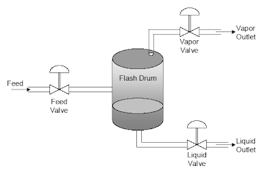
Dynamic simulation is a tools to assist you in design, optimize and operate your plant. It helps to understanding the behavior of your plant and healthier of a control system in achieving the design control. Many of you may have heard about the capability of Dynamic simulation in ASPEN HYSYS. Some of you may have tried to make use this capability. For those who has NO experience at all or those would like to refresh their mind in dynamic simulation using ASPEN HYSYS, the following tutorial is a pretty good tutorial for learning and refreshing.Control System Development with HYSYS
This is a tutorial on the development of dynamic simulations using ASPEN HYSYS which based on implementing three conventional PID control loops on a single-stage flash drum unit for a multicomponent, non-ideal feed stream.
The steps in the development process includes :
- steady-state design and simulation
- specifying dynamic characteristics of process equipment
- switching the simulation over to dynamics mode
- adding feedback controllers to the simulation
- adding strip-chart displays
- carrying out dynamic tests and fitting transfer functions
- tuning the controllers
There is a Dynamic Simulation manual available in ASPEN HYSYS. You may obtain yours copy. Read more in "Useful Documentation for HYSYS ...".
Related Topic
- Running Multiple Thermodynamic Model Simultaneously in HYSYS
- Open HYSYS File in Older Version of HYSYS
- Transfer ALL Streams or Unit Operations Properties From Hysys File to Another Hysys File
- Transfer SINGLE Stream or Unit Operation Properties From Hysys File to Another Hysys File
- Determine Latent Heat for Multi-Component and Relieving Area Using Rigorous Method in HYSYS
- Properly Simulate a Separator with Demister in HYSYS
- Useful Documentation for HYSYS ...
Labels: HYSYS, Process simulation
