Sunday, July 26, 2009
Display problem ? Click HERE
Recommended :Flare is commonly installed in oil and gas process plant to burn hydrocarbon and/or toxic gas to avoid formation of combustible mixture, to minimize green house effect (GHE), to minimize health hazards to personnel on site, etc. Flaring hydrocarbon gas may generate carbon dioxide & water for complete combustion and soot (contribute to smokeless level) & unburnt components (contributes to toxic environment) for incomplete combustion. Besides, heat and noise are generated and radiated and transmitted around the flare tip.
Heat radiated from flare may transmitted in sphere form around the flare tip. Along the transmission, the energy is distributed in sphere form and this lead to reduction in heat radiation level (heat flux, kW/m2). Personnel or equipment along the transmission path will expose to this heat radiation. Personnel or equipment closer to flare tip will experience higher heat radiation level.
With studies conducted by Stoll and Greene (1958), following graph relate heat radiation versus time for Pain threshold and Blister threshold. With heat radiation of 6.3 kW/m2 (2 000 Btu/h·ft2), the pain threshold is reached in 8 s and blistering occurs in 20 s.

The following equation derived from above graph and can be used to relates heat radiation with time for pain and blister thresholds.
Pain threshold :
Blister threshold :
where :
q = heat radiation (kW/m2)
t = time (seconds)
Ref :
(i) A. M. STOLL and L. C. GREEN, The Production of Burns by Thermal Radiation of Medium Intensity, Paper Number 58-A-219, American Society of Mechanical Engineers, New York, 1958
Related Topic
Heat radiated from flare may transmitted in sphere form around the flare tip. Along the transmission, the energy is distributed in sphere form and this lead to reduction in heat radiation level (heat flux, kW/m2). Personnel or equipment along the transmission path will expose to this heat radiation. Personnel or equipment closer to flare tip will experience higher heat radiation level.
With studies conducted by Stoll and Greene (1958), following graph relate heat radiation versus time for Pain threshold and Blister threshold. With heat radiation of 6.3 kW/m2 (2 000 Btu/h·ft2), the pain threshold is reached in 8 s and blistering occurs in 20 s.
The following equation derived from above graph and can be used to relates heat radiation with time for pain and blister thresholds.
Pain threshold :
q = 25.544 x t -0.6742
Blister threshold :
q = 75.691 x t -0.8399
where :
q = heat radiation (kW/m2)
t = time (seconds)
Ref :
(i) A. M. STOLL and L. C. GREEN, The Production of Burns by Thermal Radiation of Medium Intensity, Paper Number 58-A-219, American Society of Mechanical Engineers, New York, 1958
Related Topic
- Simplified Equation for Wind Speed Estimation At Different Height
- Estimate Wind Speed At Flare Tip At Different Height
- Assess AIV with "D/t-method" with Polynomial PWL Limit Line
- Model Fix Pressure Device in FLARENET
- Several Criteria and Constraints for Flare Network - Process
- Several Criteria and Constraints for Flare Network - Piping
- Provide More than One Flare KOD in SERIES
Labels: Environment, Flare, Noise
Saturday, July 25, 2009
Display problem ? Click HERE
Recommended :
Subscribe FREE - Chemical Processing

An explosion caused by pneumatic test failure has occurred in Shanghai LNG Terminal on Feb 06 2009. This accident has resulted one worker killed and fifteen others injured.
Again it was heard that another pneumatic test failure has occurred in Mississippi in July 2009 and lead to at least one fatality and three others injured during a pneumatic test failure. The following photos show how severe is the destruction of pneumatic test failure.

Overall scene

Air-lifted pipeline

Twisted metal pipe
Subscribe FREE - Chemical Processing
An explosion caused by pneumatic test failure has occurred in Shanghai LNG Terminal on Feb 06 2009. This accident has resulted one worker killed and fifteen others injured.
Again it was heard that another pneumatic test failure has occurred in Mississippi in July 2009 and lead to at least one fatality and three others injured during a pneumatic test failure. The following photos show how severe is the destruction of pneumatic test failure.
Overall scene
Air-lifted pipeline
Twisted metal pipe
For those who intended to conduct pneumatic test, really have to ensure that proper procedure is followed. Ensure personnel who are not directly involved in the testing process are removed from the area and not allowed in the area for any reason. If you not involved directly in pneumatic test, please be alert and move away from the testing location.
Following are collection of article that helps you to educate yourself or your operators related to Pneumatic test :
Pneumatic Test During Pre-commissioning
This article has brief introduction about pneumatic test related procedure, safety concern, test pressure level, etc
Pneumatic Test Accident in Singapore
On May 22, 2002, a fatal accident occurred in Singapore involving the failure of a refrigerant receiver during a pneumatic test. In light of this incident, it is appropriate to again remind our readers of the hazards involved in pneumatic tests and to review the precautions that must be taken in conducting such tests.
Hazards of Trapped Pressure and Vacuum
A leak test on a heat exchanger was being conducted using low pressure gas when the tube bundle was ejected with great force striking two employees. One of them died on massive internal injuries...
Pipeline fails under air pressure test - Kills worker
Two workers had completed laying a 30 metre length of 300 mm diameter PVC pipe, in order to connect it to an existing steel pipe, along a suburban roadside. The pipe was then to be pneumatically tested up to a pressure of 690 kPa (100 psi)...
Pneumatic Test Operation Maintenance
This tank is intended for use vented to atmosphere. For outdoor applications, install a weatherproof vent hood or cap on the vent riser pipe and on the interstitial space vent of double wall tanks.
Pneumatic Test - Incident in Brazil
Incident happened in a non-ExxonMobil facility in Brazil during a pneumatic test of the tank associated piping. A blind was NOT installed to isolate the ...
Pneumatic Test - IncidentASTM A1047 / A1047M - 05
ASTM A1047 / A1047M - 05 Standard Test Method for Pneumatic Leak Testing of Tubing
Read others incident...Click HERE
Related Post
- Communication Breakdown...Key to Failure...
- "Fire from Ice" - Lesson Learned & Key Recommendations
- Compressed Gas Incident - Awareness & Learning Fundamentals...
- Pipeline rupture In Varanus Island
- Break the Rules... Pay the Price...
- Vacuum Hazard - Another Catastrophic Factor...
- Extra Caution When Eliminating Overpressure by Fire Attacks
Sunday, July 19, 2009
Display problem ? Click HERE

FREE Chemical Engineering Digital Issue for July 2009 has been released !
Chemical Engineering has just released FREE July 2009 issue. If you are subscriber of Chemical Engineering, you should have received similar notification.
***********************
Interesting articles for this month :
FAYF - Flowmeter Selection
This one-page guide details important facts for selecting a flowmeter
Revamps - Strategies for A Smooth Turnaround
Tie-in opportunities are few and far between. These rules of thumb will help make sure everything and everyone line up in time
Removal of Fouling Deposits on Heat Transfer Surfaces in Coal-Fired Process Heaters and Boilers
When conventional soot blowers are inadequate, an automated shot-blasting system offers a powerful solution
* If you encounter problem in reading this article, you may check this article via this link (for FREE subscriber only).
Disperse Difficult Solids
Recent advances in mixing technology offer increased efficiency in dispersing powdered additives into liquids for both low- and high-viscosity applications
***********************
TIPS
If you are subscriber, you may access previous digital releases. Learn more in "How to Access Previous Chemical Engineering Digital Issue".
If you yet to be subscriber of Chemical Engineering, requested your FREE subscription via this link (click HERE). Prior to fill-up the form, read "Tips on Succession in FREE Subscription".
Related Post
- How to Access Previous Chemical Engineering Digital Issue
- Tips on Succession in FREE Subscription
- 3 Most Important & FREE Magazines That I Read...
- Non - Technical Quick References for a Chemical & Process Engineers
- More You Share More You Learn
- Knowledge is Own by Everyone but Not Someone
Labels: E-Doc, Education, Learning
Saturday, July 18, 2009
Display problem ? Click HERE
Recommended :
- Tips on Succession in FREE Subscription
- Subscribes to FREE Hydrocarbon Processing
 High frequency acoustic Excitation downstream of pressure reducing device and potential of downstream piping failure on Acoustic Induced Vibration (AIV) has raised concern in many process plant
Earlier post "Extra Attention to Common Point and Similarity on AIV Failure" has discussed the common points and similarity of AIV such as typical failure location, system experienced failure in the past, failure time & period and Mach no. An engineer assessing AIV shall pay extra attention in these factors.
There are several methods have been discussed earlier in assessing AIV problem. There are "D-method" and "D/t-method". These two methods are widely used by many engineering contractor and consultants in many previous projects. There is another method, the Energy Input method or "E-method" which has been introduced in mid 1990.
Energy Input or E-method In Assessing AIV
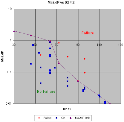
The "E-method" is focus on the acoustic energy transmitted along the pipe, downstream of pressure reducing devices. The acoustic energy can be measured by Ma2.dP where Ma2 is the Mach number at downstream pipe and dP is the pressure drop across pressure reducing devices. The higher the acoustic energy or Ma2.dP, higher the risk for AIV failure.
Similar to the other two methods, based on data available in Carucci & Mueller (1982) studies, "No failure" and "Failure" points have been plotted in following chart with Ma2.dP versus Pipe Diameter / Wall thickness (D/t).
Note :
1) A "failure" point (54.8, 0.35) is below curve. It is failed on bad welding. No further failure after good welding.
2) Red point are "failure" point and Blue point are "No failure" point
From above chart a clear distinctive limit line can be established. This line may be used to assess potential failure of piping downstream of pressure reducing device. Any point above the line potentially fail on AIV, piping treatment or redesign required to minimise the risk of AIV failure.
*As limit line is straight or following any pattern, a representative equation is yet to be developed.
Related Topic
- Tips on Succession in FREE Subscription
- Subscribes to FREE Hydrocarbon Processing
High frequency acoustic Excitation downstream of pressure reducing device and potential of downstream piping failure on Acoustic Induced Vibration (AIV) has raised concern in many process plantEarlier post "Extra Attention to Common Point and Similarity on AIV Failure" has discussed the common points and similarity of AIV such as typical failure location, system experienced failure in the past, failure time & period and Mach no. An engineer assessing AIV shall pay extra attention in these factors.
There are several methods have been discussed earlier in assessing AIV problem. There are "D-method" and "D/t-method". These two methods are widely used by many engineering contractor and consultants in many previous projects. There is another method, the Energy Input method or "E-method" which has been introduced in mid 1990.
Energy Input or E-method In Assessing AIV
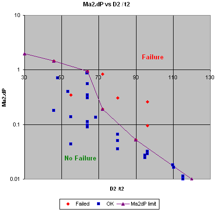
The "E-method" is focus on the acoustic energy transmitted along the pipe, downstream of pressure reducing devices. The acoustic energy can be measured by Ma2.dP where Ma2 is the Mach number at downstream pipe and dP is the pressure drop across pressure reducing devices. The higher the acoustic energy or Ma2.dP, higher the risk for AIV failure.
Similar to the other two methods, based on data available in Carucci & Mueller (1982) studies, "No failure" and "Failure" points have been plotted in following chart with Ma2.dP versus Pipe Diameter / Wall thickness (D/t).
Note :
1) A "failure" point (54.8, 0.35) is below curve. It is failed on bad welding. No further failure after good welding.
2) Red point are "failure" point and Blue point are "No failure" point
From above chart a clear distinctive limit line can be established. This line may be used to assess potential failure of piping downstream of pressure reducing device. Any point above the line potentially fail on AIV, piping treatment or redesign required to minimise the risk of AIV failure.
*As limit line is straight or following any pattern, a representative equation is yet to be developed.
Related Topic
- Assess AIV with "D/t-method" with Polynomial PWL Limit Line
- Assess AIV with "D/t-method" with Logarithm PWL Limit Line
- Extra Attention to Common Point and Similarity on AIV Failure
- Piping Excitation When Expose to Acoustic Energy
- Acoustic Induced Vibration (AIV) Fatigue
- Sound Power Level (PWL) Prediction from AIV Aspect
- Several Criteria and Constraints for Flare Network - Piping
