Saturday, May 30, 2009
Display problem ? Click HERE

A pressure vessel or system expose to external fire, entire system may be isolated automatically by a plant wide emergency shutdown system (ESD) and emergency depressuring system will be initiated to depressure system to safe level and evacuate the inventory from high risk area (expose to external fire) to disposal system. Depressuring system is known as one of the most effective measures against external fire risk. Besides, there are others measures as discussed in "Protective Measures against FIRE...".
Pressure relief device (PRD) may not protect pressure vessel or system from external fire. Having said that PRD may serve in some circumtances to "buy time" for operator action. Besides, design code and/or local regulation demand a PRD in pressure vessel or system as ultimate protection.
One may have process simulation for normal production system. The stream for vessel or system expose to fire is at normal operating pressure and temperature. How shall one can adjust the process simulation to bring it up the relieving pressure ? One may consider a constant density method.
Constant density method
Pressure vessel expose to fire will be isolated and settled-out. Read more in "Adjusted Method For Compressor Settle Out (with Vapor & Liquid) Using HYSYS". Assuming no credit for automatic depressuring system and operator intervention, the inventory trapped in the pressure vessel will remain as trapped vapor mass (MV0) with vapor volume (VV0) and liquid mass (ML0) with liquid volume (VL0) at normal pressure (P0) and temperature (T0) when ESD is just initiated. Total trapped mass (MT0) will be MV0 + ML0 and total trapped volume (VT0) will be VV0 + VL0. Mix denstiy will be MT0/VT0.
Trapped inventory will be heated up with external fire. Heat added into the trapped system will cause temperature rise, more liquid vaporise and pressure rise upto relieving pressure, before pressure relief device is popped open. At relieving condition (relieving pressure and temperature), trapped vapor mass (MVr) with vapor volume (VVr) and liquid mass (MLr) with liquid volume (VLr). Total trapped mass (MTr) will be MVr + MLr and total trapped volume (VTr) will be VVr + VLr. Mix denstiy will be MTr/VTr. As there is no inventory evacuated from the system, total trapped mass (MT0) and volume (VT0) at normal condition will be same as trapped mass (MTr) and volume (VTr) at relieving condition.
MT0 = MTr
VT0 = VTr
VT0 = VTr
Similar mix density (MT0/VT0) will remain same.
MT0/VT0 = MTr/VTr
This is commonly known as constant density method.
Related Topic
- Don't misunderstood depressuring
- Depressuring Flow - Quick Manual Method
- Protective Measures against FIRE other than Pressure Relief Device (PRD)
- Adjusted Method For Compressor Settle Out (with Vapor & Liquid) Using HYSYS
- Simple Manual Method for Settle Out Condition Estimation
- Simple Method For Compressor Settle Out Using HYSYS
- Depressuring - Save Some Time in HYSYS - FLARENET Iteration
Labels: Fire, Overpressure Protection, Pressure Relief Device
Tuesday, May 26, 2009
Display problem ? Click HERE
Recommended :
- Tips on Succession in FREE Subscription
- Subscribes to FREE Hydrocarbon Processing
 Pressure reducing device such as control valve, pressure relief valve, restriction orifice, etc, there will be pressure drop and mass passing through these device, internal acoustic energy is generated and transmitted to downstream piping and potentially lead to severe piping excitation, vibration and stresses on downstream piping and potentially lead to fatigue failure. Internal acoustic energy transmitted along the pipe may also transmitted to through the pipe and emitted as Noise.
One of the common safety requirement is limit the noise level to 85 dBA (Noise level with A-weighted) in continuous exposure and 115 dBA during intermittent exposure. In earlier conceptual or Front End Engineering Design (FEED) stage, the noise level across pressure reducing device may be estimated to determine overall noise control philosophy. The following will present a simple method to estimate noise level generated at 1 meter from a pressure reducing device.
Noise Level Estimation
Noise level at 1 meter from a pressure reducing device can be estimated from Sound Power Level (PWL) as discussed in "Sound Power Level (PWL) Prediction from AIV Aspect". The Sound Power Level will be transmitted across the pipe wall and emitted to atmosphere. There will be noise correction when Sound power is transmitted across pipe wall (metal). The noise correction is subject to wall thickness. Thicker wall will result higher noise correction. Following are typical noise correction for pipe size and wall thickness.
Noise level at 1 meter from a pressure reducing device,
- Tips on Succession in FREE Subscription
- Subscribes to FREE Hydrocarbon Processing
Pressure reducing device such as control valve, pressure relief valve, restriction orifice, etc, there will be pressure drop and mass passing through these device, internal acoustic energy is generated and transmitted to downstream piping and potentially lead to severe piping excitation, vibration and stresses on downstream piping and potentially lead to fatigue failure. Internal acoustic energy transmitted along the pipe may also transmitted to through the pipe and emitted as Noise.One of the common safety requirement is limit the noise level to 85 dBA (Noise level with A-weighted) in continuous exposure and 115 dBA during intermittent exposure. In earlier conceptual or Front End Engineering Design (FEED) stage, the noise level across pressure reducing device may be estimated to determine overall noise control philosophy. The following will present a simple method to estimate noise level generated at 1 meter from a pressure reducing device.
Noise Level Estimation
Noise level at 1 meter from a pressure reducing device can be estimated from Sound Power Level (PWL) as discussed in "Sound Power Level (PWL) Prediction from AIV Aspect". The Sound Power Level will be transmitted across the pipe wall and emitted to atmosphere. There will be noise correction when Sound power is transmitted across pipe wall (metal). The noise correction is subject to wall thickness. Thicker wall will result higher noise correction. Following are typical noise correction for pipe size and wall thickness.
| Noise Correction | ||
| Nominal Dia. (Inch) | Wall thickness (mm) | Noise Correction (dB) |
| 25 | 3.38 | 54 |
| 50 | 3.91 | 50 |
| 100 | 6.02 | 50 |
| 150 | 7.12 | 49 |
| 200 | 8.18 | 48 |
| 250 | 9.3 | 47 |
| 300 | 9.53 | 47 |
| 350 | 9.53 | 46 |
| 450 | 9.53 | 46 |
| 600 | 9.53 | 45 |
| 750 | 9.53 | 43 |
| 900 | 9.53 | 43 |
| 1050 | 9.53 | 42 |
Noise level at 1 meter from a pressure reducing device,
L1m = PWL - LA
where
PWL = Sound Power Level (from Sound Power Level (PWL) Prediction)
LA = Noise correction from above table
Example
PWL = 10 x Log [((87-7) / (87+1.01325))^3.6
x (100,000 / 3600)^2
x ((50+273.15)/22)^1.2]
+ 126.1
PWL = 167.5 dB
Noise level at 1m,
L1m = PWL - LA
L1m = 167.5 - 46
L1m = 121.5 dBA
As the noise level at 1m (normal trim) is 121.5 dBA, this is far too big from normal requirement. A low noise trim control valve may be considered and/or acoustic insulation to be provided.
Related Topic
PWL = Sound Power Level (from Sound Power Level (PWL) Prediction)
LA = Noise correction from above table
Example
A pressure control valve (PV) passing 100,000 kg/h of gas with molecular weight (MW) of 22. The inlet condition is 87 barg and 50 degC and downstream pressure is about 7 barg. The pipe diameter is 18 inch with wall thickness of 9.53mm, estimate noise level at 1 m from PV.
PWL = 10 x Log [((87-7) / (87+1.01325))^3.6
x (100,000 / 3600)^2
x ((50+273.15)/22)^1.2]
+ 126.1
PWL = 167.5 dB
Noise level at 1m,
L1m = PWL - LA
L1m = 167.5 - 46
L1m = 121.5 dBA
As the noise level at 1m (normal trim) is 121.5 dBA, this is far too big from normal requirement. A low noise trim control valve may be considered and/or acoustic insulation to be provided.
Related Topic
- Assess AIV with "D/t-method"
- Extra Attention to Common Point and Similarity on AIV Failure
- Piping Excitation When Expose to Acoustic Energy
- Acoustic Induced Vibration (AIV) Fatigue
- Sound Power Level (PWL) Prediction from AIV Aspect
- Several Criteria and Constraints for Flare Network - Piping
- Flow Element (FE) Upstream or Downstream of Control Valve (CV) ?
Labels: Air Pollution Control, AIV, Safety
Thursday, May 21, 2009
Display problem ? Click HERE
This post is intended to provide supplementary information for earlier post "API Std 521 ADDENDUM, MAY 2008 - Check Out Revised Section".
Addendum May 2008
API has released the Addendum details to API Std 521. It describes in detail the modified sections compare to earlier release in 2007. You may download Addendum May 2008 from here.
Errata June 2007
For those who don't not aware the Errata in June 2007 for API Std 521 released in 2007, you may read "ERRATA - API Std 521, Pressure Relieving and Depressuring Systems" and download Errata June 2007 from here.
Related Topic
- API Std 521 ADDENDUM, MAY 2008 - Check Out Revised Section
- ERRATA - API Std 521, Pressure Relieving and Depressuring Systems
- Workbook for Chemical Reactor Relief System Sizing
- A must have book...Emergency Relief System Design Using DIERS Technology
- Requirement of overpressure protection devices on system design to PIPING code
- Discussion on ISENTROPIC and ISENTHALPIC process via Relief Valve
Labels: Depressurization, Loss Prevention, Overpressure Protection, Pressure Relief Device
Tuesday, May 19, 2009
Display problem ? Click HERE
Recommended :
- Tips on Succession in FREE Subscription
- Subscribe FREE - Chemical Processing
 Flare is commonly installed in oil and gas process plant to burn hydrocarbon and/or toxic gas to avoid formation of combustible mixture, to minimize green house effect (GHE), to minimize health hazards to personnel on site, etc. Although there are many benefits in using flare for proper disposal of hydrocarbon gases, combustion efficiency is still a common concern about flare. It is commonly accepted a flare combustion efficiency can reach approximately 98% (refer API Std 521). This would still results some remaining unburnt hydrocarbon gases release into atmosphere. Thus, there are operators especially in high environment concern area, zero emission and flaring principle is implemented.
Flare is normally lit and a highly reliable pilot system is maintaining the flame at the flare tip. In an extreme condition i.e. storm, heavy rain, strong wind, long serviced pilot, etc, flare may lose the flame. This situation commonly called as flame-out condition. Any release during this period would lead to flammable gas (heavier than air) release and settle to ground level in process area. Wind blowing may disperse the flammable gas and reduce concentration of flammable gas at ground level. However, there is still possibility of flammable gas settled and form combustible mixture. Thus, it is very important to estimate maximum concentration of flammable gas at ground level.
Nowadays with sophisticated software development, software such as PHAST may be used to estimate concentration of flammable gas at ground level at specific location. However, quick estimation method may be important during conceptual phase. Following will present a simple estimation method to calculate maximum concentration of flammable gas at ground level.
Maximum Ground Level Concentration of flammable gas,
where
C = Flammable gas concentration (g/m3)
Q = Mass flow of flammable gas (g/s)
U = Wind speed (m/s)
H' = Effective height (m)
Effective flare height can be determined with
where
Hs = Flare stack height (m)
ds = Flare tip diameter (m)
Vex = Exit velocity (m/s)
U = Wind velocity (m/s)
Concentration conversion g/m3 to ppm,
where
[C in ppm] = Concentration in ppm
[C in g/m3] = Concentration in mg/m3
MW = Gas molecular weight
Example
Estimate the maximum ground-level concentration, C, if a flammable gas is accidentally released unburned from a flare, if the release rate to the atmosphere, Q, is 25,200 g/s, the exit
velocity is 83.8 m/s, and flare tip diameter is 0.46 m. The flare stack height is 61 m. Assume that the wind speed 3.1 m/s. The molecular weight of the gas is 54.
H' = Hs + 3 ds Vex / U
H' = 61 + 3 (0.46) (83.8 / 3.1)
H' = 98.3 m
C = 0.23 x Q / (U x H'2)
C = 0.23 x 25200 / (3.1 x 98.32)
C = 0.193 g/m3
[C in ppm] = [C in mg/m3] x 24.45 / MW
[C in ppm] = 0.193 x 1000 x 24.45 / 54
[C in ppm] = 87.6 ppm
Ref : Section 15.11, Handbook of Chemical Engineering Calculations, 3rd Edition, Nicholas P. Chopey
- Tips on Succession in FREE Subscription
- Subscribe FREE - Chemical Processing
Flare is commonly installed in oil and gas process plant to burn hydrocarbon and/or toxic gas to avoid formation of combustible mixture, to minimize green house effect (GHE), to minimize health hazards to personnel on site, etc. Although there are many benefits in using flare for proper disposal of hydrocarbon gases, combustion efficiency is still a common concern about flare. It is commonly accepted a flare combustion efficiency can reach approximately 98% (refer API Std 521). This would still results some remaining unburnt hydrocarbon gases release into atmosphere. Thus, there are operators especially in high environment concern area, zero emission and flaring principle is implemented.Flare is normally lit and a highly reliable pilot system is maintaining the flame at the flare tip. In an extreme condition i.e. storm, heavy rain, strong wind, long serviced pilot, etc, flare may lose the flame. This situation commonly called as flame-out condition. Any release during this period would lead to flammable gas (heavier than air) release and settle to ground level in process area. Wind blowing may disperse the flammable gas and reduce concentration of flammable gas at ground level. However, there is still possibility of flammable gas settled and form combustible mixture. Thus, it is very important to estimate maximum concentration of flammable gas at ground level.
Nowadays with sophisticated software development, software such as PHAST may be used to estimate concentration of flammable gas at ground level at specific location. However, quick estimation method may be important during conceptual phase. Following will present a simple estimation method to calculate maximum concentration of flammable gas at ground level.
Maximum Ground Level Concentration of flammable gas,
C = 0.23 x Q / (U x H'2)
where
C = Flammable gas concentration (g/m3)
Q = Mass flow of flammable gas (g/s)
U = Wind speed (m/s)
H' = Effective height (m)
Effective flare height can be determined with
H' = Hs + 3 ds Vex / U
where
Hs = Flare stack height (m)
ds = Flare tip diameter (m)
Vex = Exit velocity (m/s)
U = Wind velocity (m/s)
Concentration conversion g/m3 to ppm,
[C in ppm] = [C in mg/m3] x 24.45 / MW
where
[C in ppm] = Concentration in ppm
[C in g/m3] = Concentration in mg/m3
MW = Gas molecular weight
Example
Estimate the maximum ground-level concentration, C, if a flammable gas is accidentally released unburned from a flare, if the release rate to the atmosphere, Q, is 25,200 g/s, the exit
velocity is 83.8 m/s, and flare tip diameter is 0.46 m. The flare stack height is 61 m. Assume that the wind speed 3.1 m/s. The molecular weight of the gas is 54.
H' = Hs + 3 ds Vex / U
H' = 61 + 3 (0.46) (83.8 / 3.1)
H' = 98.3 m
C = 0.23 x Q / (U x H'2)
C = 0.23 x 25200 / (3.1 x 98.32)
C = 0.193 g/m3
[C in ppm] = [C in mg/m3] x 24.45 / MW
[C in ppm] = 0.193 x 1000 x 24.45 / 54
[C in ppm] = 87.6 ppm
Ref : Section 15.11, Handbook of Chemical Engineering Calculations, 3rd Edition, Nicholas P. Chopey
***********************************
Above equations have been programmed by Ankur, a experience Chemical Engineer share with readers of Chemical and Process Technology. You may download here.
Thanks to Ankur
Download
*If you have any useful program and articles would like to share within our community, please send to me.
Related Topic
Thanks to Ankur
Download
*If you have any useful program and articles would like to share within our community, please send to me.
Related Topic
- Model Fix Pressure Device in FLARENET
- Quick Estimate Flare Stack Diameter
- Estimate Subsonic Flare Tip Pressure Drop With Graph Derived Correlation
- Quick Estimate Flare Tip Pressure Drop
- Several Criteria and Constraints for Flare Network - Process
- Several Criteria and Constraints for Flare Network - Piping
- Provide More than One Flare KOD in SERIES
Sunday, May 17, 2009
Display problem ? Click HERE
Recommended :
Tips on Succession in FREE Subscription
Subscribes to FREE Hydrocarbon Processing
Earlier post "Tank Normal Venting Rate Estimation Using Siddhartha Equation", Siddhartha equation has been presented. The proposed equations are rather simple and easy to use.
Following post will discuss the comparison between prediction Siddhartha equation and API Std 2000 data. New equations with better accuracy are proposed.
Thermal Inbreathing
From earlier post, thermal inbreathing flow cause by ambient cooling can be determined based on following equations :
If Vtank less than or equal to 3500 m3,
where
Qthermal in,air = Thermal inbreathing in Sm3/h (Air)
Vtank = Tank capacity in m3
To convert Sm3/h to Nm3/h, divide inbreathing / outbreathing flow with a factor of 1.055. Refer "Relate NORMAL to STANDARD Volumetric Flow"
The error difference for thermal inbreathing between above equations and API Std 2000 data is about :
If Vtank more than 3500 m3, a polynomial equation is proposed.
with
a = -4.333E-23
b = + 4.974E-18
c = - 2.281E-13
d = + 5.328E-09
e = - 6.681E-05
f = + 0.494
g = - 549.435
where
Qthermal in,air = Thermal inbreathing in Nm3/h (Air)
Vtank = Tank capacity in m3
Thermal Outbreathing
From earlier post, thermal outbreathing flow cause by ambient heating can be determined based on following equations :
Liquids with a flash point (FP) greater than 37.8°C or Normal Boiling Point (NBP) above 149°C
If Vtank less than or equal to 3500 m3,
If Vtank more than 3500 m3,
where
Qthermal out,air = Thermal inbreathing in Sm3/h (Air)
Vtank = Tank capacity in m3
The error difference for thermal inbreathing between above equations and API Std 2000 data is in the range of 0.09% - 16.88%
Above error diefference is rather big. However, it may be still acceptable in practical application. Care shall be taken when these equqation are used.
Further investigations found the following equations giving better estimation :
a) Liquids with a flash point (FP) greater than 37.8°C or Normal Boiling Point (NBP) above 149°C
If Vtank less than or equal to 3000 m3,
with
a = -2.659E-12
b = + 6.206E-08
c = - 5.35E-03
d = + 2.073
e = - 2541.692
If Vtank more than 8000 m3,
b) Liquids with a flash point less than 37.8°C or Normal Boiling Point (NBP) below 149°C
Similar equation [3] may be used.
Related Post
Tips on Succession in FREE Subscription
Subscribes to FREE Hydrocarbon Processing
Earlier post "Tank Normal Venting Rate Estimation Using Siddhartha Equation", Siddhartha equation has been presented. The proposed equations are rather simple and easy to use.
Following post will discuss the comparison between prediction Siddhartha equation and API Std 2000 data. New equations with better accuracy are proposed.
Thermal Inbreathing
From earlier post, thermal inbreathing flow cause by ambient cooling can be determined based on following equations :
If Vtank less than or equal to 3500 m3,
Qthermal in,air = 0.178 x Vtank......[1]
If Vtank more than 3500 m3,Qthermal in,air = 3.2 x Vtank0.651......[2]
where
Qthermal in,air = Thermal inbreathing in Sm3/h (Air)
Vtank = Tank capacity in m3
To convert Sm3/h to Nm3/h, divide inbreathing / outbreathing flow with a factor of 1.055. Refer "Relate NORMAL to STANDARD Volumetric Flow"
The error difference for thermal inbreathing between above equations and API Std 2000 data is about :
- 0.17% for tank volume less than or equal to 3500 m3
- 3.75% for tank volume more than 3500 m
If Vtank more than 3500 m3, a polynomial equation is proposed.
Qthermal in,air = a.Vtank6 + b.Vtank5+ c.Vtank4
+ d.Vtank3 + e.Vtank2 + f.Vtank + g ......[3]
+ d.Vtank3 + e.Vtank2 + f.Vtank + g ......[3]
with
a = -4.333E-23
b = + 4.974E-18
c = - 2.281E-13
d = + 5.328E-09
e = - 6.681E-05
f = + 0.494
g = - 549.435
where
Qthermal in,air = Thermal inbreathing in Nm3/h (Air)
Vtank = Tank capacity in m3
The error difference for thermal inbreathing between above proposed equation and API Std 2000 data is about 1.25% for tank volume more than 3500 m
Thermal Outbreathing
From earlier post, thermal outbreathing flow cause by ambient heating can be determined based on following equations :
Liquids with a flash point (FP) greater than 37.8°C or Normal Boiling Point (NBP) above 149°C
If Vtank less than or equal to 3500 m3,
Qthermal out,air = 0.107 x Vtank ......[4]
If Vtank more than 3500 m3,
Qthermal out,air = 1.92 x Vtank0.651 ......[5]
where
Qthermal out,air = Thermal inbreathing in Sm3/h (Air)
Vtank = Tank capacity in m3
The error difference for thermal inbreathing between above equations and API Std 2000 data is in the range of 0.09% - 16.88%
Further investigations found the following equations giving better estimation :
a) Liquids with a flash point (FP) greater than 37.8°C or Normal Boiling Point (NBP) above 149°C
If Vtank less than or equal to 3000 m3,
Qthermal out,air = 0.1012 x Vtank ......[6]
If Vtank more than 3000m3 and less than or equal to 8000 m3,Qthermal out,air =+ a.Vtank4 + b.Vtank3
+ c.Vtank2 + d.Vtank + e ......[7]
+ c.Vtank2 + d.Vtank + e ......[7]
with
a = -2.659E-12
b = + 6.206E-08
c = - 5.35E-03
d = + 2.073
e = - 2541.692
If Vtank more than 8000 m3,
Qthermal out,air = a.Vtank5 + b.Vtank4+ c.Vtank3
+ d.Vtank2 + e.Vtank + f ......[8]
The error difference for thermal inbreathing between above equations and API Std 2000 data is in the range of 0.1 - 3.95%.with
a = 1.0318E-18
b = - 8.775E-14
c = + 2.742E-09
d = - 3.925E-05
e = + 0.302
f = - 282.206
a = 1.0318E-18
b = - 8.775E-14
c = + 2.742E-09
d = - 3.925E-05
e = + 0.302
f = - 282.206
b) Liquids with a flash point less than 37.8°C or Normal Boiling Point (NBP) below 149°C
Similar equation [3] may be used.
Related Post
- Tank Normal Venting Rate Estimation Using Siddhartha Equation
- PSV for Shell-and-Tube HEX Tube Side Overpressure Protection against External Fire Attack ?
- Should we consider JET FIRE for Pressure Relief Valve (PSV) load determination ?
- Protective Measures against FIRE other than Pressure Relief Device (PRD)
- Extra Caution When Eliminating Overpressure by Fire Attacks
- Calculate Wetted Surface Area For Horizontal Vessel With Elliptical Head (Simplified)
- Calculate Wetted Surface Area For Horizontal Vessel With Elliptical Head
Labels: Environment, Tank
Wednesday, May 13, 2009
Display problem ? Click HERE

Chemical & Process Technology webblog is in Twitter now !
Twitter is a free service that lets you keep in touch with Chemical & Process Technology webblog through the exchange of quick, frequent answers to one simple question: What is Chemical & Process Technology webblog sharing now ? What JoeWong, key author of Chemical & process Technology and other Chem Jedies are learning now ?
Posting in Twitter is not only for you to obtain update from Chemical & Process Technology, it is also intended to simplify the posting and share with more Chem & Proc Eng...
Look at ChemProcTech in Twiiter here...
Related Post
- Chemical Engineer Average Salary From 2005 - 2009
- 3 Most Important & FREE Magazines That I Read...
- Don't miss CHEMICAL ENGINEERING Supplementary Issue in Chinese...
- Non - Technical Quick References for a Chemical & Process Engineers
- R&D engineer, Academician and Student...Don't miss this !
- More You Share More You Learn
- Knowledge is Own by Everyone but Not Someone
Labels: Education, Learning, NEWS
Monday, May 11, 2009
Display problem ? Click HERE
Recommended :
- Tips on Succession in FREE Subscription
- Subscribe FREE - Processing Magazine

Liquid product like Chemical, condensate, etc is commonly stored in fixed roof vertical cylindrical tank. Inert gas blanketing system is provided to avoid air and moisture contact and contaminate liquid product. Liquid movement by content filling (pump-in) or emptying (pump out) and weather changes (ambient heating or cooling) will results internal pressure increase (overpressure) or decrease (vacuum) in the tank. Thus, a protecting system providing inbreathing or outbreathing gas is provided to maintain a constant pressure in the tank.
Inbreathing
Emptying (pump-out) and ambient cooling will lead to normal inbreathing. Siddhartha (2006) proposed a general equation to determine inbreathing flow :
If Vtank less than or equal to 3500 m3,
If Vtank more than 3500 m3,
where
Qin,air = Total inbreathing in Sm3/h (Air)
Qoutflow = Pump-out or emptying in m3/h
Vtank = Tank capacity in m3
Outbreathing
Filling (pump-out) and ambient heating will lead to normal outbreathing. Siddhartha (2006) proposed a general equation to determine outbreathing flow :
Liquids with a flash point (FP) greater than 37.8°C or Normal Boiling Point (NBP) above 149°C
If Vtank less than or equal to 3500 m3,
If Vtank more than 3500 m3,
Liquids with a flash point less than 37.8°C or Normal Boiling Point (NBP) below 149°C
If Vtank less than or equal to 3500 m3,
If Vtank more than 3500 m3,
where
Qout,air = Total outbreathing in Sm3/h (Air)
Qinflow = Pump-in or filling in m3/h
Vtank = Tank capacity in m3
To convert Sm3/h to Nm3/h, divide inbreathing / outbreathing flow with a factor of 1.055. Refer "Relate NORMAL to STANDARD Volumetric Flow"
Note:
Sm3/h indicates volume flow at standard conditions of 101.325 kPa(a) and 15 degC
Nm3/h indicates volume flow at standard conditions of 101.325 kPa(a) and 0 degC
Ref : "Understanding Atmospheric Storage Tanks" by Siddhartha Mukherjee, Chemical Engineering, April 2006
Above equations have been programmed by Ankur, a experience Chemical Engineer, share with readers of Chemical and Process Technology. You may download here.
Thanks to Ankur
Download
*If you have any useful program and would like to share within our community, please send to me.
Related Post
- Tips on Succession in FREE Subscription
- Subscribe FREE - Processing Magazine
Liquid product like Chemical, condensate, etc is commonly stored in fixed roof vertical cylindrical tank. Inert gas blanketing system is provided to avoid air and moisture contact and contaminate liquid product. Liquid movement by content filling (pump-in) or emptying (pump out) and weather changes (ambient heating or cooling) will results internal pressure increase (overpressure) or decrease (vacuum) in the tank. Thus, a protecting system providing inbreathing or outbreathing gas is provided to maintain a constant pressure in the tank.
Inbreathing
Emptying (pump-out) and ambient cooling will lead to normal inbreathing. Siddhartha (2006) proposed a general equation to determine inbreathing flow :
If Vtank less than or equal to 3500 m3,
Qin,air = Qoutflow + 0.178 x Vtank
If Vtank more than 3500 m3,
Qin,air = Qoutflow + 3.2 x Vtank0.651
where
Qin,air = Total inbreathing in Sm3/h (Air)
Qoutflow = Pump-out or emptying in m3/h
Vtank = Tank capacity in m3
Outbreathing
Filling (pump-out) and ambient heating will lead to normal outbreathing. Siddhartha (2006) proposed a general equation to determine outbreathing flow :
Liquids with a flash point (FP) greater than 37.8°C or Normal Boiling Point (NBP) above 149°C
If Vtank less than or equal to 3500 m3,
Qout,air = 1.069 x Qinflow + 0.107 x Vtank
If Vtank more than 3500 m3,
QOut,air = 1.069 x Qinflow + 1.92 x Vtank0.651
Liquids with a flash point less than 37.8°C or Normal Boiling Point (NBP) below 149°C
If Vtank less than or equal to 3500 m3,
Qout,air = 2.138 x Qinflow + 0.178x Vtank
If Vtank more than 3500 m3,
Qout,air = 2.138 x Qinflow + 3.2 x Vtank0.651
where
Qout,air = Total outbreathing in Sm3/h (Air)
Qinflow = Pump-in or filling in m3/h
Vtank = Tank capacity in m3
To convert Sm3/h to Nm3/h, divide inbreathing / outbreathing flow with a factor of 1.055. Refer "Relate NORMAL to STANDARD Volumetric Flow"
Note:
Sm3/h indicates volume flow at standard conditions of 101.325 kPa(a) and 15 degC
Nm3/h indicates volume flow at standard conditions of 101.325 kPa(a) and 0 degC
Ref : "Understanding Atmospheric Storage Tanks" by Siddhartha Mukherjee, Chemical Engineering, April 2006
**********************************
Above equations have been programmed by Ankur, a experience Chemical Engineer, share with readers of Chemical and Process Technology. You may download here.
Thanks to Ankur
Download
*If you have any useful program and would like to share within our community, please send to me.
Related Post
- Tank Thermal Breathing - Proposed Equation Correlate API Std 2000 Data
- PSV for Shell-and-Tube HEX Tube Side Overpressure Protection against External Fire Attack ?
- Should we consider JET FIRE for Pressure Relief Valve (PSV) load determination ?
- Protective Measures against FIRE other than Pressure Relief Device (PRD)
- Extend of Pool Fire...
- Extra Caution When Eliminating Overpressure by Fire Attacks
- Calculate Wetted Surface Area For Horizontal Vessel With Elliptical Head (Simplified)
- Calculate Wetted Surface Area For Horizontal Vessel With Elliptical Head
Labels: Environment, Tank
Friday, May 8, 2009
Display problem ? Click HERE

Plant a tree in the Atlantic Forest and you will help make a difference now and for future generations. One dollar plants one tree and will directly help The Nature Conservancy's work to protect and restore this incredible natural treasure.

The Nature Conservancy is working with local partners to bring the Atlantic Forest back from the brink by restoring 2.5 million acres of land and planting 1 billion trees over the next 7 years. ONE dollar for a tree. You’ll help to make a difference now and for future generations.
This is one of great efforts for those in area where you have no / less opportunity to plant tree and back to nature. Chinese proverb said "Take from a place shall return to same place". We having been using so much paper (made from tree), do something "return" to "him".
Related Post
Labels: Environment
Display problem ? Click HERE
Recommended :
- Subscribe FREE - Chemical Engineering
- Tips on Succession in FREE Subscription
 If you have successfully subscribed to FREE Chemical Engineering (CE) magazine, you should have received a note from the publisher requesting you to participate a survey in order to help in better understanding of reader experience in digital editions. The survey contain 30 simple questions and should only take a few minutes (less than 5 minutes) to complete.
Upon completion this survey, you may choose to be entered in a drawing for one of five $100 American Express Gift certificates.
Chemical & Process Technology webblog member (FREE CE subscriber) is encouraged to participate this survey :
Related Post
- Subscribe FREE - Chemical Engineering
- Tips on Succession in FREE Subscription
If you have successfully subscribed to FREE Chemical Engineering (CE) magazine, you should have received a note from the publisher requesting you to participate a survey in order to help in better understanding of reader experience in digital editions. The survey contain 30 simple questions and should only take a few minutes (less than 5 minutes) to complete.Upon completion this survey, you may choose to be entered in a drawing for one of five $100 American Express Gift certificates.
Chemical & Process Technology webblog member (FREE CE subscriber) is encouraged to participate this survey :
- to serve your commitment to Chemical Engineering magazine as a free magazine subscriber
- to increase your "points" so that you qualify again for free Chemical Engineering during next renewal
Related Post
Labels: E-Doc, Education, Learning
Thursday, May 7, 2009

Chemical Engineering has just released FREE May 2009 issue. If you are subscriber of Chemical Engineering, you should have received similar notification.
***********************
Interesting articles for this month :
Facts At Your Fingertips - Choosing a Control System
This one-page guide details the technology requirements to consider when choosing a control system
Fire and Gas Safety Systems
Integrating fire and gas detectors and mitigation systems into overall process safety control can help ensure fast responses to emergencies
Optimal Cooling Systems For Coastal Plants
When all economic and environmental factors are considered, a cooling tower may be the best option
EPC Contractors Selecting an ERP Package
The goal of any engineer-procure-construct (EPC) arrangement is to manage risk, prevent cost overruns, and deliver the project on time . The right enterprise resource planning (ERP) system can help
***********************
TIPS
If you are subscriber, you may access previous digital releases. Learn more in "How to Access Previous Chemical Engineering Digital Issue".
If you yet to be subscriber of Chemical Engineering, requested your FREE subscription via this link (click HERE). Prior to fill-up the form, read "Tips on Succession in FREE Subscription".
Related Post
- How to Access Previous Chemical Engineering Digital Issue
- Tips on Succession in FREE Subscription
- 3 Most Important & FREE Magazines That I Read...
- Non - Technical Quick References for a Chemical & Process Engineers
- More You Share More You Learn
- Knowledge is Own by Everyone but Not Someone
Labels: E-Doc, Education, Learning
Tuesday, May 5, 2009
Display problem ? Click HERE
Recommended :
Subscribe FREE - Processing Magazine
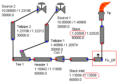
Previous post "Several Criteria and Constraints for Flare Network - Process" has discussed several major important criteria and constraints related flare system. In particular, back pressure is critical to performance of pressure relief valve (PRV) from capacity and stability aspect. Back pressure at PRV is typically back calculated from flare tip, main header, sub-header and finally tail pipe. Isothermal equation may be used for flare pipe pressure drop calculation for conservatism.AFSA or FLARENET is commonly used for flare network modeling. In calculating back pressure at the PRV, flare tip pressure drop is required. In some flare system, i.e. Refinery flare system, a water seal is provided at the bottom of stack to minimum air ingress into main flare system. This water seal (subject to design) may induce a rather fix pressure drop to the back pressure estimation, in particular to very low pressure system i.e. sour gas flare.
How shall engineer create a constant pressure drop in AFSA / FLARENET model ?
One of the way is to use the "Flow Bleed" component. "Flow Bleed" is normally use for fix flow splitter with a fix pressure drop. In this case, introduce a "Flow Bleed" component with following setting
- Offtake Multiplier set to zero (0)
- Offtake Offset set to zero (0)
- Pressure drop set to intended pressure drop
Related Topic
- Quick Estimate Flare Stack Diameter
- Estimate Subsonic Flare Tip Pressure Drop With Graph Derived Correlation
- Quick Estimate Flare Tip Pressure Drop
- Several Criteria and Constraints for Flare Network - Process
- Several Criteria and Constraints for Flare Network - Piping
- Provide More than One Flare KOD in SERIES
Monday, May 4, 2009
Display problem ? Click HERE
Recommended :
- Tips on Succession in FREE Subscription
- Subscribe FREE - Chemical Processing
Qatar LNG production train presently is the world no.1 in term of production rate per train (about 7.8 MTPA compare to "nowadays normal train production of 4 MTPA). With it 7 trains (3 small and 4 large) LNG production in Qatar gas and another few trains in Rasgas have pushed Qatar as world no.1 in term of production.
LNG is normally stored in atmorpsheric tank at LNG liquid temperature of about -160 degC. More information about LNG in "LNG and Supply Chain", safety related in "LNG SES Issues..." and several ways to achieve LNG storage temperature of -160 degC in "Techniques to Achieve Cryogenic Temperature".
Recently received a batch of photos from reader of this blog. They are story related to Qatar Raslaffan LNG storage Boil-off gas (BOG) area...
- Tips on Succession in FREE Subscription
- Subscribe FREE - Chemical Processing
Qatar LNG production train presently is the world no.1 in term of production rate per train (about 7.8 MTPA compare to "nowadays normal train production of 4 MTPA). With it 7 trains (3 small and 4 large) LNG production in Qatar gas and another few trains in Rasgas have pushed Qatar as world no.1 in term of production.LNG is normally stored in atmorpsheric tank at LNG liquid temperature of about -160 degC. More information about LNG in "LNG and Supply Chain", safety related in "LNG SES Issues..." and several ways to achieve LNG storage temperature of -160 degC in "Techniques to Achieve Cryogenic Temperature".
Recently received a batch of photos from reader of this blog. They are story related to Qatar Raslaffan LNG storage Boil-off gas (BOG) area...


Plant safety is important...Believe plant security equally important...
Related Post
- Vacuum Collapse...
- Communication Breakdown...Key to Failure...
- "Fire from Ice" - Lesson Learned & Key Recommendations
- Compressed Gas Incident - Awareness & Learning Fundamentals...
- Pipeline rupture In Varanus Island
- Break the Rules... Pay the Price...
- Vacuum Hazard - Another Catastrophic Factor...
Labels: Accident, Safety, Security
Friday, May 1, 2009
Display problem ? Click HERE
Recommended :
- Tips on Succession in FREE Subscription
- Subscribe FREE - Chemical Processing
Vaccum hazard is potentially a hazard and damaging factor to many pressure vessel. Vacuum should be addressed and extra caution to be taken during design, construction, operation and maintenance to avoid catastrophic failure.
In previous posts, "Vacuum Hazard - Another Catastrophic Factor..." discussed about the damage of vacuum, main factors resulting Vacuum and several scenario may lead to Vacuum Hazard. "4-steps Approach to Combat Vacuum Hazard" discuss about approach may be taken to minimize and avoid Vacuum Hazard. "How powerful is ATMOSPHERIC ?" also has presented a video clip demonstrates how powerful is ATMOSPHERIC pressure and how quick a "vessel" collapse.
This post will share a screen shot of rail car collapsed due to vacuum condition. The rail car had been steamed out and remained hot inside when it started to rain. Quick cooling due to rain running on the rail car and lead to generation of vacuum.
- Tips on Succession in FREE Subscription
- Subscribe FREE - Chemical Processing
Vaccum hazard is potentially a hazard and damaging factor to many pressure vessel. Vacuum should be addressed and extra caution to be taken during design, construction, operation and maintenance to avoid catastrophic failure.In previous posts, "Vacuum Hazard - Another Catastrophic Factor..." discussed about the damage of vacuum, main factors resulting Vacuum and several scenario may lead to Vacuum Hazard. "4-steps Approach to Combat Vacuum Hazard" discuss about approach may be taken to minimize and avoid Vacuum Hazard. "How powerful is ATMOSPHERIC ?" also has presented a video clip demonstrates how powerful is ATMOSPHERIC pressure and how quick a "vessel" collapse.
This post will share a screen shot of rail car collapsed due to vacuum condition. The rail car had been steamed out and remained hot inside when it started to rain. Quick cooling due to rain running on the rail car and lead to generation of vacuum.

