Friday, January 30, 2009
Display problem ? Click HERE
Recommended :
- Tips on Succession in FREE Subscription
- Subscribe FREE - Chemical Processing

A contractor engineer has sized an air receiver with 1000 Sm3/h and client engineer has rechecked the air receiver size. It was found that the basic parameters such as flowrate, operating pressure and temperature, etc are same, however air receiver size calculated by contractor engineer is different than client engineer. After several round of discussion, they found both engineers calculation method are same.
Different Defintion
A detail analysis on both calculations found that the definition of "Standard" condition are different between the contractor engineer and client engineer. Contractor engineer has used 1.01325 bara @ 0 degC (stated in contractor design manual) whilst client engineer has used 1.01325 @ 25 degC (stated in client common requirement manual). Above situation is pretty common discrepancies in design and engineering. Although both engineers talk about the same thing, "Normal" condition, the results may not be the same due the differences in definition. Thus, it is a good engineering practice to write down the defintion clearly in the calculation note or in a common design basis document.
Following are a list of "Standard" condition for several organizations :
In SI Unit :
SI & US Custom
Another factor may also cause the descrepancies is the reference unit. The defintion in SI unit may NOT same as US custom unit eventhough within an organization. For example, SPE defined Standard condition as
Conversion between two different "Normal" condition
Let take above example, 1000 Sm3/h as defined by contractor. What is the equivalent flow (Sm3/hr) for client engineer ?
Contractor manual : 1.01325 bara @ 0 degC
Client manual : 1.01325 @ 25 degC
Equation for conversion can be taken from discussion in "Relate Normal to Actual Volumtric Flow"
Q2 = (z2/z1) x (T2/T1) x (P1/P2) x Q1 .....[1]
where
Q1 & Q2 are Volumetric Flow in m3/h for condition 1 & 2
P1 & P2 are Pressure in bar abs for condition 1 & 2
T1 & T2 are Temperature in K for condition 1 & 2
z1 & z2 are compressibility factor for condition 1 & 2
Condition 1 : 1.01325 bara @ 0 degC (Contractor manual)
Condition 2 : 1.01325 bara @ 25 degC (Client manual)
Assume z1 = z2 = 1
Q1 = 1000 Nm3/h @ Condition 1
From [1],
==> Q2 = (z2/z1) x (T2/T1) x (P1/P2) x Q1
==> Q2 = (298.15 / 273.15) x 1000
==> Q2 = 1091.525 m3/h
The equivalent flow for 1000 Sm3/h @ condition 1 = 1091.525 Sm3/h @ Condition 2. Client engineer shall use 1091.525 Sm3/h in his/her calculation.
Related Post
- Tips on Succession in FREE Subscription
- Subscribe FREE - Chemical Processing
A contractor engineer has sized an air receiver with 1000 Sm3/h and client engineer has rechecked the air receiver size. It was found that the basic parameters such as flowrate, operating pressure and temperature, etc are same, however air receiver size calculated by contractor engineer is different than client engineer. After several round of discussion, they found both engineers calculation method are same.
What is the factor cause the difference ?
Different Defintion
A detail analysis on both calculations found that the definition of "Standard" condition are different between the contractor engineer and client engineer. Contractor engineer has used 1.01325 bara @ 0 degC (stated in contractor design manual) whilst client engineer has used 1.01325 @ 25 degC (stated in client common requirement manual). Above situation is pretty common discrepancies in design and engineering. Although both engineers talk about the same thing, "Normal" condition, the results may not be the same due the differences in definition. Thus, it is a good engineering practice to write down the defintion clearly in the calculation note or in a common design basis document.
Following are a list of "Standard" condition for several organizations :
In SI Unit :
- EPA - 1.01325 bara @ 25 degC
- NIST - 1.01325 bara @ 20 degC
- IUPAC - 1.0 bara @ 0 degC
- ISA - 1.01325 @ 15 degC
- SATP - 1.0 @ 25 degC
- CAGI - 1.0 bara @ 20 degC
- SPE - 1.0 bara @ 15 degC
- SHELL - 1.01325 @ 25 degC
- EXXON - 1.01325 @ 15 degC
- SPE - 14.696 psia @ 60 degF
- OSHA - 14.696 psia @ 60 degF
- OPEC - 14.73 psia @ 60 degF
- ISO 2314 - 14.696 psia @ 59 degF
- ISO 3977-2 - 14.696 psia @ 59 degF
- U.S. Army - 14.503 psia @ 59 degF
SI & US Custom
Another factor may also cause the descrepancies is the reference unit. The defintion in SI unit may NOT same as US custom unit eventhough within an organization. For example, SPE defined Standard condition as
- 1.0 bara @ 15 degC in SI unit
- 14.696 psia @ 60 degF in US custom unit
Conversion between two different "Normal" condition
Let take above example, 1000 Sm3/h as defined by contractor. What is the equivalent flow (Sm3/hr) for client engineer ?
Contractor manual : 1.01325 bara @ 0 degC
Client manual : 1.01325 @ 25 degC
Equation for conversion can be taken from discussion in "Relate Normal to Actual Volumtric Flow"
Q2 = (z2/z1) x (T2/T1) x (P1/P2) x Q1 .....[1]
where
Q1 & Q2 are Volumetric Flow in m3/h for condition 1 & 2
P1 & P2 are Pressure in bar abs for condition 1 & 2
T1 & T2 are Temperature in K for condition 1 & 2
z1 & z2 are compressibility factor for condition 1 & 2
Condition 1 : 1.01325 bara @ 0 degC (Contractor manual)
Condition 2 : 1.01325 bara @ 25 degC (Client manual)
Assume z1 = z2 = 1
Q1 = 1000 Nm3/h @ Condition 1
From [1],
==> Q2 = (z2/z1) x (T2/T1) x (P1/P2) x Q1
==> Q2 = (298.15 / 273.15) x 1000
==> Q2 = 1091.525 m3/h
The equivalent flow for 1000 Sm3/h @ condition 1 = 1091.525 Sm3/h @ Condition 2. Client engineer shall use 1091.525 Sm3/h in his/her calculation.
Related Post
Labels: Fluid Flow, Unit
Wednesday, January 28, 2009
Recommended :
- Subscribe FREE - Energy Biz
- Tips on Succession in FREE Subscription
 Sulzer Chemtech, similar to Koch-Glitch (KG) is another world column internal manufacturer and providing advanced mass transfer and static mixing solutions to plant worldwide. Typical internals supply by Sulzer are trays, structured and random packings, internals for separation columns. More detail can be found here.
- Subscribe FREE - Energy Biz
- Tips on Succession in FREE Subscription
Sulzer Chemtech, similar to Koch-Glitch (KG) is another world column internal manufacturer and providing advanced mass transfer and static mixing solutions to plant worldwide. Typical internals supply by Sulzer are trays, structured and random packings, internals for separation columns. More detail can be found here.Sulzer provide FREE Hydrauic Design Program (SULCOL) for Structured and Random Packings, and Trays. In previous version (SULCOL 1.0), two programs SULTRAY and SULPACK are merged into SULCOL 1.0. Sulzer has just realease it latest version, SULCOL 2.0.
New Features
SULCOL 2.0 have included following new faetures :
- Multiple loads for tray design
- New print format for trays and packings
- Export of the Excel file for packing (as in Sulpak)
- Enhanced Section Handling
- New ring type: C-Ring
- Extended default settings in Preferences
Features available in previous version are :
- Structured and random packing hydraulic design and rating
- Tray hydraulic design and rating
- Import input data from PRO II, ASPENPLUS, SULPACK EXCEL-File, SULTRAYFile
- Export data in RTF, XML, XLS
In comparison, KG-TOWER can be downloaded once you have registered.
To own a FREE SULCOL, you need to apply and it take several days for approval.
Click here to APPLY.
Source : Sulzer Chemtech
Click here to APPLY.
Source : Sulzer Chemtech
- FREE KG-TOWER V4
- Packed Column...sometime better than tray column
- High Pressure High Liquid Loading Distillation
- Jaeger Inc., many of us may already aware of this packing & column internal manufacturer
- Distillation Pilot Plant Design, Operating Parameters and Scale-up Considerations
- TAC - High Temperature Simulated Distillation (HTSD) and Petroleum Characterization...
- Operation and Control of Azeotropic Distillation Column Sequences
Labels: Column, Fractionation, Packed Column, Packing
Sunday, January 25, 2009
Display problem ? Click HERE
Recommended :
Subscribe FREE - Processing Magazine
 Depressuring system is provided in Oil and gas, Gas & LNG plant, etc to evacuate the inventory from process system as fast as possible so that the reduced internal pressure stresses is kept below the rupture stress. This has been discussed in "Depressuring within 15 minutes no longer applicable ?". Nevertheless, quick depressuring may lead to other problem such as low temperature embrittlement, excessive noise and vibration, etc. Depressure a high pressure would lead to low temperature of depressured system and failure due to low temperature embrittlement. Higher the depressuring rate, lower the temperature can be experienced by depressured system. Thus, the restriction orifice (RO) downstream of Blowdown Valve (BDV) in depressuring system primarily is to limit flow so that the temperature will not drop below the allowable lowest temperature limit of material. This has been discussed in "Don't misunderstood depressuring".
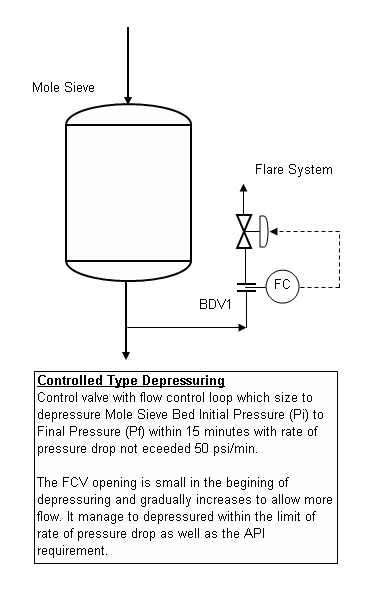
Although depressuring shall be implemented within the shortest time possible, excessive depressuring may potentially lead to damage to equipment such as compressor seal, solid bed, etc. Thus, there are two type of depressuring as discussed in "Controlled and Non-controlled Type Depressuring". Nevertheless, it is emphasized again here, depressuring system shall be designed to bring plant to safe level without any tolerance.
Many depressuring systems are designed to depressure the system within 15 minutes follow recommendation in API 521. Nevertheless, one shall take note that the 15 minutes is sort of arbitrary and may be good for some system and configuration. Thus, in most recent API STD 521, the requirement has slightly changed where a depressuring system shall be designed such that the stress induced by internal pressure of a system is lower than stress allowable by the system. This may lead to shorter depressuring time as discussed in "Depressuring within 15 minutes no longer applicable ?".
 Depressuring can be conducted using simple depressuring module in process simulator such HYSYS, PRO-II, etc. One shall understood there are limitation and accuracy issue in above mentioned depressuring modules and shall be used with care. There are other depressuring simulator such as LNGDYN by TECHNIP, BLOWDOWN by Imperial College, etc which are calculated rigorously and tested with real plant data. It is always advisable to use these simulator for specific case.
Assumption
In this post, a manual depressuring method is introduced. This method is first introduced by Grote and are derived base on following assumptions :
i) Critical flow throughout entire depressuring process
ii) Constant mass flow throughout entire depressuring process
iii) System being depressured is maintained as gaseous throughout entire depressuring process
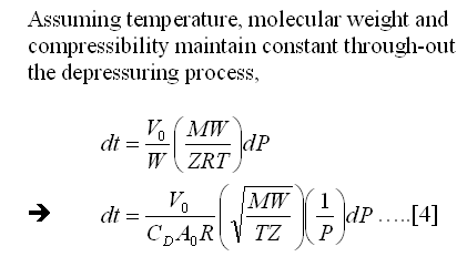
iv) Constant temperature, molecular weight and compressibility
Methodology
Following is the derivation of the manual equation.
Subscribe FREE - Processing Magazine
Depressuring system is provided in Oil and gas, Gas & LNG plant, etc to evacuate the inventory from process system as fast as possible so that the reduced internal pressure stresses is kept below the rupture stress. This has been discussed in "Depressuring within 15 minutes no longer applicable ?". Nevertheless, quick depressuring may lead to other problem such as low temperature embrittlement, excessive noise and vibration, etc. Depressure a high pressure would lead to low temperature of depressured system and failure due to low temperature embrittlement. Higher the depressuring rate, lower the temperature can be experienced by depressured system. Thus, the restriction orifice (RO) downstream of Blowdown Valve (BDV) in depressuring system primarily is to limit flow so that the temperature will not drop below the allowable lowest temperature limit of material. This has been discussed in "Don't misunderstood depressuring".Although depressuring shall be implemented within the shortest time possible, excessive depressuring may potentially lead to damage to equipment such as compressor seal, solid bed, etc. Thus, there are two type of depressuring as discussed in "Controlled and Non-controlled Type Depressuring". Nevertheless, it is emphasized again here, depressuring system shall be designed to bring plant to safe level without any tolerance.
Many depressuring systems are designed to depressure the system within 15 minutes follow recommendation in API 521. Nevertheless, one shall take note that the 15 minutes is sort of arbitrary and may be good for some system and configuration. Thus, in most recent API STD 521, the requirement has slightly changed where a depressuring system shall be designed such that the stress induced by internal pressure of a system is lower than stress allowable by the system. This may lead to shorter depressuring time as discussed in "Depressuring within 15 minutes no longer applicable ?".
Depressuring can be conducted using simple depressuring module in process simulator such HYSYS, PRO-II, etc. One shall understood there are limitation and accuracy issue in above mentioned depressuring modules and shall be used with care. There are other depressuring simulator such as LNGDYN by TECHNIP, BLOWDOWN by Imperial College, etc which are calculated rigorously and tested with real plant data. It is always advisable to use these simulator for specific case.Assumption
In this post, a manual depressuring method is introduced. This method is first introduced by Grote and are derived base on following assumptions :
i) Critical flow throughout entire depressuring process
ii) Constant mass flow throughout entire depressuring process
iii) System being depressured is maintained as gaseous throughout entire depressuring process
iv) Constant temperature, molecular weight and compressibility
Methodology
Following is the derivation of the manual equation.


Concluding Remark
Equation [5] may be used for manual depressuring if a system inventory (initial mass, M0), depressuring time (t), initial (P0) and final pressure (P) are are known. One shall check the assumptions are valid before it is used. This equation may be used as quick method to determine the depressuring flowrate for quick estimate, however it is not recommended during detailed design.
Equation [5] may be used for manual depressuring if a system inventory (initial mass, M0), depressuring time (t), initial (P0) and final pressure (P) are are known. One shall check the assumptions are valid before it is used. This equation may be used as quick method to determine the depressuring flowrate for quick estimate, however it is not recommended during detailed design.
Related Post
- Additional Concerns in Controlled Depressuring
- Depressuring - Save Some Time in HYSYS - FLARENET Iteration
- Few Recommendation on Manual Blowdown Line
- A refresh to Process Engineer on few phenomenons in restriction orifice
- Bug in ASPENTECH HYSYS 2006 Dynamic Depressuring Fisher Valve model
- How to apply valve equation in HYSYS Depressuring ?
- Why Restriction Orifice is some distance from Blowdown valve ?
Labels: Depressurization, HYSYS
Friday, January 23, 2009
Display problem ? Click HERE

Recommended :Earlier post "Crevice Corrosion Mechanism & Prevention" has briefly discussed mechanism of crevice corrosion and its prevention. As discussed, one of the preventive measures is to select correct material to resist crevice corrosion. Stainless Steel (SS) is known to resist to general corrosion by forming a thin, protective oxide film on it external surface, SS still susceptible to localized corrosion i.e. Chloride stress corrosion cracking (CSCC), crevice corrosion, pitting corrosion, etc once this protective film is partly damage. Stainless steel once expose to water (present of Chloride) with temperature higher than 60 degC, CSCC is potentially occurred. On the other hand, temperature lower than 60 degC, crevice and pitting corrosion is potentially occurred.
There are different grade of Stainless Steel i.e. SS304, SS316, S31803, S32205, etc. How Chloride [Cl] concentration, Sulfate [SO4] concentration, pH level, temperature, oxygen level, etc affecting crevice corrosion for different Stainless Steel ?

The Crevice Corrosion Engineering Guide for Stainless Steels (CCEG) is a program available FREE to check type of Stainless Steel susceptible to crevice corrosion in water under particular conditions and impurities. The CCEG is a program with predictive mathematical model of crevice corrosion to assist with the selection of stainless steels for use in chloride and sulphate containing waters, including sea water. It was jointly developed by Nickel Development Institute (NiDI) and Sheffield Testing Laboratories Ltd.

Application Range
This program has been developed with the following application range :
- Fluid : Water
- Operating temperature : 5 - 85 degC
- Chloride [Cl] concentration : 1-30,000 ppm
- Sulphate [SO4] concentration : 0-10,000 ppm
- Total Dissolved Solids (TDS) concentration : 0 - 65000 ppm or mg/L
- * Can be calculated base on 1.65 [Cl] + [SO4]
- Alkalinity : 0 - 10000 mg/L (as concentration of CaCO3 in mg/L)
- Hardness : 0 - 20000 mg/L (as concentration of CaCO3 in mg/L)
- pH : 5 - 9
The program will check for following material :
- S30400
- S31600
- S31700
- S31803
- S32205
- N08904
- 6% Mo SS
Example
Let take a water with following parameters :
- Chloride (ppm) : 1000
- Sulphate (ppm) : 100
- Hardness (as CaCO3 mg/L) : 100
- Alkalinity (As CaCO3 mg/L) : 100
- TDS (mg/L) : 1798
- pH : 7
- Temp (C) : 25
- Oxygen level (ppm) : 7
Download : Click here to download the program (1.17 MB).
Source : Nickel Development Institute (NiDI)
Related Topics
Labels: Chloride Stress Corrosion Cracking, Corrosion, Corrosion Resistance Material
Wednesday, January 21, 2009
Display problem ? Click HERE
 Simple update to IEM Members or those who are practicing Engineering in MALAYSIA...
Biotechnology is a multi-disciplinary area, encompassing the biological sciences, industrial technology and bioprocess engineering. It involves using living cells or biological catalysts for the production of industrial products and services. Chemical engineers can make a significant contribution in the bioreactor operation and subsequent downstream processing for the separation and recovery of products. Chemical engineers can also help to develop integrated processes for energy and resource recovery to improve existing biotechnological processes.
The talk will cover the important role of chemical engineers in the biotechnology sector, with special emphasis on process substitution for new biotech products and developing appropriate technologies for our local biotechnology industry based on the speaker’s experience.
Date : 03 February 2009 (Tuesday)
Time : 5.30 pm to 7.00 pm
CPD : 2 Hours (approved by BEM)
Venue : IEM Conference Hall A, Bangunan Ingenieur, Petaling Jaya
Speaker : Professor Dr. Mohd Ali Hassan
*Any queries, please contact sec@iem.org.my.
Related Post
The talk will cover the important role of chemical engineers in the biotechnology sector, with special emphasis on process substitution for new biotech products and developing appropriate technologies for our local biotechnology industry based on the speaker’s experience.
A talk on “ROLE OF CHEMICAL ENGINEERS IN BIOTECH SECTOR’”, organized by Chemical Engineering Technical Division, IEM has been scheduled.
Date : 03 February 2009 (Tuesday)
Time : 5.30 pm to 7.00 pm
CPD : 2 Hours (approved by BEM)
Venue : IEM Conference Hall A, Bangunan Ingenieur, Petaling Jaya
Speaker : Professor Dr. Mohd Ali Hassan
*Any queries, please contact sec@iem.org.my.
Related Post
Tuesday, January 20, 2009
Display problem ? Click HERE
Recommended :
- Subscribe FREE - Energy Biz
- Tips on Succession in FREE Subscription
Koch-Glitsch (KG) is one the world’s largest manufacturer of mass transfer equipment internal i.e. structural packing, random packing, tray, column internals, etc. If you have ever involved in design ang operation of plant with column, you probably aware of KG-TOWER. KG has just released it column packing hydraulic rating software, KG-TOWER® Equipment Rating Program, version 4 and available FREE for download ! KG-TOWER assist process engineer in designing a new column internal and rating of existing column internal. The internal includes those conventional tray, high performance valve trays (by KG), conventional and high performance random and structured tower packings.
New Feartures & Improvement
In the new release (ver. 4), new feature and improvments include :
Source : Koch-Glitsch (KG)
Related Topic
- Subscribe FREE - Energy Biz
- Tips on Succession in FREE Subscription
Koch-Glitsch (KG) is one the world’s largest manufacturer of mass transfer equipment internal i.e. structural packing, random packing, tray, column internals, etc. If you have ever involved in design ang operation of plant with column, you probably aware of KG-TOWER. KG has just released it column packing hydraulic rating software, KG-TOWER® Equipment Rating Program, version 4 and available FREE for download ! KG-TOWER assist process engineer in designing a new column internal and rating of existing column internal. The internal includes those conventional tray, high performance valve trays (by KG), conventional and high performance random and structured tower packings.New Feartures & Improvement
In the new release (ver. 4), new feature and improvments include :
- Sieve tray design/rating capability
- Updated tray models
- Support for PRO/II 8.1 files in Simulation import feature
- Ability to rate INTALOX® ULTRA™ Random Packing & FLEXIGRID® severe service packing sizes
- Ability to specify minimum and maximum loadings
- More tray definition sketches
- Updated Help files, including more support for the simulation import feature
- Updated sales contact and technical help information
Source : Koch-Glitsch (KG)
Related Topic
- Packed Column...sometime better than tray column
- High Pressure High Liquid Loading Distillation
- Jaeger Inc., many of us may already aware of this packing & column internal manufacturer
- Distillation Pilot Plant Design, Operating Parameters and Scale-up Considerations
- TAC - High Temperature Simulated Distillation (HTSD) and Petroleum Characterization...
- Operation and Control of Azeotropic Distillation Column Sequences
Labels: Column, Fractionation, Packed Column, Packing
Saturday, January 17, 2009
Display problem ? Click HERE
Recommended :
- Subscribe FREE - Energy Biz
- Tips on Succession in FREE Subscription
Crevice is location /area / space where normal fluid has less contact and access with it. Typical example of crevice are gaps between parts, space between gaskets and bolt, inside seals, inside cracks due to external impact or scratches, spaces filled with deposits, plastic paper lay on the metal plate, etc. In crevice, the environment is different than area expose to normal fluid. For example, gasket with bolt. Bolt surface expose to atmosphere is oxygen rich while wet air trapped between bolt and gasket is stagnant and with limited oxygen. Localized corrosion occur in the crevice is called crevice corrosion.
Crevice Corrosion Example
Following is an example of crevice corrosion at pipe support.

Crevice corrosion is pretty similar to pitting corrosion as discussed in "Pitting Corrosion - Mechanism & Prevention".

Mechanism
A metal surface with gasket at shown above will potentially experience crevice corrosion. Oxygen rich fluid enters crevice between gasket and metal surface.
- Genenal Oxidation Corroion
Normal corrosion (general oxidation corrosion) will occur through the metal surface outside and inside the crevice. As oxygen in trapped fluid consumed oxygen, environment within crevice is deoxygenated (low in oxygen level) increases the potential difference between crevice environment and oxygen rich environment.
Metal (E.g. FE) surface (expose to atmosphere) is oxygen rich will becomes the cathode whilst the metal surface in the crevice (gasket contacted area) is low in oxygen level will becomes anode. This form a complete circuit where metal at the crevice (FE) will be ionized to release electron (e) and form ion Ferum (FE2+), this electron will travel to the metal surface expose to atmosphere to react with Oxygen (O2) and water (H2O) to form ion hydroxides (OH-). Ion Ferum (FE2+) will react with ion hydroxides (OH-) to form Ferum Oxide (Fe2O3) which typically a brown rust.
- Increases Acidity in Crevice Environment
The ions FE2+ formed potentially hydrolyze water (H2O) in tapped fluid and produced positive ion (i.e. H+) and FE (corrosion product). The corrosion product will further block the movement of trapped fluid and increase the corrosion potential. The H+ will further increase the acidity of the trapped fluid and this severely increases corrosivity of trapped fluid.
- Other Corrosion i.e. CSCC
Production of ion positive (H+) will also attract negative ions i.e Chlorides, Sulfates, etc outside crevice travel into the trapped fluid in crevice, accumulation of these negative ions will potentially results Chloride and Sulfate associated corrosion such Chloride stress corrosion cracking (CSCC).
Preventive measures
There are several preventive measures to minimize crevice corrosion.
i) Avoid / minimize crevices during design stage i.e. keep junction points as wide open as possible.
ii) Avoid / Minimise crevices during fabrication i.e. smooth weld
iii) Avoid / minimize solution get into crevice i.e. greasing bolt / nut
iv) Use high resistance material (high PRE material)
v) Avoid / Minimise crevices during operation. Scale settled on metal surface will form "crevice" and trapped fluid. Routine cleaning to remove scale is one of the effective way to minimise crevices.
vi) Avoid/ Minimize objects i.e plastic bag put on metal surface.
vii) External coating
Related Topics
- Subscribe FREE - Energy Biz
- Tips on Succession in FREE Subscription
Crevice is location /area / space where normal fluid has less contact and access with it. Typical example of crevice are gaps between parts, space between gaskets and bolt, inside seals, inside cracks due to external impact or scratches, spaces filled with deposits, plastic paper lay on the metal plate, etc. In crevice, the environment is different than area expose to normal fluid. For example, gasket with bolt. Bolt surface expose to atmosphere is oxygen rich while wet air trapped between bolt and gasket is stagnant and with limited oxygen. Localized corrosion occur in the crevice is called crevice corrosion.Crevice Corrosion Example
Following is an example of crevice corrosion at pipe support.

Crevice corrosion is pretty similar to pitting corrosion as discussed in "Pitting Corrosion - Mechanism & Prevention".

Mechanism
A metal surface with gasket at shown above will potentially experience crevice corrosion. Oxygen rich fluid enters crevice between gasket and metal surface.
- Genenal Oxidation Corroion
Normal corrosion (general oxidation corrosion) will occur through the metal surface outside and inside the crevice. As oxygen in trapped fluid consumed oxygen, environment within crevice is deoxygenated (low in oxygen level) increases the potential difference between crevice environment and oxygen rich environment.
Metal (E.g. FE) surface (expose to atmosphere) is oxygen rich will becomes the cathode whilst the metal surface in the crevice (gasket contacted area) is low in oxygen level will becomes anode. This form a complete circuit where metal at the crevice (FE) will be ionized to release electron (e) and form ion Ferum (FE2+), this electron will travel to the metal surface expose to atmosphere to react with Oxygen (O2) and water (H2O) to form ion hydroxides (OH-). Ion Ferum (FE2+) will react with ion hydroxides (OH-) to form Ferum Oxide (Fe2O3) which typically a brown rust.

- Increases Acidity in Crevice Environment
The ions FE2+ formed potentially hydrolyze water (H2O) in tapped fluid and produced positive ion (i.e. H+) and FE (corrosion product). The corrosion product will further block the movement of trapped fluid and increase the corrosion potential. The H+ will further increase the acidity of the trapped fluid and this severely increases corrosivity of trapped fluid.
- Other Corrosion i.e. CSCC
Production of ion positive (H+) will also attract negative ions i.e Chlorides, Sulfates, etc outside crevice travel into the trapped fluid in crevice, accumulation of these negative ions will potentially results Chloride and Sulfate associated corrosion such Chloride stress corrosion cracking (CSCC).
Preventive measures
There are several preventive measures to minimize crevice corrosion.
i) Avoid / minimize crevices during design stage i.e. keep junction points as wide open as possible.
ii) Avoid / Minimise crevices during fabrication i.e. smooth weld
iii) Avoid / minimize solution get into crevice i.e. greasing bolt / nut
iv) Use high resistance material (high PRE material)
v) Avoid / Minimise crevices during operation. Scale settled on metal surface will form "crevice" and trapped fluid. Routine cleaning to remove scale is one of the effective way to minimise crevices.
vi) Avoid/ Minimize objects i.e plastic bag put on metal surface.
vii) External coating
Related Topics
Labels: Chloride Stress Corrosion Cracking, Corrosion, Corrosion Resistance Material
Wednesday, January 14, 2009
Display problem ? Click HERE

Stainless steel is one type of material commonly used in oil & gas, refinery, petrochemical, pharmaceutical industries. Stainless steel is a material does not stain and corrosion resistance to many fluids. Stainless steel is rather "soft" and infact it is a cavitation resistance material. This has been discussed in "Stainless Steel SS316 resist to CAVITATION ?".
Recommended :
- Subscribe FREE - Processing Magazine
- Tips on Succession in FREE Subscription
Although Stainless steel is corrosion resistance to many corrosive fluids by formation of protective oxide film, it is still susceptible to pitting corrosion, one of the most destructive forms of corrosion which potentially cause equipment failures on perforation / penetration as discussed in "Pitting Corrosion - Mechanism & Prevention".
Beside pitting corrosion, stainless steel also susceptible to Chloride Stress Corrosion Cracking (CSCC) as discussed in "Chloride Stress Corrosion Cracking & Use correct MOC for seawater service". CSCC is initiation and propagation of cracks in a metal or alloy under tensile stresses and a corrosive environment contains Chloride compounds. Once the crack is initiated, it will propagate rapidly and potentially lead to catastrophic failure. There are more discussion on stainless steel can be found here.
Recommended :
- Subscribe FREE - Processing Magazine
- Tips on Succession in FREE Subscription
Although Stainless steel is corrosion resistance to many corrosive fluids by formation of protective oxide film, it is still susceptible to pitting corrosion, one of the most destructive forms of corrosion which potentially cause equipment failures on perforation / penetration as discussed in "Pitting Corrosion - Mechanism & Prevention".Beside pitting corrosion, stainless steel also susceptible to Chloride Stress Corrosion Cracking (CSCC) as discussed in "Chloride Stress Corrosion Cracking & Use correct MOC for seawater service". CSCC is initiation and propagation of cracks in a metal or alloy under tensile stresses and a corrosive environment contains Chloride compounds. Once the crack is initiated, it will propagate rapidly and potentially lead to catastrophic failure. There are more discussion on stainless steel can be found here.
Dr. David Jenkinson, Director of Nickel Institute has produced a series online training modules on "An Introduction to Selection of Stainless Steels for Corrosion Resistance". The online training modules are in audio format which can be read while listen to the explanation. Visual plus audio will quickly assist engineers in understanding the contents.
Click here to begin learning Stainless Steel and It Selection.
Following are complete listing of training module for Stainless Steel and It Selection.
01 - Disclaimer
02 - Module Abstract
03 - Module Information
04 - Chemical Symbols
05 - What Will We Cover?
06 - What Will We Cover? - What is Stainless Steel?
07 - How Stainless Steel Works
08 - Chromium is the Basic Building Block of Stainless Steels
09 - Damage to the Protective Oxide Film
10 - Penetration of the Protective Oxide Film
11 - Corrosion of Embedded Iron in a Stainless Steel Pipe Bend
12 - The protective passive film can be damaged mechanically or chemically in various ways.
13 - What Will We Cover? - Effect of Alloying Additions
14 - Effect of Alloying Additions
15 - 1. Corrosion Resistance
16 - Effect of Alloying Elements on Corrorsion Resistance - Chromium
17 - Effect of Chromium on Atmospheric Corrosion of Steels
18 - Pitting Resistance Equivalent Number (PRE)
19 - Effect of Alloying Elements on Corrosion Resistance - Nickel
20 - Addition of Nickel
21 - Nickel Provides Resistance to Reducing Chemicals
22 - Effect of Alloying Elements on Corrorsion Resistance - Molybdenum
23 - Effect of Alloying Elements on Corrorsion Resistance - Nitrogen
24 - Effect of Alloying Elements on Corrorsion Resistance - Carbon
25 - Hibernia Oil Production Platform
26 - 2. Crystal Structure
27 - Ferritic Stainless Steels
28 - Adding Nickel to Stainless Steels
29 - Austenitic Stainless Steel
30 - Duplex Stainless Steels
31 - List of Ferrite & Austenite Formers
32 - When Choosing a Stainless Steel
33 - What Will We Cover? - Families of Stainless Steels
34 - Families of Stainless Steels
35 - Ferritic Stainless Steels
36 - Typical Compositions of Common Stainless Steels
37 - Type 409 is hte most widely used ferritic stainless steel.
38 - Proprietary Grades
39 - Dishwashers
40 - Stainless Steel Refrigerators
41 - Hot Water Tank
42 - Austenitic Stainless Steels
43 - Typical Compositions of Common Stainless Steels
44 - Domestic Kitchen Sink
45 - Parliament House, Canberra, Australia
46 - Type 304 Stainless Steel Beer Kegs
47 - Chemical Plant
48 - Frederick R. Weisman Art Museum
49 - Wet Electrostatic Precipitator
50 - Duplex Stainless Steels
51 - Typical Compositions of Common Stainless Steels
52 - Type 316LN Stainless Steel - Example
53 - Pressurized Peroxide Reactor
54 - Stainless Steel Meat Racks
55 - Elevator Tower
56 - Families of Stainless Steels
57 - Martensitic Stainless Steels
58 - Typical Compositions of Common Stainless Steels
59 - Stainless Steel Products - Examples
60 - Martensitic Stainless Steel Blades
61 - Precipitation Hardening (PH) Stainless Steels
62 - Typical Compositions of Common Stainless Steels
63 - High Strength S45000 Precipitation Hardening Stainless Steel
64 - What Will We Cover? - Maximizing Corrosion Resistance
65 - Corrosion of Carbon Steel
66 - General Corrosion
67 - Localized Corrosion
68 - Pitting
69 - Once it gets started, pitting is difficult to stop and to repair.
70 - PRE Numbers for Some Ferritic, Austenitic & Duplex Grades
71 - Pitting Corrosion - Effect of Temperature and Chloride Level
72 - Crevice Corrosion
73 - Crevice Corrosion - Example
74 - Chloride Stress Corrosion Cracking (SCC)
75 - Chloride Stress Corrosion Cracking - Example
76 - Copson Curve
77 - Chloride Stress Corrosion Cracking - Effect of Temperature and Chloride Level
78 - What Will We Cover? - High Performance Stainless Steels
79 - High Performance Stainless Steels
80 - Pitting and Crevice Corrosion Resistance
81 - Three Families of High Performance Stainless Steels
82 - PRE Numbers for Some Ferritic, Austenitic & Duplex Grades
83 - Immersed in Seawater Without Cathodic Protection
84 - Heat Exchanger
85 - Flexible Hosing
86 - Heat Exchanger for Aggressive Chloride Service
87 - Zeron 100 Fittings
88 - Condenser Tubes
89 - What Will We Cover? - Nickel Alloys
90 - More Resistant Alloys
91 - Nickel Alloys
92 - Alloy C-276
93 - Summary
Further Reading
- Chloride Stress Corrosion Cracking & Use correct MOC for seawater service
- Pitting Corrosion - Mechanism & Prevention
- How Chloride stress corrosion cracking Lookslike ?
- Different Equation for Pitting Resistance Equivalent Number (PREN)
- Unified Numbering System for Metals and Alloys
Labels: Chloride Stress Corrosion Cracking, Corrosion Resistance Material, Material
Monday, January 12, 2009
Display problem ? Click HERE

FREE Chemical Engineering Digital Issue for Jan 2009 has just been released !
Interesting articles for this month :
A Primer On Coal-to-Liquids
Converting coal to liquid fuels is one option China and the U.S. are pursing
Tray Column Design
This one-page guide presents criteria needed for the effective specification of trays for a distillation or stripping column
Controlling Emissions With Ceramic Filters
Ceramic filters are well suited for high-temperature processes that are subject to strict emissions limits, including those for dioxins
Active Management of Pipespool Fabricators
Contractors need to integrate and engage to improve deliveries and shorten project schedules
Mechanical Carbon In Chemical Processing Equipment
This self-lubricating material offers advantages when used for components that are running submerged in the process fluid
CSTRs: Bound for Maximum Conversion
A design approach for continuous stirred-tank reactors is developed for both reversible and irreversible second-order reactions
TIPS
If you are subscriber, you may access previous digital releases (July 2008 - Dec 2008). Learn more in "How to Access Previous Chemical Engineering Digital Issue".
If you yet to be subscriber of Chemical Engineering, requested your FREE subscription via this link (click HERE). Prior to fill-up the form, read "Tips on Succession in FREE Subscription".
Related Post
Chemical Engineering magazine has just released Jan 2009 issue. If you are the subscriber of Chemical Engineering, you should have received similar notification.
***********************
Interesting articles for this month :
A Primer On Coal-to-Liquids
Converting coal to liquid fuels is one option China and the U.S. are pursing
Tray Column Design
This one-page guide presents criteria needed for the effective specification of trays for a distillation or stripping column
Controlling Emissions With Ceramic Filters
Ceramic filters are well suited for high-temperature processes that are subject to strict emissions limits, including those for dioxins
Active Management of Pipespool Fabricators
Contractors need to integrate and engage to improve deliveries and shorten project schedules
Mechanical Carbon In Chemical Processing Equipment
This self-lubricating material offers advantages when used for components that are running submerged in the process fluid
CSTRs: Bound for Maximum Conversion
A design approach for continuous stirred-tank reactors is developed for both reversible and irreversible second-order reactions
***********************
TIPS
If you are subscriber, you may access previous digital releases (July 2008 - Dec 2008). Learn more in "How to Access Previous Chemical Engineering Digital Issue".
If you yet to be subscriber of Chemical Engineering, requested your FREE subscription via this link (click HERE). Prior to fill-up the form, read "Tips on Succession in FREE Subscription".
Related Post
- How to Access Previous Chemical Engineering Digital Issue
- 3 Most Important & FREE Magazines That I Read...
- Non - Technical Quick References for a Chemical & Process Engineers
- R&D engineer, Academician and Student...Don't miss this !
- More You Share More You Learn
- Knowledge is Own by Everyone but Not Someone
- Tips on Succession in FREE Subscription
Labels: E-Doc, Education, Learning
Sunday, January 11, 2009
Display problem ? Click HERE
Recommended :
- Subscribe FREE - Processing Magazine
- Tips on Succession in FREE Subscription
Earlier posts "Quick Estimation of CO2 Corrosion Rate", "CO2 Corrosion Rate Estimation Using M-506 Model" and "CO2 Corrosion Using Freecorp Model", the DeWaard Milliam model, Norsok M-506 model and FREECORP models have been introduced. All these corrosion estimation models are available FREE for all. Corrosion allowance (CA) is provided in pipeline / piping to cater for required design life. Low corrosion rate (CR) will require low CA. For high CR, higher CA is provided. In many events, corrosion inhibitor (CI) is injected into corrosive in order to reduce CR. Although low CA with CI injection, CI would incur high operation cost. Thus, a life cycle cost (LCC) study will require to be conducted to determining he cost effective option in provision of normal material with CA plus CI or Corrosion Resistance Material (CRA).
- Subscribe FREE - Processing Magazine
- Tips on Succession in FREE Subscription
Earlier posts "Quick Estimation of CO2 Corrosion Rate", "CO2 Corrosion Rate Estimation Using M-506 Model" and "CO2 Corrosion Using Freecorp Model", the DeWaard Milliam model, Norsok M-506 model and FREECORP models have been introduced. All these corrosion estimation models are available FREE for all. Corrosion allowance (CA) is provided in pipeline / piping to cater for required design life. Low corrosion rate (CR) will require low CA. For high CR, higher CA is provided. In many events, corrosion inhibitor (CI) is injected into corrosive in order to reduce CR. Although low CA with CI injection, CI would incur high operation cost. Thus, a life cycle cost (LCC) study will require to be conducted to determining he cost effective option in provision of normal material with CA plus CI or Corrosion Resistance Material (CRA).For the CA plus CI injection option, one of the factor shall be taken into account in determining CA is the availability of corrosion inhibition. There are many events would lead to corrosion inhibition unavailable i.e. maintenance, nonscheduled trip, deficiency of inhibition, unexpected flow, etc. Following is a simple method in determining the CA by consideration of Availability.
where :
CA = Corrosion rate
t = Design life
ICR = Inhibited Corrosion Rate
UCR = Uninhibited Corrosion Rate
Example :
A pipeline is design for 25 years, the corrosion rate is about 3 mm/year. High corrosion allowance (25 x 3 = 75 mm) is required and this has lead to injection of Corrosion Inhibition (CI) to reduce the corrosion rate to 0.3 mm/year. It is expected the availability of corrosion inhibition facilties is about 90%. Calculate CA required with CI injection.
t = 25
ICR = 0.3 mm / year
UCR = 3 mm / year
Av = 90%
CA = t x [ICR x Av + UCR x (1 - Av)]
CA = 25 x [0.3 x 90% + 3.0 x (1-90%)]
CA = 14.25 mm
Required CA is 14.25 mm.
A simple Corrosion Allowance Calculator is ready for download.
Download Corrosion Allowance Calculator (Excel).
Related Post
CA = t x [ICR x Av + UCR x (1 - Av)]
where :
CA = Corrosion rate
t = Design life
ICR = Inhibited Corrosion Rate
UCR = Uninhibited Corrosion Rate
Example :
A pipeline is design for 25 years, the corrosion rate is about 3 mm/year. High corrosion allowance (25 x 3 = 75 mm) is required and this has lead to injection of Corrosion Inhibition (CI) to reduce the corrosion rate to 0.3 mm/year. It is expected the availability of corrosion inhibition facilties is about 90%. Calculate CA required with CI injection.
t = 25
ICR = 0.3 mm / year
UCR = 3 mm / year
Av = 90%
CA = t x [ICR x Av + UCR x (1 - Av)]
CA = 25 x [0.3 x 90% + 3.0 x (1-90%)]
CA = 14.25 mm
Required CA is 14.25 mm.
A simple Corrosion Allowance Calculator is ready for download.
Download Corrosion Allowance Calculator (Excel).
Related Post
Labels: CO2, Corrosion, Corrosion Resistance Material
Friday, January 9, 2009
Display problem ? Click HERE
Recommended :
Three main issues are their concerns : Safety, Environment and Security.
Safety
For the past 40 years, there are more than 25 accidents related to LNG from production plant, storage and transportation.
 Environment Impact
Carbon Dioxide (CO2) is known to create severe greenhouse effect and contribute serious global warming. Many efforts such as Co2 capture and sequestration are in research and implementation in order to minimize release of Co2 to atmospheric. It is aware that 1 mole of methane is about 21 time CO2 equivalent. Those any similar quantity of LNG release would seriously results severe global warming. Again, serious safety, facilities and operational review in place to minimize the potential of LNG release to atmospheric.
Security
Following the terrorist attack to twin tower in 911 case, many security agent has postulated the danger of similar attack to plant with flammable product i.e LNG plant. This is another push to minimize LNG plant implementation. Having say that, similar risk is still applicable to other plant i.e refinery, petrochemical plant, etc. Are we going to stop implementation of all these facilities due to this factor ?
Following are some video clip related danger of LNG.
The Risks & Danger of LNG Liquefied Natural Gas
"LNG is Safe, Clean & Affordable" Liquefied Natural Gas
Another Fire Near LNG Terminal: Everett
Just say NO to LNG
Stop Global Warming - Embrace Our Live Earth
No LNG !
- Subscribes to FREE Hydrocarbon Processing
- Tips on Succession in FREE Subscription

Natural gas is used in industry and household to provide heating energy. It is explored from gas well, treated transported to customer via large and long pipeline. It is become non-cost effective once the pipeline length is exceeded 3000 - 3500 km. Thus, another mode of transportation, Liquefied Natural Gas (LNG) is considered cost effective. Liquefied Natural gas (LNG) is a process of cooling down the natural gas to form liquid for easy storage and transportation. A LNG is normally contains of Methane (CH4) which is more than 90% and other light hydrocarbon such as Ethane (C2H6), Propane (C3H8), Butane (C4H10) and Nitrogen (N2) inert gas. LNG is non-corrosive, non-toxic, non-carcinogenic, odorless and colorless. However, it is flammable and explosive and create greenhouse effect to environment. With the tremendous high oil price and dropping in oil reserve, this has pushed many energy company shifting their business towards LNG. No doubt LNG is one of the energy alternative, many peoples who are safety, environment & security concerns, not agreeing with the implementation of LNG production.- Tips on Succession in FREE Subscription
*Several Video clips at the end of post...
Three main issues are their concerns : Safety, Environment and Security.
Safety
For the past 40 years, there are more than 25 accidents related to LNG from production plant, storage and transportation.
- Methane Princess Spill, 1965
- Jules Verne Spill, May 1965
- La Spezia, Italy, 1971
- Montreal East, Quebec, Canada, 1972
- Staten Island Tank Fire, USA, 1973
- Massachusetts Barge Spill, July 1974
- Aquarius Spill, September 1977
- Das Island, United Arab Emirates, March 1978
- Cove Point, Maryland, 1979
- Mostafa Ben Bouliad Spill, April 1979
- Pollenger Spill, April 1979
- Bontang, Indonesia, 1983
- Nevada Test Site, Mercury, NV, 1987
- Bachir Chihani, Hull Cracking, 1990
- Mediterranean Off Gibraltar
- Algeria, LNG Facility Explosion, January 19, 2004
- Trinidad Tobago, June 13, 2004
- Belgium, July 31, 2004
- Norway, September 20, 2004
- USA, March 2005
- Nigeria, August 2005
- Savannah, GA March 14, 2006
- Trinidad & Tobago May 18 & May 21 & June 6, 2006
- Jordan July 13, 2006
- Cape Cod February 11, 2008
Recommended (FREE) :
Environment ImpactCarbon Dioxide (CO2) is known to create severe greenhouse effect and contribute serious global warming. Many efforts such as Co2 capture and sequestration are in research and implementation in order to minimize release of Co2 to atmospheric. It is aware that 1 mole of methane is about 21 time CO2 equivalent. Those any similar quantity of LNG release would seriously results severe global warming. Again, serious safety, facilities and operational review in place to minimize the potential of LNG release to atmospheric.
Security
Following the terrorist attack to twin tower in 911 case, many security agent has postulated the danger of similar attack to plant with flammable product i.e LNG plant. This is another push to minimize LNG plant implementation. Having say that, similar risk is still applicable to other plant i.e refinery, petrochemical plant, etc. Are we going to stop implementation of all these facilities due to this factor ?
Following are some video clip related danger of LNG.
The Risks & Danger of LNG Liquefied Natural Gas
"LNG is Safe, Clean & Affordable" Liquefied Natural Gas
Another Fire Near LNG Terminal: Everett
Just say NO to LNG
Stop Global Warming - Embrace Our Live Earth
No LNG !
Labels: Global warming, Greenhouse Effect, LNG
Wednesday, January 7, 2009
Display problem ? Click HERE
Recommended :
Subscribe FREE - Processing Magazine
Depressuring system is commonly provided in Oil and gas facilities to facilitate system inventory blowdown to a safe level within a reasonable time during emergency situation. Detail requirements may refer to API Std 521 section 5.20.1. Conventionally depressuring system consist of Blowdown Valve (BDV) with Restriction Orifice (RO) located some distance (about 600mm) downstream of BDV. Read "Why Restriction Orifice is some distance from Blowdown valve ?" to understand more the distance requirement. Beside, there are controlled and non-controlled Type Depressuring. Second type of non-controlled depressuring is a throttling device with control function into it.
Subscribe FREE - Processing Magazine
Depressuring system is commonly provided in Oil and gas facilities to facilitate system inventory blowdown to a safe level within a reasonable time during emergency situation. Detail requirements may refer to API Std 521 section 5.20.1. Conventionally depressuring system consist of Blowdown Valve (BDV) with Restriction Orifice (RO) located some distance (about 600mm) downstream of BDV. Read "Why Restriction Orifice is some distance from Blowdown valve ?" to understand more the distance requirement. Beside, there are controlled and non-controlled Type Depressuring. Second type of non-controlled depressuring is a throttling device with control function into it.Recently some smart engineers have proposed to use the second type with throttling device to replace the conventional BDV (ball valve) plus RO type based on following reasons :
- Ball valve opens too quickly which may cause bending of RO leading to size changes and higher flow on next use.
- Ball valve does not throttle flow and opening will erode the ball & sealing. Globe valve, with soft seats, will have minimal damage and can also be used for pressure control.
- Globe valve with control function will increase the blowdown rate with gradual opening in later stage
Minimium (almost none) reported case in the failure of RO
High flow leading to bending of RO and subsequently cause higher flow and low temperature issue of blowdown vessel might be one of the credible concern in conventional BDV plus RO system. Beside, erosion & cavitation occured at the RO possibily lead to larger RO. Althought this concern is valid, however there are minimium (almost none) reported case in the failure of RO in this regard. The could be credited to a infrequent use, proper blowdown rate determinination, correct material selection, properly calcuated RO bore size.
Excessive Flow When Control Function FailureHigh flow leading to bending of RO and subsequently cause higher flow and low temperature issue of blowdown vessel might be one of the credible concern in conventional BDV plus RO system. Beside, erosion & cavitation occured at the RO possibily lead to larger RO. Althought this concern is valid, however there are minimium (almost none) reported case in the failure of RO in this regard. The could be credited to a infrequent use, proper blowdown rate determinination, correct material selection, properly calcuated RO bore size.
Conventionally a valve with control function will be sized to open at 75-85%. With the characteristic of valve i.e. equal percentage and remaining 15-25% opening would results a flow of 2-3 time when it is FULLY OPEN. Employing a globe valve with control function, whenever the control function is failed and derive a maximum signal to open the glove valve fully, it will results excessive flow to the downstream disposal system. Large and costly disposal system is expected.
Difficult Valve Characteristic Selection
If a quick opening valve is selected to reduce the large flow during valve full open , this will partially cause inefficient control during low flow. Additional effort is required on valve characteristic selection.
Reliability, Availability & Cost Effective
Reliability and Availability of blowdown with control valve is another concern. Conventional BDV (ball valve) is spring to open, double solenoid valves, volume bottle, high SIL Blowdown system lead to increase safety integrity. Use of control valve may experience difficultites in meeting the safety integrity or high cost is incurred. Thus, a proper relaibility, availability and cost effective solution may have to considered.
Concluding remark
Above proposal certainly a good idea to be investigated in detail as there is a great potential in assisting system blowdown in shorter time and reduce overall safety risk. A proper discussion shall be included to address the issue as highlighted above in order to provide a cost effective but not tolerating any safety concerns.
Related Post
- Few Recommendation on Manual Blowdown Line
- A refresh to Process Engineer on few phenomenons in restriction orifice
- Bug in ASPENTECH HYSYS 2006 Dynamic Depressuring Fisher Valve model
- Controlled and Non-controlled Type Depressuring
- How to apply valve equation in HYSYS Depressuring ?
- Why Restriction Orifice is some distance from Blowdown valve ?
- Restrcition Orifice Used in Many Applications in Different Manners
Labels: Depressurization, Overpressure Protection
Monday, January 5, 2009
Display problem ? Click HERE
In recent Hydrocarbon Processing November 2008 release, an article "What You should know about liquid thermal expansion" has discussed about issue related relief due to liquid thermal expansion. There was similar discussions in previous posts such as :
Similar to what has been presented in "Simple Flow Chart to Determine Requirement of Thermal Relief", this article presented a Decision Flowchart assist in determining requirement of Thermal Expansion Relief Valve (TERV or TRV) in detail and brief in TRV relief rate, location of TRV and discharge point. Certain points discussed in this article is a bit brief and quickly jumped into the conclusion. Thus, the intention of this post is to further expand it, provide some highlights and pre-caution so that reader and user can take serious considerations on decision of provision of TRV.
Definition of Liquid Filled System & Cushion effect
The recemmendation of not having TRV in 95% liquid system may be only applicable to some conditions but not all conditions. It is very much subject to liquid expansion factor. Liquid with high expansion factor i.e. light HC would tends to remove the vapor "cushion" effect quickly. It is always recommended to study the possibility of overpressure due to thermal expansion using constant density method. Besides, for close system, it has some level of difficulties to ensure or guarantee of less than 95% liquid volume requirement. Thus, this rule shall be applied carefully.
Non-Blocked in Section Shall be Drained... Losses
Generally process piping within a plant is not equipped with TRV based on above consideration. However, some operating owner may not agree to lose any inventory i.e. long distance pipeline, due to draining activities. Thus, TRV may still be required. If above philosophy is adopted, the draining requirement after blocked in shall be agreed and captured in the operating procedure. Used of Locked-Open (LO) manual isolation valve couple to strict permitting procedure is one of the good practice to minimize potential of complete blocked-in.
TRV Not Required for "Piping" ?
Requirement of PSV shall NOT be 100% judged from the design code itself. The RISK and CONSEQUENCE e.g. INVENTORY associates risk & consequences shall come into consideration to define if a overpressure protection i.e PSV is required. This has been discussed in "Requirement of overpressure protection devices on system design to PIPING code".
Concluding remark : TRV is Just a Small & Simple Overpressure Protecting Device
TRV is a small, simple and non-costly overpressure device. Compare to other major equipment such as compressor, turbine, column, etc, it is just almost nothing to compare from cost aspect A TRV can be a DN20 x DN25 PSV. it is nothing to compare from the associated consequences for not providing it. Seriously analyse it before decision on not providing it for thermal expansion relief.
Related Post
- Thermal Relief of Non-Flashing Liquid in Pipe
- Do i Normally Calculate Thermal Relief Load ?
- Simple Flow Chart to Determine Requirement of Thermal Relief
Similar to what has been presented in "Simple Flow Chart to Determine Requirement of Thermal Relief", this article presented a Decision Flowchart assist in determining requirement of Thermal Expansion Relief Valve (TERV or TRV) in detail and brief in TRV relief rate, location of TRV and discharge point. Certain points discussed in this article is a bit brief and quickly jumped into the conclusion. Thus, the intention of this post is to further expand it, provide some highlights and pre-caution so that reader and user can take serious considerations on decision of provision of TRV.Definition of Liquid Filled System & Cushion effect
R1 : No TRV is required if it is not completely liquid-filled system. A system is considered completely liquid-filled at 95% or greater volume. For a two-phase system with lower liquid fraction and gas system, a TRV is not ussually required because existing gas can absorb the increase in liquid volume due to thermal expansion.Consideration if gas "cushion" effect for liquid system is acceptable and TRV may not be required, one shall take note that the "cushion" effect may not be applicable to condensing vapor and/or vapor is highly soluble in liquid. As heat input (external or internal) to the system, liquid expands and pressure increase. Vapor may condense to form liquid or vapor may dissolve in liquid rapidly. This quickly removed the "cushion" effect readily available in vapor and results pressure rise rapidly.
The recemmendation of not having TRV in 95% liquid system may be only applicable to some conditions but not all conditions. It is very much subject to liquid expansion factor. Liquid with high expansion factor i.e. light HC would tends to remove the vapor "cushion" effect quickly. It is always recommended to study the possibility of overpressure due to thermal expansion using constant density method. Besides, for close system, it has some level of difficulties to ensure or guarantee of less than 95% liquid volume requirement. Thus, this rule shall be applied carefully.
Non-Blocked in Section Shall be Drained... Losses
R2 : Process plant piping (on-plot piping) is not normally blocked in, but storage or transport piping sections are regularly shut-in during normal operation. This is why few process piping lines have TRVs.This recommendation is valid for process piping is not normally blocked in during normal operation. When it is blocked, part of liquid is possible to be drained (sufficient vapor space) to avoid overpressure due thermal expansion. Quantity of liquid to be drain to provide "sufficient" vapor is arbitrary and shall be stuided when this philosophy is adopted. Provision of 10% vapor space could be a good start.
Generally process piping within a plant is not equipped with TRV based on above consideration. However, some operating owner may not agree to lose any inventory i.e. long distance pipeline, due to draining activities. Thus, TRV may still be required. If above philosophy is adopted, the draining requirement after blocked in shall be agreed and captured in the operating procedure. Used of Locked-Open (LO) manual isolation valve couple to strict permitting procedure is one of the good practice to minimize potential of complete blocked-in.
TRV Not Required for "Piping" ?
R3 : The heat source can be internal or external. An internal heat source is.... External fire is not considered a heat source if thermal expansion is studied for a system consisting of only pipes...Above could be a consequence of code mis-interpretation where pressure containing part designed to PIPING code i.e. ASME B31.3, there is waiver from overpressure protection. For example, a DN1500 pipe and a DN 150 filter containing same fluid, same design pressure and temperature, the volume contains by the DN1500 pipe significantly higher than DN150 filter. As per code interpretation, PSV is provided for DN150 filter but not required for DN1500 pipe. This consideration is unreasonable as the risk for DN1500 pipe is much higher than DN150 filter.
Requirement of PSV shall NOT be 100% judged from the design code itself. The RISK and CONSEQUENCE e.g. INVENTORY associates risk & consequences shall come into consideration to define if a overpressure protection i.e PSV is required. This has been discussed in "Requirement of overpressure protection devices on system design to PIPING code".
Concluding remark : TRV is Just a Small & Simple Overpressure Protecting Device
TRV is a small, simple and non-costly overpressure device. Compare to other major equipment such as compressor, turbine, column, etc, it is just almost nothing to compare from cost aspect A TRV can be a DN20 x DN25 PSV. it is nothing to compare from the associated consequences for not providing it. Seriously analyse it before decision on not providing it for thermal expansion relief.
Related Post
- Thermal Relief of Non-Flashing Liquid in Pipe
- Do i Normally Calculate Thermal Relief Load ?
- Simple Flow Chart to Determine Requirement of Thermal Relief
- Why Rupture (RD) Upstream of Pressure Relief Valve (PRV) ?
- Why Two Rupture Discs in Series ?
- Tube Rupture : Pressure Relief Valve (PSV) or Rupture Disk (RD) ?
- Criteria for Requirement of Pressure Relief Device for Tube Rupture
Labels: Overpressure Protection, Pressure Relief Device
