Sunday, February 28, 2010
Subscribes to FREE Hydrocarbon Processing

Previous post "Problems Caused by Two Phase Gas-Liquid Flow" has discussed about obvious and non-obvious location where two phase gas liquid can present. Problem caused by two phase gas liquid flow such as Impingement erosion, Splashing erosion, Cavitation erosion, Flashing erosion, Flow induced vibration, Surge / hammer, Noise, Decrease process performance and Phase separation possibly lead to severe consequence. Minimizing / prevention of two phase gas liquid becoming important during design phase.
Prevention Principle
In minimizing / prevention of two phase gas liquid flow, one may follow below principles :
- Avoid two phase gas liquid present in process design / simulation
- Promote phase separation once two phase is present
- Avoid destructive flow pattern e.g. Slugging flow
- Proper piping arrangement
- Improvement of mechanical integrity

ELIMINATE - Avoid two phase gas liquid present in process design / simulation
Process engineer may take extra effort to avoid present of two phase gas liquid during process design. Several methods such as locate level control valve downstream of filter coalescing separator so that saturated fluid is always in liquid form before it is entering filter coalescing separator, provision of flash drum prior to flash off hydrocarbon vapor before feed the solvent to plate frame heat exchanger, provision of condensate flash drum for recovered steam condensate before it is return back to boiler, etc. These are the measures can be considered by process engineer during design phase to avoid possibility of two phase flow in the system.
Completely avoid present of two phase flow may not be possible. Saturated liquid flowing pipe, pressure drop (and ambient heating) along pipe may lead to liquid vaporization. Saturated vapor flowing in pipe, pressure drop (and ambient cooling) along pipe may results condensation. Mixing of hot saturated fluid with cool fluid can shift the equilibrium and results two phase vapor liquid flow after the mixing. Thus, avoidance of two phase gas liquid flow entirely may not be possible.Once it is present, one way is to remove of the phase from the other phase. Following measures may be considered :
Vapor flow with condensation
- Superheat vapor before it is transferred
- Provide insulation to minimize heat loss to ambient
- Provide heat tracing to compensate heat loss to ambient and avoid condensation
- Provide liquid trap along the pipe to remove liquid from vapor
- Minimize pipe length to minimize frictional loss
- Use low surface roughness material (e.g. Stainless steel) for transferring fluid
- Provision of intermediate vessel to remove liquid
Liquid flow with vaporization
- Subcooled liquid by cooling or pressurize prior to transferred
- Provide insulation to minimize heat input from ambient
- Provide vapor trap along the pipe to remove vapor from liquid
- Minimize pipe length to minimize frictional loss
- Use low surface roughness material (e.g. Stainless steel) for transferring fluid
- Provision of intermediate vessel to remove vapor
AVOIDANCE - Avoid Destructive Flow Pattern
The destructive level of two phase gas liquid flow varies with flow pattern. One shall try to design their system to avoid Slugging flow and/or plugging as slugging/plugging can lead severe vibration and erosion. The destructive level reduce from slugging flow to stratified flow, and minimum at annular, mist and bubble flow. So a process engineer shall design their system to move away from slugging flow. Proper pipe size selection and operation control may be considered to avoid destructive flow pattern.
DESIGN - Proper Piping Arrangement
Good piping arrangement may be considered to minimize the impact of two phase gas liquid flow.
- Avoid / Minimize pocketed line
- Avoid / Minimize vertical lift
- Provide low point drains / traps
- Slope away liquid from source
- Design piping to avoid liquid accumulation and promote auto-draining
STRENGTH - Improvement of mechanical integrity
Once all above measures are implemented and present of two phase gas liquid flow including slugging flow, the mechanical integrity of the piping and support system shall be improved :
- Use high and reasonable tensile strength material for piping and/or equipment
- Provision of piping support improved mechanical strength
- Increase design margin to minimize any uncertainties in design
- Conduct transient analysis and/or CFD to identify localize high stress area and strengthen weak point
Related Post
- Problems Caused by Two Phase Gas-Liquid Flow
- Assess Potential Piping Failure Due to Valve Quick Opening with Two-Phase Vapor Liquid
- How Fluid Characteristic affect 2 phase Relief via PSV on Liquid filled Vessel Exposing to External Fire
- Facts about Erosion & Erosion-Corrosion
- Erosion & Erosion - Corrosion
- Several Criteria and Constraints for Flare Network - Process
Labels: Fluid Flow, Hydraulic
Saturday, February 27, 2010
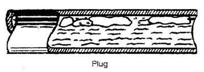
Two phase gas liquid flow is commonly occur in any oil & gas production and processing system. Several flow patterns can occur in two phase gas liquid flow. There are Bubble flow (with minimum vapor bubble), Plug flow, Stratified flow, Wavy flow, Slug flow, Annular flow and Mist/Dispersed flow (with minimum liquid droplet). See following images.


Obvious Location
Present of two phase gas liquid may be obvious and be easily identified during development phase. Typical example are Full-Well-Stream (FWS) production which possibly producing hydrocarbon in gas and liquid form. Formation water, condensed water, mercury, and injected chemical (e.g. corrosion inhibitor, hydrate inhibitor, etc) in liquid form, wax in slurry form and sand in solid form may also present in the FWS, which typically result complicated multiphase form. Partial stabilized condensate travel long distance experience high pressure drop lead to vaporization. Vapor travel long distance experience ambient and J-T (isenthalpic process) cooling lead to condensation. Hot saturated vapor is cooled by air cooler or heat exchanger results condensation, vapor or liquid passing through turbine experience isentropic process, etc. These streams are obvious and can be easily identified in process simulation. Generally example are :
Present of two phase gas liquid may be obvious and be easily identified during development phase. Typical example are Full-Well-Stream (FWS) production which possibly producing hydrocarbon in gas and liquid form. Formation water, condensed water, mercury, and injected chemical (e.g. corrosion inhibitor, hydrate inhibitor, etc) in liquid form, wax in slurry form and sand in solid form may also present in the FWS, which typically result complicated multiphase form. Partial stabilized condensate travel long distance experience high pressure drop lead to vaporization. Vapor travel long distance experience ambient and J-T (isenthalpic process) cooling lead to condensation. Hot saturated vapor is cooled by air cooler or heat exchanger results condensation, vapor or liquid passing through turbine experience isentropic process, etc. These streams are obvious and can be easily identified in process simulation. Generally example are :
- Full Well Stream (FWS)
- Partial stabilized condensate with long pipeline
- Saturated vapor with long pipeline
- Liquid stream from separator passing a level control valve
- Downstream of Air cooler / Heat exchanger
- Turbine outlet
- Hot fluid mix with cool fluid continuously
Recommended :
Subscribes to FREE Hydrocarbon Processing
Non-obvious Location
There are certain stream may be not so obvious and may not be easily identified in process simulation. Hot saturated vapor flow in long pipe experience heat loss to ambient and frictional loss, condensation begin and two phase flow (i.e. mist flow, annular flow). Cold saturated or partial subcooled liquid experience frictional loss due to fittings, piping, etc and ambient heating results vaporization and two phase flow (i.e. bubble flow, wavy flow, slugging flow). Hot stream mix with cold stream may results equilibrium change and lead to two phase. Typical area is flare collection system. Hydrocarbon in process vessel at pressure once it is drained to drain collection header may flash and lead to vaporization. Generally example are :
Subscribes to FREE Hydrocarbon Processing
Non-obvious Location There are certain stream may be not so obvious and may not be easily identified in process simulation. Hot saturated vapor flow in long pipe experience heat loss to ambient and frictional loss, condensation begin and two phase flow (i.e. mist flow, annular flow). Cold saturated or partial subcooled liquid experience frictional loss due to fittings, piping, etc and ambient heating results vaporization and two phase flow (i.e. bubble flow, wavy flow, slugging flow). Hot stream mix with cold stream may results equilibrium change and lead to two phase. Typical area is flare collection system. Hydrocarbon in process vessel at pressure once it is drained to drain collection header may flash and lead to vaporization. Generally example are :
- Saturated vapor within plant (condensation)
- Cooled or subcooled liquid within plant (vaporization)
- Flare collection
- Hydrocarbon drain collection
Problems
Two phase gas liquid flow can cause several destructive problems. There are :
- Impingement erosion
- Splashing erosion
- Cavitation erosion
- Flashing erosion
- Flow induced vibration
- Surge / hammer
- Noise
- Decrease process performance
- Phase separation
Two phase gas liquid flow can lead to impingement, cavitation & flashing erosion. Two phase gas liquid flowing fluid where heavy phase is accelerated with light phase and induced high momentum and shearing stress on surface. Slugging flow in vapor-liquid system with large slug hammering on surface induce high momentum with medium velocity and high mass flux. Mist flow with droplet accelerate at vapor velocity induce high momentum with high velocity and low mass flux. Both induce high shear stress on the surface and increase material removal rate.
Flow Induced Vibration
High velocity compressible fluid in pipe is moving in turbulence pattern. Turbulence flow will induced vibration on pipe. Once the flow induced vibration frequency meeting the natural frequency of pipe support, resonance occur can lead to severe movement of pipe support. Present of two phase gas liquid flow can generate different level of frequency and increase possibility of resonances.
Surge & Hammer
Two phase gas liquid slugging and high velocity gas moving liquid at similar speed, severe vibration can occur when liquid slug is knocking/splashing on the pipe wall, especially at bend and elbow. Hot steam mix with cold condensate at the collection header results sudden steam vapor collapse. The collapse vapor results sudden lower pressure will lead sudden replacement of surrounding condensate. Sudden movement of condensate can results significant movement of condensate as well as piping and pipe support. Under designed pipe support may fail due to severe vibration.
Quick opening of valve for incompressible, multiphase and gas/vapor will results sudden change in momentum (0 to +mv) and subsequently instantaneous peak force acting on the piping. This phenomena is commonly occurs in control valve (CV), Blowdown valve (BDV) and pressure relief device i.e. pressure relief valve (PRV) and rupture disc (RD). The instantaneous peak force acting on the piping may potentially lead to piping failure.
Noise
Above phenomenon such as Impingement, Splashing, Cavitation & Flashing Erosion, Flow Induced Vibration and Surge & Hammer may also generate noise which potentially exceeded the allowable noise limit.
Affect process performance
In oil and gas production, condensate-produced water bulk separation occur in slug catcher / inlet receiver follow by a Condensate separator. Some process design may include a filter coalescing separator to promote water droplet coalescing (using coalescing element) and separation before it is sent to Condensate stabilization. Condensate at saturation point from Condensate separator feeding to Filter Coalescing separator will experience frictional drop and potential lead to vaporization. Vapor will accumulate in the filter coalescing separator and seriously affect Coalescing activity in Filter Coalescing Separator.
Plate heat exchanger (PHE) is used in Solvent e.g. Amine, MEG, TEG, etc regeneration to recover heat from lean solvent stream and promote energy saving. Hydrocarbon and / or vapor bubble under carry from Solvent Absorber to PHE potentially accumulate in the PHE and seriously affect the heat transfer in PHE.
Phase Separation - Mal-Distribution
Air cooler used for fluid cooling is widely used in Oil & Gas and Petrochemical plant. Hot fluid is fed to a Inlet header box, distribute fluid into tubes (normally finned) where cooling take place and cooled fluid is collected in the Outlet header box. If hot two phase gas liquid fluid feeding to the inlet header box, liquid with higher momentum tends to flow preferential path (straight) compare to vapor with lower momentum. The lead to serious vapor-liquid mal-distribution. Fluid (vapor dominant) feed to tube closer to inlet possibly over cooled whilst fluid (liquid dominant) feed to tube further from inlet possibly under cooled. For large duty air cooling system, fluid may further distribute into multiple header boxes and multiple unit air cooler, this will further create mal-distribution of fluid.
Knowing the problems caused by two phase gas liquid flow, identification of potential two phase gas liquid becoming an important activity during design phase. Process engineer shall take extra care during design phase and provide necessary prevention measures to minimize / avoid occurrence of two phase flow.
Related Post
- Facts about Erosion & Erosion-Corrosion
- Erosion & Erosion - Corrosion
- Several Criteria and Constraints for Flare Network - Process
- Assess Potential Piping Failure Due to Valve Quick Opening with Two-Phase Vapor Liquid
- How Fluid Characteristic affect 2 phase Relief via PSV on Liquid filled Vessel Exposing to External Fire
Labels: Fluid Flow, hydrualic
Tuesday, February 9, 2010

FREE Chemical Engineering Digital Issue for Feb 2010...

Kettle Troubleshooting
Here’s proof that kettle reboilers can behave like thermosiphons and thereby bottleneck an entire plant. Understand the mechanism to blame and avoid it with these prevention and troubleshooting tips

Carbon dioxide, in its supercritical state, is being used to replace conventional organic solvents in chemical processes
Beyond Plant design
Simulation software finds use in plant optimization, energy reduction and operator training projects

Some pointers to help you find where energy savings can be located at your plant
FAYF - Positive Displacement Pumps
***********************
TIPSIf you are subscriber, you may access previous digital releases. Learn more in "How to Access Previous Chemical Engineering Digital Issue".
If you yet to be subscriber of Chemical Engineering, requested your FREE subscription via this link (click HERE). Prior to fill-up the form, read "Tips on Succession in FREE Subscription".
Related Post
Labels: E-Doc, Education, Learning
Sunday, February 7, 2010
In recent project, there was a topic being discussed. What are the measures can be considered to reduce the likelihood of pump cavitation ?. To answer to this question, we may need to understand some background about pump cavitation phenomenon. Previous posts as follow may probably provide some background information :
- What is pump cavitation ?
- How Pump Cavitation Sound and Looks Like ?
- Why Cavitation is Destructive ?
- Damages by Cavitation
- Relationship between NPSHa & NPSHr
Recommended :
Key to ensure no detrimental cavitation is the ensure NPSHa is higher than NPSHr. One may have to take extra note that pump cavitation can exist eventhough NPSHa is above the NPSHr of a centrifugal pump. However, it suction energy is sufficient low (below 3% head drop) and will not results cavitation which is detrimental to pump internal (discussed in "Facts About NPSH - Cavitation Even NPSHa More than NPSHr ?". Therefore, two main parameters we may have to focus are NPSHa and NPSHr.
Increase NPSHa
Previous post "How to Increase NPSHa to a Pump ?" , several points have been highlighted. Will further expand. Following equation define NPSHa :
where
Hp - pressure head
Hs - static head gain
Hf - frictional loss
Hv - velocity head
Hvp - vapor pressure head
NPSHa = Hp + Hs - Hf - Hv - Hvp
where
Hp - pressure head
Hs - static head gain
Hf - frictional loss
Hv - velocity head
Hvp - vapor pressure head
The key is to increase Hp and Hs whilst decrease Hf, Hv and Hvp
(1) Increase suction line size to reduce frictional loss (decrease Hf ) and velocity head (decrease Hv)
(2) Rearrange and /or redesign suction pipe work to minimise bends, valves and fittings to reduce frictional loss (decrease Hf )
(3) Reduce suction pipe length to reduce frictional loss (decrease Hf )
(4) Use smoother pipe (lower friction factor) to reduce frictional loss (decrease Hf ) e.g. SS instead of CS
(5) Raise suction vessel to increase static head (increase Hs )
(6) Lower pump elevation to increase static head (increase Hs)
(7) Increase pressure in suction vessel to increase suction pressure head (increase Hp) e.g. pressurize suction drum with inert gas
(8) Reduce fluid vapor pressure to decrease vapor pressure head (decrease Hvp) e.g. subcool fluid by dropping it temperature
Decrease NPSHr
Suction specific speed ( Nss) of a pump is a dimensionless number expressed as
Where
Nss : Suction Specific speed
Q : Flow rate (gpm) at the Best Efficiency Point
N : Pump rotational speed (rpm)
NPSHr : Net Positive Suction Head required (ft)
(9) Use low speed pump
Nss = ( N* Q 0.5 ) / (NPSHr)0.75
Where
Nss : Suction Specific speed
Q : Flow rate (gpm) at the Best Efficiency Point
N : Pump rotational speed (rpm)
NPSHr : Net Positive Suction Head required (ft)
(9) Use low speed pump
Decrease pump speed reduce NPSHr. Therefore use low speed pump required lower NPSHr.

(10) Use double suction impeller
Double suction impeller as shown in below image will reduce flow to each impeller by half and will reduce the NPSHr by approximately 36%-37%.

(11) Increase impeller eye area to minimize inlet pressure drop. The downside is introduction of suction recirculation. There shall be a balance in eye area selection.
(12) Use cavitation resistance material like SS (discussed in "Stainless Steel SS316 resist to CAVITATION ?"
(13) Use Suction Inducer to streamline suction flow to pump and reduce suction pressure drop
Process Treatment
Besides above measures, process engineer may also consider other process measures :
(14) Use of pump in series to reduce pump capacity of pump and reduce pump NPSHr
(15) Use of booster pump to provide sufficient head for main pump NPSHr
(16) Vortex in suction results vapor entrainment into liquid and lead to pump cavitation. Install vortex breaker at vessel outlet to avoid vapor entrainment (discussed in "Vortex Breaker to Avoid Vapor Entrainment") and;
(17) Ensure sufficient liquid height above vessel outlet to avoid vapor entrainment (discussed in "Estimate Minimum Submergence to Avoid Vapor Entrainment"
Above listed the ways to minimize likelihood of pump cavitation by increasing NPSHa, reducing NPSHr and introducing process treatment.
Related Post
Above listed the ways to minimize likelihood of pump cavitation by increasing NPSHa, reducing NPSHr and introducing process treatment.
Related Post
- Hydraulic...
- Pump
- Facts About NPSH - Cavitation Even NPSHa More than NPSHr ?
- Protect Pump for Longer Operation
- Basis & Tips on Setting Centrifugal Pump "Warming" Recycle Flow
- Flow-Delta P Protection Strategy
- Centrifugal Pump Minimum Flow Control Strategies
- Quick Check Pump Performance Using Motor Data and Field Measure Current
- Is PumpSmart Right Solution for You ?
- Vortex Breaker to Avoid Vapor Entrainment
Labels: Pump
Tuesday, February 2, 2010
Recommended :
- Subscribe FREE - Chemical Engineering
- Tips on Succession in FREE Subscription
Wet vapor potential condense and form liquid droplet (mist flow), vapor at high velocity will drag the droplet and flow approximately same speed as vapor. Whenever vapor with liquid droplet flow change in direction at elbow, bend, tee, valve, reducer, etc, liquid droplet will high density tends to impinge on the pipe wall and results erosion. Droplet impingement on pipe wall results erosion is commonly occur in Mist flow.
- Subscribe FREE - Chemical Engineering
- Tips on Succession in FREE Subscription
Wet vapor potential condense and form liquid droplet (mist flow), vapor at high velocity will drag the droplet and flow approximately same speed as vapor. Whenever vapor with liquid droplet flow change in direction at elbow, bend, tee, valve, reducer, etc, liquid droplet will high density tends to impinge on the pipe wall and results erosion. Droplet impingement on pipe wall results erosion is commonly occur in Mist flow.As liquid condensation increase, liquid droplet coalesce and accumulate and slowdown due to increase in mass and shearing force near wall. Vapor flows in swirling pattern in pipe creates centrifugal force pushing liquid stick to the pipe and moving forward. Swirling liquid moving forward at reasonable high velocity will results erosion on pipe wall and common occur in Annular flow.
Further increase in liquid flow will further slow down liquid movement in the pipe compare to vapor flow. Swirling flow and vapor dragging liquid surface tends to create liquid slug and restrict vapor in the pipe. Vapor at high velocity behind slug will accelerate slug and potentially hammering on pipe wall, elbow, bend, reducer,etc. Severe vibration, noise level and erosion will occurs in Slugging flow.
Mist flow, annular flow and slugging flow erode pipe in different ways and results different level of erosion. Many researchers and experts have spend their time and effort in deriving the erosion rate for two phase flow phenomenon and derive criteria in designing a pipe in two phase flow.
Droplet Erosion velocity threshold
As discussed in "Erosion & Erosion - Corrosion", erosivity is highly affected by particle/droplet velocity. High particle/droplet velocity results high momentum on impacting surface and leads to higher successive erosion. It is commonly understood that Erosion Rate (ER) is proportional to particle impacting Velocity raised to the power of n where n may range from 2 to 3 for ductile material (e.g. stainless steel) and possibly upto 6 for brittle material (e.g. some plastic material). Many researchers have conducted experiments and derived the Droplet Erosion velocity threshold for solid free fluid.
Droplet Erosion velocity threshold (VE ) for solid-free fluid
- DNV RP O501, VE = 70 ~ 80 m/s
- Salama & Venkatesh, VE = 26 ~ 118 m/s
- Shinogaya, VE = 80 m/s for Aluminum, 100 m/s for pure iron, 110 m/s for SS
- Svedeman & Arnold, VE = 30 m/s
Looking at above results, there is no one common range for the Droplet Erosion velocity threshold (VE ) for solid-free fluid due to complexity of two phase gas liquid flow.
Erosion model & Erosion Velocity Criteria
There are many models have been studied and proposed :
- API RP 14E Erosion model
- Salama & Venkatesh model
- Salama 2000 model
- DNV ERBEND model
- AEA Harwell model
- Tulsa SPPS model
Among all, API 14E erosion model is one of the earliest model being used in designing two phase gas liquid flow. Many others models have evolved from this basic model.
API RP 14E recommends
VE = C / Sqrt (mixture density)
VE in ft/s
mixture density in lb/ft3
C =100 for solid free corrosive and continuous operation service
C =125 for solid free corrosive and intermittent operation service
C =150 to 200 for solid free non-corrosive or CI controlled and continuous operation service
C =250 for solid free non-corrosive or CI controlled and intermittent operation service
Today, general perception is that API RP 14E recommendation is highly conservative. Many experiments have demonstrated this perception and recommends higher C value to be used.
Salama & Venkatesh have similar model and recommends :
C = 300 for solid free flow.
Salama recommends :
C = 400 for solid free non-corrosive fluid
C = 300 for solid free corrosive fluid
NORSOK standard P-001 (Ed. 5) recommends :
Wellhead flow-lines, production manifolds, process headers and other lines made of steel and transporting two-phase or multiphase flow, have a velocity limitation. When determining the maximum allowable velocity, factors such as piping geometry, well-stream composition, sand particle (or proppant) contamination and the material choice for the line shall be considered.
As a guideline, the maximum allowable velocity can be calculated by:
VE = C / Sqrt (mixture density)
where
VE in ft/s
mixture density in lb/ft3
C = 150
- Non corrosive service - For non corrosive well-stream and for corrosion resistant pipe materials the velocity should be limited to maximum 25 m/s if the well-stream includes only small amounts of sand or proppants (typical less than 30 mg sand/liter in the mixed flow).
- Corrosive service - For carbon steel (CS) piping systems the corrosion rate often limits the life time. With increased flow velocity the corrosion rate tend to increase due to increased shear forces and increased mass transfer. The flow velocity should be restricted to maximum 10 m/s to limit the erosion of the protective layer of corrosion products and reduce the risk for a corrosion inhibitor film break down.
Solid / Sand Present in Fluid
With the present of sand in single and/or two phase gas liquid flow further increase it complexity :
NORSOK standard P-001 (Ed. 5) recommends :
- Particle erosion in non corrosive service - For well-stream contaminated with particles the maximum allowable velocity shall be calculated based on sand concentration, piping geometry (bend radius, restrictions) pipe size and added erosion allowance. For the calculation of maximum velocity and life time specialised computer programmes are available and should be employed.
- Liquid flow with presents of sand, maximum allowable velocity (VMax ) are :
- 5 m/s for CS
- 7 m/s for SS/Titanium
NORSOK standard M-001, section 4.2.2.... recommends :
If sand production and/or particles from well cleaning and squeeze operations are expected, an erosion evaluation shall be carried out. The evaluation should be based on DNV RP-O-501
Salama recommends
where
VE = Erosion velocity limit (m/s)
D = pipe internal diameter (mm)
W = sand production rate (kg/day)
Mix den = Mixture density in (kg/m3)
Author has worked projects for many well-known oil and gas companies e.g. SHELL, EXXONMOBIL, TOTAL, BP, etc. All companies philosophy in erosion and erosion-corrosion and criteria in designing two phase gas liquid and sand-laden fluid are different.
Some Facts from Literature / Studies
Following are facts related to erosion : VE = D * Sqrt (mix den) / [20 * Sqrt (W)]
where
VE = Erosion velocity limit (m/s)
D = pipe internal diameter (mm)
W = sand production rate (kg/day)
Mix den = Mixture density in (kg/m3)
Author has worked projects for many well-known oil and gas companies e.g. SHELL, EXXONMOBIL, TOTAL, BP, etc. All companies philosophy in erosion and erosion-corrosion and criteria in designing two phase gas liquid and sand-laden fluid are different.
Some Facts from Literature / Studies
- Material such as tungsten carbides, coating, ceramic, etc commonly formed part of valve internal component are vulnerable to erosion.
- Particle impinging surface at varies angle results different erosion impact. Maximum impact is particle impacting perpendicular to surface
- Corrosion inhibitor (CI) form layer at internal pipe isolating / minimizing corrosive fluid contacts with corrosion susceptible material. Erosion due to fluid and particle impingement on CI layer potentially remove this protective layer. Commonly maximum velocity to avoid erosion of CI layer is 20 m/s. Some special CI can tolerate upto 50 m/s
- Sand production with downhole sand control, sand concentration at 1st receiver typically contains 1 to 50 ppmw of sand concentration. Past experience may reach 100 ppmw.
- A well produce 5 to 10 lb/day of sand is typically regarded as "Sand-free production".
- "Nominal solid-free" production is common defined as less than approx. 3 gram-per-m3 for liquid or less than 0.1 lb/mmscf for gas
- Well with downhold sand control may contains sand sizes typically range from 50 to 100 micron. Those without downhole sand control may range from 50 to 500 micron
- Erosion rate is commonly proportional to particle impact velocity into power of a factor range from 2 to 3 for steel.
- Higher fluid viscosity and density increase drag effect and "holding" capacity. Viscous and dense fluid tends to reduce particle impacting on surface
- Typical sand particle density is 2600 kg/m3
- API RP14E recommendation is conservative for solid free liquid service from erosion aspect. However, it potentially under-estimate solid free gas/vapor service (subject to droplet erosion)
- Rich amine potential expose erosion and cavitation effect when it is flashed from high pressure to lower pressure. Low threshold velocity should be used e.g. 1-2 m/s.
- Elbow and tee are most vulnerable to erosion compare to others component
- In gas and condensate production with present of solid / sand particle, API 14E has no clear recommendation to account for erosion rate.
Above is meant to provide some information for those engineers dealing in erosion. The complexity lead to many opinion and recommendation. What about yours in previous/present projects ???
Related Topics
- Erosion & Erosion - Corrosion
- Corrosion Resistance Material
- Material
- Pitting Corrosion - Mechanism & Prevention
- Crevice Corrosion Mechanism & Prevention
Labels: Corrosion, Corrosion Resistance Material, Erosion
