Saturday, March 27, 2010
Sulfide -stress cracking is basically a hydrogen-embrittlement phenomenon .Atomic hydrogen enters the steel to cause cracking. The hydrogen is generated on the surface of the steel because of a corrosion reaction. Iron reacts with h2s to form iron sulfide and hydrogen .This hydrogen is generated in atomic form on the steel surface ,where it can either combine to form molecular hydrogen and leave the surface as bubbles or diffuse into steel .This latter process may result in hydrogen embrittlement .Hydrogen sulfide prevents hydrogen recombination & thus promote entry of atomic hydrogen into steel .It is important to note that water must be present for this mechanism to occur ;without it SSC will not be observed ,because the ionization of the hydrogen sulfide is required.
Following is a lecture presentation on NACE Standard MR0175 - Petroleum and Natural Gas Industries – Materials for use in H2S-containing Environments in Oil and Gas Production.
Download
Related Post
- NACE MR0103 versus MR0175
- Common FAQs Related to NACE Standard MR0175 / ISO 15156
- Material Selection... USER Responsibility
- Error in NACE MR0175 / ISO 15156
- Guideline on Use of MR0175 / ISO15156
- What are the concerns related to H2S ?
- Safety Moment with H2S
- Pyrophoric Fire
- Pitting Corrosion - Mechanism & Prevention
Labels: Chloride Stress Corrosion Cracking, Corrosion, Corrosion Resistance Material, Material
Saturday, March 20, 2010
NACE MR0103 "Materials Resistant to Sulfide Stress Cracking in Corrosive Petroleum Refining Environments" was developed by Task Group 231 to provide a standard set of requirements for materials used in sour petroleum refinery equipment. In the past, NACE MR01752, "Sulfide Stress Cracking Resistant Metallic Materials for Oilfield Equipment", was frequently referenced for this equipment, even though refinery applications were outside the scope of MR0175. The process used to develop MR0103 is described, followed by a review of the requirements in the standard accompanied by highlights of the differences between MR0103 and the previous and current versions of MR0175.
An Overview of NACE International Standard MR0103 and Comparison with MR0175
Click here to download the article
A presentation has been prepared by the author which further summary the differences. You may download via the following link : Download Presentation Handout
Thanks to Don BUSH, Jeff BROWN & Keith LEWIS
Related Post
- Common FAQs Related to NACE Standard MR0175 / ISO 15156
- Material Selection... USER Responsibility
- Error in NACE MR0175 / ISO 15156
- Guideline on Use of MR0175 / ISO15156
- What are the concerns related to H2S ?
- Safety Moment with H2S
- Pyrophoric Fire
- Pitting Corrosion - Mechanism & Prevention
Labels: Chloride Stress Corrosion Cracking, Corrosion, Corrosion Resistance Material, Material
Tuesday, February 2, 2010
Recommended :
- Subscribe FREE - Chemical Engineering
- Tips on Succession in FREE Subscription
 Wet vapor potential condense and form liquid droplet (mist flow), vapor at high velocity will drag the droplet and flow approximately same speed as vapor. Whenever vapor with liquid droplet flow change in direction at elbow, bend, tee, valve, reducer, etc, liquid droplet will high density tends to impinge on the pipe wall and results erosion. Droplet impingement on pipe wall results erosion is commonly occur in Mist flow.
- Subscribe FREE - Chemical Engineering
- Tips on Succession in FREE Subscription
Wet vapor potential condense and form liquid droplet (mist flow), vapor at high velocity will drag the droplet and flow approximately same speed as vapor. Whenever vapor with liquid droplet flow change in direction at elbow, bend, tee, valve, reducer, etc, liquid droplet will high density tends to impinge on the pipe wall and results erosion. Droplet impingement on pipe wall results erosion is commonly occur in Mist flow.As liquid condensation increase, liquid droplet coalesce and accumulate and slowdown due to increase in mass and shearing force near wall. Vapor flows in swirling pattern in pipe creates centrifugal force pushing liquid stick to the pipe and moving forward. Swirling liquid moving forward at reasonable high velocity will results erosion on pipe wall and common occur in Annular flow.
Further increase in liquid flow will further slow down liquid movement in the pipe compare to vapor flow. Swirling flow and vapor dragging liquid surface tends to create liquid slug and restrict vapor in the pipe. Vapor at high velocity behind slug will accelerate slug and potentially hammering on pipe wall, elbow, bend, reducer,etc. Severe vibration, noise level and erosion will occurs in Slugging flow.
Mist flow, annular flow and slugging flow erode pipe in different ways and results different level of erosion. Many researchers and experts have spend their time and effort in deriving the erosion rate for two phase flow phenomenon and derive criteria in designing a pipe in two phase flow.
Droplet Erosion velocity threshold
As discussed in "Erosion & Erosion - Corrosion", erosivity is highly affected by particle/droplet velocity. High particle/droplet velocity results high momentum on impacting surface and leads to higher successive erosion. It is commonly understood that Erosion Rate (ER) is proportional to particle impacting Velocity raised to the power of n where n may range from 2 to 3 for ductile material (e.g. stainless steel) and possibly upto 6 for brittle material (e.g. some plastic material). Many researchers have conducted experiments and derived the Droplet Erosion velocity threshold for solid free fluid.
Droplet Erosion velocity threshold (VE ) for solid-free fluid
- DNV RP O501, VE = 70 ~ 80 m/s
- Salama & Venkatesh, VE = 26 ~ 118 m/s
- Shinogaya, VE = 80 m/s for Aluminum, 100 m/s for pure iron, 110 m/s for SS
- Svedeman & Arnold, VE = 30 m/s
Looking at above results, there is no one common range for the Droplet Erosion velocity threshold (VE ) for solid-free fluid due to complexity of two phase gas liquid flow.
Erosion model & Erosion Velocity Criteria
There are many models have been studied and proposed :
- API RP 14E Erosion model
- Salama & Venkatesh model
- Salama 2000 model
- DNV ERBEND model
- AEA Harwell model
- Tulsa SPPS model
Among all, API 14E erosion model is one of the earliest model being used in designing two phase gas liquid flow. Many others models have evolved from this basic model.
API RP 14E recommends
VE = C / Sqrt (mixture density)
VE in ft/s
mixture density in lb/ft3
C =100 for solid free corrosive and continuous operation service
C =125 for solid free corrosive and intermittent operation service
C =150 to 200 for solid free non-corrosive or CI controlled and continuous operation service
C =250 for solid free non-corrosive or CI controlled and intermittent operation service
Today, general perception is that API RP 14E recommendation is highly conservative. Many experiments have demonstrated this perception and recommends higher C value to be used.
Salama & Venkatesh have similar model and recommends :
C = 300 for solid free flow.
Salama recommends :
C = 400 for solid free non-corrosive fluid
C = 300 for solid free corrosive fluid
NORSOK standard P-001 (Ed. 5) recommends :
Wellhead flow-lines, production manifolds, process headers and other lines made of steel and transporting two-phase or multiphase flow, have a velocity limitation. When determining the maximum allowable velocity, factors such as piping geometry, well-stream composition, sand particle (or proppant) contamination and the material choice for the line shall be considered.
As a guideline, the maximum allowable velocity can be calculated by:
VE = C / Sqrt (mixture density)
where
VE in ft/s
mixture density in lb/ft3
C = 150
- Non corrosive service - For non corrosive well-stream and for corrosion resistant pipe materials the velocity should be limited to maximum 25 m/s if the well-stream includes only small amounts of sand or proppants (typical less than 30 mg sand/liter in the mixed flow).
- Corrosive service - For carbon steel (CS) piping systems the corrosion rate often limits the life time. With increased flow velocity the corrosion rate tend to increase due to increased shear forces and increased mass transfer. The flow velocity should be restricted to maximum 10 m/s to limit the erosion of the protective layer of corrosion products and reduce the risk for a corrosion inhibitor film break down.
Solid / Sand Present in Fluid
With the present of sand in single and/or two phase gas liquid flow further increase it complexity :
NORSOK standard P-001 (Ed. 5) recommends :
- Particle erosion in non corrosive service - For well-stream contaminated with particles the maximum allowable velocity shall be calculated based on sand concentration, piping geometry (bend radius, restrictions) pipe size and added erosion allowance. For the calculation of maximum velocity and life time specialised computer programmes are available and should be employed.
- Liquid flow with presents of sand, maximum allowable velocity (VMax ) are :
- 5 m/s for CS
- 7 m/s for SS/Titanium
NORSOK standard M-001, section 4.2.2.... recommends :
If sand production and/or particles from well cleaning and squeeze operations are expected, an erosion evaluation shall be carried out. The evaluation should be based on DNV RP-O-501
Salama recommends
where
VE = Erosion velocity limit (m/s)
D = pipe internal diameter (mm)
W = sand production rate (kg/day)
Mix den = Mixture density in (kg/m3)
Author has worked projects for many well-known oil and gas companies e.g. SHELL, EXXONMOBIL, TOTAL, BP, etc. All companies philosophy in erosion and erosion-corrosion and criteria in designing two phase gas liquid and sand-laden fluid are different.
Some Facts from Literature / Studies
Following are facts related to erosion : VE = D * Sqrt (mix den) / [20 * Sqrt (W)]
where
VE = Erosion velocity limit (m/s)
D = pipe internal diameter (mm)
W = sand production rate (kg/day)
Mix den = Mixture density in (kg/m3)
Author has worked projects for many well-known oil and gas companies e.g. SHELL, EXXONMOBIL, TOTAL, BP, etc. All companies philosophy in erosion and erosion-corrosion and criteria in designing two phase gas liquid and sand-laden fluid are different.
Some Facts from Literature / Studies
- Material such as tungsten carbides, coating, ceramic, etc commonly formed part of valve internal component are vulnerable to erosion.
- Particle impinging surface at varies angle results different erosion impact. Maximum impact is particle impacting perpendicular to surface
- Corrosion inhibitor (CI) form layer at internal pipe isolating / minimizing corrosive fluid contacts with corrosion susceptible material. Erosion due to fluid and particle impingement on CI layer potentially remove this protective layer. Commonly maximum velocity to avoid erosion of CI layer is 20 m/s. Some special CI can tolerate upto 50 m/s
- Sand production with downhole sand control, sand concentration at 1st receiver typically contains 1 to 50 ppmw of sand concentration. Past experience may reach 100 ppmw.
- A well produce 5 to 10 lb/day of sand is typically regarded as "Sand-free production".
- "Nominal solid-free" production is common defined as less than approx. 3 gram-per-m3 for liquid or less than 0.1 lb/mmscf for gas
- Well with downhold sand control may contains sand sizes typically range from 50 to 100 micron. Those without downhole sand control may range from 50 to 500 micron
- Erosion rate is commonly proportional to particle impact velocity into power of a factor range from 2 to 3 for steel.
- Higher fluid viscosity and density increase drag effect and "holding" capacity. Viscous and dense fluid tends to reduce particle impacting on surface
- Typical sand particle density is 2600 kg/m3
- API RP14E recommendation is conservative for solid free liquid service from erosion aspect. However, it potentially under-estimate solid free gas/vapor service (subject to droplet erosion)
- Rich amine potential expose erosion and cavitation effect when it is flashed from high pressure to lower pressure. Low threshold velocity should be used e.g. 1-2 m/s.
- Elbow and tee are most vulnerable to erosion compare to others component
- In gas and condensate production with present of solid / sand particle, API 14E has no clear recommendation to account for erosion rate.
Above is meant to provide some information for those engineers dealing in erosion. The complexity lead to many opinion and recommendation. What about yours in previous/present projects ???
Related Topics
- Erosion & Erosion - Corrosion
- Corrosion Resistance Material
- Material
- Pitting Corrosion - Mechanism & Prevention
- Crevice Corrosion Mechanism & Prevention
Labels: Corrosion, Corrosion Resistance Material, Erosion
Sunday, January 31, 2010
Recommended :
- Subscribe FREE - Chemical Engineering
- Tips on Succession in FREE Subscription
In oil and gas production system, sand is carried and produced together with oil / gas production. Sand produced cause erosion, erosion-corrosion, vibration, blockage, reduce productivity, sand separation and handling, additional maintenance, etc. Downhole sand control is introduced to minimize sand production. With downhole sand control, it will not absolutely sand free. There is still possibility of sand produced with oil/gas production. The produced sand size may range from 50 to 100 micron. However, the sand production quantity is sufficiently low and the impact and consequence are mild. This post will discuss some facts related to erosion.
- Subscribe FREE - Chemical Engineering
- Tips on Succession in FREE Subscription
In oil and gas production system, sand is carried and produced together with oil / gas production. Sand produced cause erosion, erosion-corrosion, vibration, blockage, reduce productivity, sand separation and handling, additional maintenance, etc. Downhole sand control is introduced to minimize sand production. With downhole sand control, it will not absolutely sand free. There is still possibility of sand produced with oil/gas production. The produced sand size may range from 50 to 100 micron. However, the sand production quantity is sufficiently low and the impact and consequence are mild. This post will discuss some facts related to erosion.Erosion is a material removal from a material surface with continuous particle, droplet and/or cavity impinging on the surface.Typical examples
- oil/gas production with sand particle
- gas / vapor with sand
- wet vapor with liquid droplet
- two phase flow with liquid mist/slug
- liquid cavitation with bubble collapse near/on the surface
- scale / corroded slag flowing in fluid impinging surface
- flashing and/or cavitation downstream of control valve
Erosion corrosion is an acceleration in corrosion attack in material with the present of erosion phenomenon. Corrosion inhibitor (CI) is used to minimize / mitigate corrosion in Corrosion susceptible material i.e. acidic wet fluid flowing in carbon steel, CI form an "isolation" layer on the carbon steel surface and to isolate corrosive fluid in contacts with corrosion susceptible material and to minimize corrosion activity on the surface. Present of erosion phenomenon will remove this CI layer (and material surface) and accelerate corrosion attack. For corrosion resistance alloy/material (CRA), a strong passivated material is formed at the CRA surface to protect it from further corrosion. Present of erosion phenomenon will remove the passivated layer and promote erosion-corrosion.
Erosion phenomenon
There are several possible erosion type and its phenomenon :
Erosion occurs in all particle/fluid reached components e.g.
(1) Fluid characteristic
Erosion phenomenon
There are several possible erosion type and its phenomenon :
- Fluid shear stress erosion - This typically occurs in any flowing fluid where fluid is moving on surface and induce shearing stress on the surface. Higher shearing force induce higher shearing force and lead to higher material removal rate
- Fluid impingement erosion (splashing & droplet impingement) - This typically occurs in multiphase flowing fluid where heavy phase is accelerated with light phase and induced high momentum and shearing stress on surface. Slugging flow in vapor-liquid system with large slug hammering surface induce high momentum with medium velocity and high mass flux. Mist flow with droplet accelerate at vapor velocity induce high momentum with high velocity and low mass flux. Both induce high shear stress on the surface and increase material removal rate
- Particle impingement erosion - Similar to droplet impingement on material surface, solid particle (e.g. sand, welded slag, corroded slag, solid scale, etc) is accelerated with vapor/gas. High velocity solid impinging on the material surface and remove material from its surface. Solid with high material hardness increase further material removal rate
- Fluid cavitation - Fluid with operating pressure above vapor pressure, flow through devices (e.g. control valve, restriction orifice, orifice plate, pump suction line, etc) results operating pressure drop below fluid vapor pressure where bubbles form and followed by pressure recovery (e.g. in control valve) and addition of external power (e.g. pump) lead to operating pressure again rise above fluid vapor pressure where bubbles collapse. This is commonly known as cavitation which results significant jet force acting on the surface and material removal from surface
- Fluid flashing - Similar to fluid cavitation, fluid with operating pressure above vapor pressure, flow through devices (e.g. control valve, restriction orifice, orifice plate, etc) results operating pressure drop below fluid vapor pressure where bubbles form and followed by pressure recovery (e.g. in control valve) lead to operating pressure again rise. In flashing case, recovered pressure is still below fluid vapor pressure, and bubbles permanently form downstream of these device. Increase bubbles formation lead to accelerate liquid, increase shearing force and material removal rate.
Erosion occurs in all particle/fluid reached components e.g.
- Chokes valve
- Elbow
- Blind tee
- Reducer & Constriction
- Partially close valve
- Check valve
- Non Full bore valve
- Branch
- Straight pipe
Erosion rate severeness subject to the way erosion occur. Direct impingement (perpendicular to impacting surface) of solid/fluid on material surface induce higher erosion rate compare to parallel shearing. High erosion occurs at Tee where solid / fluid impinge perpendicularly to pipe, elbow where solid / fluid impinge in multiple angles and choke valves with change in flow direction. High erosion rate also occurs in straight pipe with annular flow. Swirling vapor flow in annular flow pattern forcing liquid phase flowing along the pipe surface increases liquid shearing rate and frequency on the pipe surface.
Erosion can be affected by many factors which subject to (1) Fluid characteristic, (2) characteristic of impacting solid / particle / droplet and (3) properties of material being impacted. Factors Affecting Erosion
(1) Fluid characteristic
- Fluid velocity - Fluid carrying impacting solid / particle / droplet / slug flowing at higher velocity, high momentum is generated and lead to high impacting force and increase erosivity.
- Fluid viscosity - Fluid with high viscosity induce high dragging force on impacting solid / particle / droplet. Fluid with high viscosity has higher inertial in dragging impacting solid / particle / droplet to follow it flowing path and reduce tendencies and frequency impacting on the surface. Nevertheless, creation of eddies and flow path concentrated at particular location on the surface, will seriously promote erosion
- Fluid density - Similar high fluid viscosity, high fluid density has high capability in carrying and affecting flow path of impacting solid / particle / droplet.
- Flow pattern - Two phase flow with present of solid / particle, annular flow tends to push liquid and solid / particle concentrated at the pipe surface and increase erosivity. Slugging flow with severe slug impacting on the pipe surface would seriously increase erosivity and it is enhanced by present of solid / particle / sand
- Particle production level - High solid / particle / droplet present in fluid leads to higher impacting frequency and higher erosivity. Minimizing solid / particle / sand production e.g. efficient downhole sand control, etc and improve fluid dryness e.g. dew point, well operated separator, filter coalescing, etc are the ways to minimize erosion
- Particle velocity - Erosivity is highly affected by particle velocity. High particle velocity results high momentum on impacting surface and lead higher successive erosion. It is commonly understood that Erosion Rate (ER) is proportional to particle impacting Velocity raised to the power of n where n may range from 2 to 3 for ductile material (e.g. stainless steel) and possibly upto 6 for brittle material (e.g. some plastic material)
- Particle density - There are two major contributions by high particle density. (1) high particle density results high impacting momentum and successive erosion. (2) high particle density increase particle flowing inertial and reduce the tendencies of fluid carrying capability and drive away from impacting the surface
- Particle viscosity - Contrary to particle density, high particle viscosity increase fluid carrying and dragging effect and drive away from impacting surface
- Impacting angle - Impacting angle play a major rule in erosion. Direct impacting particle would results most severe erosion and reduce with impacting angle. Least erosion occurs when particle flowing parallel with impacting surface
- Particle shape - Sharp particle compare to round particle tends to increase erosivity
- Particle size - Very small particle tends to flow with flowing fluid and drag away from impacting surface. Very large particle tends to flow slower in the flowing fluid. Medium size particle results severe erosion as it flow at high velocity and momentum (less drive by flowing fluid) comparatively
- Particle hardness - Hard particle (e.g. stone) results higher erosion than soft particle (e.g. mud)
- Material hardness - Increase material hardness reduces erosivity
- Material ductility - Some material with high ductility tends to reduce erosivity. Robber or polymer type material tends to absorb impacting energy and reduces erosivity. Stainless steel with work-hardening property tends to increase its hardness once it is impacted.
- Material brittleness - Some material present high hardness but brittle. Erosion is so much affecting healthiness of the material but impacting momentum tends to increase material localise cracks (due to its brittleness property)
Related Topics
- Corrosion Resistance Material
- Material
- Pitting Corrosion - Mechanism & Prevention
- Crevice Corrosion Mechanism & Prevention
Tuesday, February 3, 2009
Display problem ? Click HERE
Recommended :

Steam is commonly used in oil & gas, refinery, petrochemical and power plant for heating and power generation. Steam is condensed in equipment for heating and in turbine for power generation. Condensate is then collected in common collector before it is sent to condensate drum. Condensate from drum is then pumped to Boiler for steam generation via a Boiler Feed Water (BFW) pump. BFW is normally a centrifugal type and a minimum flow recirculation line is provided on BFW discharge for pump protection.
Minimum flow control can be
- a flow meter on pump discharge with control valve on recycle line
- a flow-Delta P and flow meter on pump discharge with control valve on recycle
- an automatic Recirculation Valves (ARC) valve
 Problems
There are several problems assocaited with these valves in condensate recycle line :
i) Erosion - flashing and cavitation results trim and body erosion
ii) Severe noise and vibration - flashing and cavitation
iii) Leakage - energy loss
Recommendation
Several recommendations to miniminse above mentioned problems :
i) Harden trim to resist erosion cause by flashing and cavitation
ii) Correct material i.e. alloy selection to avoid erosion-corrosion
iii) Anti-cavitation trim to minimise / avoidance of cavitation.
iv) Multi-stage anti-cavitation trim for small valve
v) Multi-hole anti-cavitation trim for large valve
vi) Multi cage anti-cavitation trim for high pressure recovery (FL) valve
vii) High lift (more than 20% lift) valve to increase trim life
viii) Large body valve to minimise velocity (high velocity lead to high erosion) in the valve inlet and outlet chambers. [Tips : Body erosion proportional to 3-5 power of velocity]
ix) Elevate condensate drum to increase back pressure to the valve (if possible)
x) Provide restriction orifice downstream of control valve to increase back pressure. One shall take note at low flow, the pressure drop acrosss RO is negligible. Majority pressure drop (energy being "killed") still occurred at valve
xi) Tight shut off (class V) valve to avoid leakage and hence energy loss.
Related Topic
Labels: Control valve, Corrosion, Minimum flow, Steam
Friday, January 23, 2009
Display problem ? Click HERE

Recommended :Earlier post "Crevice Corrosion Mechanism & Prevention" has briefly discussed mechanism of crevice corrosion and its prevention. As discussed, one of the preventive measures is to select correct material to resist crevice corrosion. Stainless Steel (SS) is known to resist to general corrosion by forming a thin, protective oxide film on it external surface, SS still susceptible to localized corrosion i.e. Chloride stress corrosion cracking (CSCC), crevice corrosion, pitting corrosion, etc once this protective film is partly damage. Stainless steel once expose to water (present of Chloride) with temperature higher than 60 degC, CSCC is potentially occurred. On the other hand, temperature lower than 60 degC, crevice and pitting corrosion is potentially occurred.
There are different grade of Stainless Steel i.e. SS304, SS316, S31803, S32205, etc. How Chloride [Cl] concentration, Sulfate [SO4] concentration, pH level, temperature, oxygen level, etc affecting crevice corrosion for different Stainless Steel ?

The Crevice Corrosion Engineering Guide for Stainless Steels (CCEG) is a program available FREE to check type of Stainless Steel susceptible to crevice corrosion in water under particular conditions and impurities. The CCEG is a program with predictive mathematical model of crevice corrosion to assist with the selection of stainless steels for use in chloride and sulphate containing waters, including sea water. It was jointly developed by Nickel Development Institute (NiDI) and Sheffield Testing Laboratories Ltd.

Application Range
This program has been developed with the following application range :
- Fluid : Water
- Operating temperature : 5 - 85 degC
- Chloride [Cl] concentration : 1-30,000 ppm
- Sulphate [SO4] concentration : 0-10,000 ppm
- Total Dissolved Solids (TDS) concentration : 0 - 65000 ppm or mg/L
- * Can be calculated base on 1.65 [Cl] + [SO4]
- Alkalinity : 0 - 10000 mg/L (as concentration of CaCO3 in mg/L)
- Hardness : 0 - 20000 mg/L (as concentration of CaCO3 in mg/L)
- pH : 5 - 9
The program will check for following material :
- S30400
- S31600
- S31700
- S31803
- S32205
- N08904
- 6% Mo SS
Example
Let take a water with following parameters :
- Chloride (ppm) : 1000
- Sulphate (ppm) : 100
- Hardness (as CaCO3 mg/L) : 100
- Alkalinity (As CaCO3 mg/L) : 100
- TDS (mg/L) : 1798
- pH : 7
- Temp (C) : 25
- Oxygen level (ppm) : 7
Download : Click here to download the program (1.17 MB).
Source : Nickel Development Institute (NiDI)
Related Topics
Labels: Chloride Stress Corrosion Cracking, Corrosion, Corrosion Resistance Material
Saturday, January 17, 2009
Display problem ? Click HERE
Recommended :
- Subscribe FREE - Energy Biz
- Tips on Succession in FREE Subscription
 Crevice is location /area / space where normal fluid has less contact and access with it. Typical example of crevice are gaps between parts, space between gaskets and bolt, inside seals, inside cracks due to external impact or scratches, spaces filled with deposits, plastic paper lay on the metal plate, etc. In crevice, the environment is different than area expose to normal fluid. For example, gasket with bolt. Bolt surface expose to atmosphere is oxygen rich while wet air trapped between bolt and gasket is stagnant and with limited oxygen. Localized corrosion occur in the crevice is called crevice corrosion.
Crevice Corrosion Example
Following is an example of crevice corrosion at pipe support.

Crevice corrosion is pretty similar to pitting corrosion as discussed in "Pitting Corrosion - Mechanism & Prevention".

Mechanism
A metal surface with gasket at shown above will potentially experience crevice corrosion. Oxygen rich fluid enters crevice between gasket and metal surface.
- Genenal Oxidation Corroion
Normal corrosion (general oxidation corrosion) will occur through the metal surface outside and inside the crevice. As oxygen in trapped fluid consumed oxygen, environment within crevice is deoxygenated (low in oxygen level) increases the potential difference between crevice environment and oxygen rich environment.
Metal (E.g. FE) surface (expose to atmosphere) is oxygen rich will becomes the cathode whilst the metal surface in the crevice (gasket contacted area) is low in oxygen level will becomes anode. This form a complete circuit where metal at the crevice (FE) will be ionized to release electron (e) and form ion Ferum (FE2+), this electron will travel to the metal surface expose to atmosphere to react with Oxygen (O2) and water (H2O) to form ion hydroxides (OH-). Ion Ferum (FE2+) will react with ion hydroxides (OH-) to form Ferum Oxide (Fe2O3) which typically a brown rust.
- Increases Acidity in Crevice Environment
The ions FE2+ formed potentially hydrolyze water (H2O) in tapped fluid and produced positive ion (i.e. H+) and FE (corrosion product). The corrosion product will further block the movement of trapped fluid and increase the corrosion potential. The H+ will further increase the acidity of the trapped fluid and this severely increases corrosivity of trapped fluid.
- Other Corrosion i.e. CSCC
Production of ion positive (H+) will also attract negative ions i.e Chlorides, Sulfates, etc outside crevice travel into the trapped fluid in crevice, accumulation of these negative ions will potentially results Chloride and Sulfate associated corrosion such Chloride stress corrosion cracking (CSCC).
Preventive measures
There are several preventive measures to minimize crevice corrosion.
i) Avoid / minimize crevices during design stage i.e. keep junction points as wide open as possible.
ii) Avoid / Minimise crevices during fabrication i.e. smooth weld
iii) Avoid / minimize solution get into crevice i.e. greasing bolt / nut
iv) Use high resistance material (high PRE material)
v) Avoid / Minimise crevices during operation. Scale settled on metal surface will form "crevice" and trapped fluid. Routine cleaning to remove scale is one of the effective way to minimise crevices.
vi) Avoid/ Minimize objects i.e plastic bag put on metal surface.
vii) External coating
Related Topics
- Subscribe FREE - Energy Biz
- Tips on Succession in FREE Subscription
Crevice is location /area / space where normal fluid has less contact and access with it. Typical example of crevice are gaps between parts, space between gaskets and bolt, inside seals, inside cracks due to external impact or scratches, spaces filled with deposits, plastic paper lay on the metal plate, etc. In crevice, the environment is different than area expose to normal fluid. For example, gasket with bolt. Bolt surface expose to atmosphere is oxygen rich while wet air trapped between bolt and gasket is stagnant and with limited oxygen. Localized corrosion occur in the crevice is called crevice corrosion.Crevice Corrosion Example
Following is an example of crevice corrosion at pipe support.

Crevice corrosion is pretty similar to pitting corrosion as discussed in "Pitting Corrosion - Mechanism & Prevention".

Mechanism
A metal surface with gasket at shown above will potentially experience crevice corrosion. Oxygen rich fluid enters crevice between gasket and metal surface.
- Genenal Oxidation Corroion
Normal corrosion (general oxidation corrosion) will occur through the metal surface outside and inside the crevice. As oxygen in trapped fluid consumed oxygen, environment within crevice is deoxygenated (low in oxygen level) increases the potential difference between crevice environment and oxygen rich environment.
Metal (E.g. FE) surface (expose to atmosphere) is oxygen rich will becomes the cathode whilst the metal surface in the crevice (gasket contacted area) is low in oxygen level will becomes anode. This form a complete circuit where metal at the crevice (FE) will be ionized to release electron (e) and form ion Ferum (FE2+), this electron will travel to the metal surface expose to atmosphere to react with Oxygen (O2) and water (H2O) to form ion hydroxides (OH-). Ion Ferum (FE2+) will react with ion hydroxides (OH-) to form Ferum Oxide (Fe2O3) which typically a brown rust.

- Increases Acidity in Crevice Environment
The ions FE2+ formed potentially hydrolyze water (H2O) in tapped fluid and produced positive ion (i.e. H+) and FE (corrosion product). The corrosion product will further block the movement of trapped fluid and increase the corrosion potential. The H+ will further increase the acidity of the trapped fluid and this severely increases corrosivity of trapped fluid.
- Other Corrosion i.e. CSCC
Production of ion positive (H+) will also attract negative ions i.e Chlorides, Sulfates, etc outside crevice travel into the trapped fluid in crevice, accumulation of these negative ions will potentially results Chloride and Sulfate associated corrosion such Chloride stress corrosion cracking (CSCC).
Preventive measures
There are several preventive measures to minimize crevice corrosion.
i) Avoid / minimize crevices during design stage i.e. keep junction points as wide open as possible.
ii) Avoid / Minimise crevices during fabrication i.e. smooth weld
iii) Avoid / minimize solution get into crevice i.e. greasing bolt / nut
iv) Use high resistance material (high PRE material)
v) Avoid / Minimise crevices during operation. Scale settled on metal surface will form "crevice" and trapped fluid. Routine cleaning to remove scale is one of the effective way to minimise crevices.
vi) Avoid/ Minimize objects i.e plastic bag put on metal surface.
vii) External coating
Related Topics
Labels: Chloride Stress Corrosion Cracking, Corrosion, Corrosion Resistance Material
Sunday, January 11, 2009
Display problem ? Click HERE
Recommended :
- Subscribe FREE - Processing Magazine
- Tips on Succession in FREE Subscription
 Earlier posts "Quick Estimation of CO2 Corrosion Rate", "CO2 Corrosion Rate Estimation Using M-506 Model" and "CO2 Corrosion Using Freecorp Model", the DeWaard Milliam model, Norsok M-506 model and FREECORP models have been introduced. All these corrosion estimation models are available FREE for all. Corrosion allowance (CA) is provided in pipeline / piping to cater for required design life. Low corrosion rate (CR) will require low CA. For high CR, higher CA is provided. In many events, corrosion inhibitor (CI) is injected into corrosive in order to reduce CR. Although low CA with CI injection, CI would incur high operation cost. Thus, a life cycle cost (LCC) study will require to be conducted to determining he cost effective option in provision of normal material with CA plus CI or Corrosion Resistance Material (CRA).
- Subscribe FREE - Processing Magazine
- Tips on Succession in FREE Subscription
Earlier posts "Quick Estimation of CO2 Corrosion Rate", "CO2 Corrosion Rate Estimation Using M-506 Model" and "CO2 Corrosion Using Freecorp Model", the DeWaard Milliam model, Norsok M-506 model and FREECORP models have been introduced. All these corrosion estimation models are available FREE for all. Corrosion allowance (CA) is provided in pipeline / piping to cater for required design life. Low corrosion rate (CR) will require low CA. For high CR, higher CA is provided. In many events, corrosion inhibitor (CI) is injected into corrosive in order to reduce CR. Although low CA with CI injection, CI would incur high operation cost. Thus, a life cycle cost (LCC) study will require to be conducted to determining he cost effective option in provision of normal material with CA plus CI or Corrosion Resistance Material (CRA).For the CA plus CI injection option, one of the factor shall be taken into account in determining CA is the availability of corrosion inhibition. There are many events would lead to corrosion inhibition unavailable i.e. maintenance, nonscheduled trip, deficiency of inhibition, unexpected flow, etc. Following is a simple method in determining the CA by consideration of Availability.
where :
CA = Corrosion rate
t = Design life
ICR = Inhibited Corrosion Rate
UCR = Uninhibited Corrosion Rate
Example :
A pipeline is design for 25 years, the corrosion rate is about 3 mm/year. High corrosion allowance (25 x 3 = 75 mm) is required and this has lead to injection of Corrosion Inhibition (CI) to reduce the corrosion rate to 0.3 mm/year. It is expected the availability of corrosion inhibition facilties is about 90%. Calculate CA required with CI injection.
t = 25
ICR = 0.3 mm / year
UCR = 3 mm / year
Av = 90%
CA = t x [ICR x Av + UCR x (1 - Av)]
CA = 25 x [0.3 x 90% + 3.0 x (1-90%)]
CA = 14.25 mm
Required CA is 14.25 mm.
A simple Corrosion Allowance Calculator is ready for download.
Download Corrosion Allowance Calculator (Excel).
Related Post
CA = t x [ICR x Av + UCR x (1 - Av)]
where :
CA = Corrosion rate
t = Design life
ICR = Inhibited Corrosion Rate
UCR = Uninhibited Corrosion Rate
Example :
A pipeline is design for 25 years, the corrosion rate is about 3 mm/year. High corrosion allowance (25 x 3 = 75 mm) is required and this has lead to injection of Corrosion Inhibition (CI) to reduce the corrosion rate to 0.3 mm/year. It is expected the availability of corrosion inhibition facilties is about 90%. Calculate CA required with CI injection.
t = 25
ICR = 0.3 mm / year
UCR = 3 mm / year
Av = 90%
CA = t x [ICR x Av + UCR x (1 - Av)]
CA = 25 x [0.3 x 90% + 3.0 x (1-90%)]
CA = 14.25 mm
Required CA is 14.25 mm.
A simple Corrosion Allowance Calculator is ready for download.
Download Corrosion Allowance Calculator (Excel).
Related Post
Labels: CO2, Corrosion, Corrosion Resistance Material
Sunday, November 9, 2008
Display problem ? Click HERE
 In earlier posts "Quick Estimation of CO2 Corrosion Rate" and "CO2 Corrosion Rate Estimation Using M-506 Model", two simple model i.e the DeWaard Milliam model and Norsok M-506 model have been introduced. The DeWaard Milliam model is just a simple chart while the M-506 model has been programmed into a software and available FREE for download.
In this post, another CO2 corrosion rate estimation software FREECORP will be introduced. FREECORP has been released for use by the corrosion research community. It was developed by scientists and programmers at Corrosion Center using publicly available knowledge of oil pipeline corrosion and it is distributed under GPL (General Public License) for FREE use by researchers, practitioners, and students of corrosion phenomena.
"FREECORP V1.0 is a simple corrosion model, strongly rooted in theory, which has been developed exclusively based on public knowledge. Currently, this model is capable of predicting uniform corrosion of carbon steel at a single point in an environment containing carbon dioxide, acetic acid, oxygen, and/or hydrogen sulfide. Iron carbonate film formation, a key factor in carbon dioxide corrosion, is simulated using an empirical correlation to improve the accuracy of corrosion rate prediction. Contributions to corrosion of various corrosion species can be calculated, which enables the exploration of dominant corrosion mechanisms in the corrosion process. Furthermore, polarization curves for each individual electrochemical reaction, net cathodic and anodic reactions and polarization sweeps can be optionally displayed. In a case of hydrogen sulfide corrosion, film formation is calculated and concentration profile of H2S across mass transfer layers on steel surface is displayed."
Related Post
Labels: CO2, Corrosion, Material
Tuesday, October 28, 2008
Display problem ? Click HERE
Recommended :
Subscribes to FREE Hydrocarbon Processing

Carbon Dioxide (CO2) with the present of free water in oil and gas would lead to generation of Carbonic acid. This has been briefly discussed in "CO2 Corrosion in Oil & Gas - Part 1". In this post and "CO2 Corrosion in Oil & Gas - Part 2", there are several articles related to CO2 corrosion.
In earlier discussion in "Quick Estimation of CO2 Corrosion Rate", other than DeWaard and Milliams model, there are other CO2 corrosion models :
Subscribes to FREE Hydrocarbon Processing
Carbon Dioxide (CO2) with the present of free water in oil and gas would lead to generation of Carbonic acid. This has been briefly discussed in "CO2 Corrosion in Oil & Gas - Part 1". In this post and "CO2 Corrosion in Oil & Gas - Part 2", there are several articles related to CO2 corrosion.
In earlier discussion in "Quick Estimation of CO2 Corrosion Rate", other than DeWaard and Milliams model, there are other CO2 corrosion models :
- LIPUCOR model by TOTAL
- HYDROCORR model by SHELL
- CASSANDRA model by BP
- NORSOK M-506 model by NTSI
- KSC model
- IFE model
- etc
M-506 CO2 corrosion rate calculation model
This NORSOK standard, which is a recommended practice, contains
- a computer program for corrosion rate calculations
- a user manual for the computer program. A description of the calculation model, the algorithms and the conditions for the corrosion rate calculations are given. In additions, methods and algorithms for calculation of essential input parameters to the corrosion rate calculations are given.
Download Software
Related Post
- CO2 Corrosion in Oil & Gas - Part 1
- CO2 Corrosion in Oil & Gas - Part 2
- What are the concerns related to H2S ?
- Several Concerns in High CO2 Field Development
- How does Supercritical fluid looks like ?
- High Temperature Hydrogen Attack in metal & alloy
- Hydrogen Embrittlement TEST method
- Chlorride stress corrosion cracking and use of correct MOC for seawater
Sunday, October 26, 2008
Display problem ? Click HERE
Recommended :
Subscribe FREE - Metal Finishing

NACE Standard MR0175 / ISO 15156 - Petroleum and Natural Gas Industries – Materials for use in H2S-containing Environments in Oil and Gas Production was established to provides limits of H2S partial pressure for precautions against sulfide stress cracking (SSC) and guidance for the selection and specification of SSC-resistant materials.
Following are some commonly asked question related to this standard.
Subscribe FREE - Metal Finishing
NACE Standard MR0175 / ISO 15156 - Petroleum and Natural Gas Industries – Materials for use in H2S-containing Environments in Oil and Gas Production was established to provides limits of H2S partial pressure for precautions against sulfide stress cracking (SSC) and guidance for the selection and specification of SSC-resistant materials.
Following are some commonly asked question related to this standard.
- Why NACE MR0175 Called NACE MR0175/ISO 15156 ?
- What is latest error in NACE MR0175 / ISO 15156
- How to use of MR0175 / ISO15156
- How NACE Standards Applied in Farris Pressure Relief Valves ?
- How NACE MR0175-2003 Impact on API 6A Equipemnt and Customer ?
- How ISO 15156 maintenance activities Functions works ?
- How do I know which are the latest editions of the three parts of NACE MR0175/ISO 15156 ?
- Are NACE MR0175/ISO 15156 and ISO 15156 identical in their technical content ?
- Are you aware that the page numbering of NACE and ISO editions of the standard sometimes differ ?
- How do these documents relate to previous editions of NACE MR0175 ?
- How often will the parts of NACE MR0175/ISO 15156 be updated ?
- What happens when amendments are required in the intervening period ?
- What status does a Technical Corrigendum or a Technical Circular have ?
- Are Technical Corrigenda and Technical Circulars incorporated into a standard when it is revised ?
- What is the difference between a Technical Corrigendum and a Technical Circular ?
- Where can Technical Corrigenda and Technical Circulars be obtained ?
- Does the ISO 15156 Maintenance Panel provide a consultancy service concerning materials and their application in sour service ?
- Can the ISO 15156 Maintenance Panel provide advice on the use of alternative materials not listed in the standard ?
- Will the ISO 15156 maintenance Panel provide interpretations for earlier editions of NACE MR0175 ?
- How do I get my material certified to NACE ?
- Is it all right for my company to require compliance with the 2002 version of MR0175 ?
- What do we need to put on the certificate?
- Can you give me the name of someone on a particular committee that I can call to ask a question about a standard ?
- I need to speak with someone who can give me advice on my water treatment system, tell me the best way to apply cathodic protection to my pipeline, or answer another technical question.
- I have a certain opinion on cathodic protection, and my customer has a different opinion. What is NACE’s position on this ?
Related Post
- Material Selection... USER Responsibility
- Error in NACE MR0175 / ISO 15156
- Guideline on Use of MR0175 / ISO15156
- What are the concerns related to H2S ?
- Safety Moment with H2S
- Pyrophoric Fire
- Pitting Corrosion - Mechanism & Prevention
Labels: Corrosion, Material, SSCC
Saturday, October 25, 2008
Display problem ? Click HERE
Recommended :
Subscribe FREE - Metal Finishing
This is a brief history about how NACE MR0175 / ISO 15156 is established since 1950s. It begun after World War II with the establishment of Technical report 1A152 "Sour Oil Well Corrosion" and 1B159 "Well Completion & Corrosion Control of High Pressure Gas Wells" when the demand to gas increased. This followed by NACE 1B163 "Recommendations on Material for Sour Service" and NACE 1F166 "Sulfide Cracking-Resistance Metallic Material for Valves for Production and Pipeline Service" in 1960s. First published of MR 0175 in 1975 and TM0177 "Testing of Metals for Resistance to Sulfide Stress Cracking at Ambient Temperatures" in 1978 and followed by TM0284 "Evaluation of Pipeline Steels for Resistance to Stepwise Cracking" in 1990. MR0175 is then merged with some EFC reports i.e. EFC#16 & #17 and finally first published the NACE MR0175 / ISO 15156 in 2003/2004.
Subscribe FREE - Metal Finishing
This is a brief history about how NACE MR0175 / ISO 15156 is established since 1950s. It begun after World War II with the establishment of Technical report 1A152 "Sour Oil Well Corrosion" and 1B159 "Well Completion & Corrosion Control of High Pressure Gas Wells" when the demand to gas increased. This followed by NACE 1B163 "Recommendations on Material for Sour Service" and NACE 1F166 "Sulfide Cracking-Resistance Metallic Material for Valves for Production and Pipeline Service" in 1960s. First published of MR 0175 in 1975 and TM0177 "Testing of Metals for Resistance to Sulfide Stress Cracking at Ambient Temperatures" in 1978 and followed by TM0284 "Evaluation of Pipeline Steels for Resistance to Stepwise Cracking" in 1990. MR0175 is then merged with some EFC reports i.e. EFC#16 & #17 and finally first published the NACE MR0175 / ISO 15156 in 2003/2004.Critical Improvements
Several critical improvements in the NACE MR 0175 with the published of NACE MR0175 / ISO 15156 in 2003/2004 :
- Inclusion of Stepwise cracking (SWC), Stress Oriented Hydrogen-Induced Cracking (SOHIC), Soft-zone cracking (SZC), etc. Read more on these corrosion type in "What are the concerns related to H2S ?"
- USER who are specifying and/or operating the equipment has full responsibility to ensure a material is works satisfactory in the intended environment. USER is responsible for the material selection. On the other hand, MANUFACTURER is responsible for meeting the metallurgical requirements.
- For revamping/modification of existing facilities and the material was designed for previous revision of NACE MR0175, if USER has the opinion the fluid condition stayed as before, USER may keep the existing material.
- NACE MR0175 / ISO 15156 is solely a guide documents for a proper selection of material in H2S environment. This documents providing list of material resistant to H2S environment, however, the material is not immune to to H2S environment. It implies that improper design, selection, fabrication, etc. may still lead to these material susceptible to H2S environment.
From above statements, the use and implementation of NACE MR0175 / ISO 15156 in H2S environment is within the decision of USER. A metallurgist and material engineer with the assistance of process and chemical engineer within the USER group i.e. COMPANY, CONTRACTOR, and LICENSOR are playing a major role in defining and implementing this standard. DO NOT RELY ON MANUFACTURER & VENDOR !!!
Read more in "Changes to NACE Standard MR0175-2003"
Download
Related Post
Labels: Corrosion, Material, SSCC
Friday, October 24, 2008
Display problem ? Click HERE
Recommended :
Subscribe FREE - Metal Finishing
NACE Standard MR0175 / ISO 15156 - Petroleum and Natural Gas Industries – Materials for use in H2S-containing Environments in Oil and Gas Production was established to provides limits of H2S partial pressure for precautions against sulfide stress cracking (SSC) and guidance for the selection and specification of SSC-resistant materials.
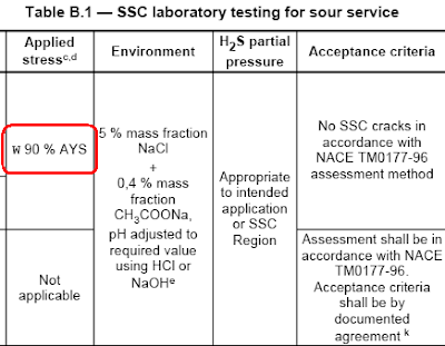
If you refer to NACE MR0175/ISO 15156-2, Table B.1 - SSC laboratory testing for sour service, column 3 "Applied Stress", you will find "w 90 % AYS". See following image.
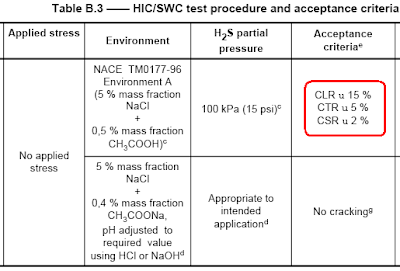
Now, refer to NACE MR0175/ISO 15156-2, Table B.3 - HIC/SWC test procedure and acceptance criteria, column 5 "Acceptance Criteria", you will find "CLR u 15 %", "CTR u 5 %" & "CSR u 2 %". See following image.
What is the meaning of
Download.
Related Post
Subscribe FREE - Metal Finishing
NACE Standard MR0175 / ISO 15156 - Petroleum and Natural Gas Industries – Materials for use in H2S-containing Environments in Oil and Gas Production was established to provides limits of H2S partial pressure for precautions against sulfide stress cracking (SSC) and guidance for the selection and specification of SSC-resistant materials.
If you refer to NACE MR0175/ISO 15156-2, Table B.1 - SSC laboratory testing for sour service, column 3 "Applied Stress", you will find "w 90 % AYS". See following image.
Now, refer to NACE MR0175/ISO 15156-2, Table B.3 - HIC/SWC test procedure and acceptance criteria, column 5 "Acceptance Criteria", you will find "CLR u 15 %", "CTR u 5 %" & "CSR u 2 %". See following image.
What is the meaning of
- "w 90 % AYS"
- "CLR u 15 %"
- "CTR u 5 %"
- "CSR u 2 %"
- "≥ 90 % AYS"
- "CLR ≤ 15 %"
- "CTR ≤ 5 %"
- "CSR ≤ 2 %"
- Table A.3 in NACE MR0175 / ISO 15156-2,
- Table, A.8, A.9, A.17, A.18, A.19...in NACE MR0175 / ISO 15156-3
Download.
Related Post
Wednesday, October 15, 2008
Display problem ? Click HERE
Carbon Dioxide (CO2) with the present of free water in oil and gas would lead to generation of Carbonic acid. This has been briefly discussed in "CO2 Corrosion in Oil & Gas - Part 1". In this post and "CO2 Corrosion in Oil & Gas - Part 2", there are several articles related to CO2 corrosion.
Since the initial studies by DeWaard and Milliams'(1975), there are many other follow-up studies on the CO2 corrosion phenomena. Many CO2 corrosion models have been proposed and used in predicting CO2 corrosion rate. They are :
DeWaard-Milliams nomograph
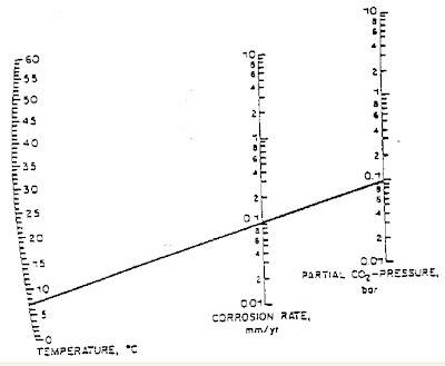
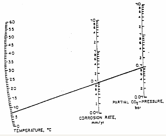
DeWaard and Milliams in their earlier studies has prepared a DeWaard-Milliams nomograph which is pretty simple and useful to have quick estimate for CO2 corrosion rate.
(Click to view larger image)
Since the initial studies by DeWaard and Milliams'(1975), there are many other follow-up studies on the CO2 corrosion phenomena. Many CO2 corrosion models have been proposed and used in predicting CO2 corrosion rate. They are :
- Dewaard- Milliam model
- LIPUCOR model by TOTAL
- HYDROCORR model by SHELL
- CASSANDRA model by BP
- NORSOK M-506 model by NTSI
- KSC model
- IFE model
- etc
DeWaard-Milliams nomograph
DeWaard and Milliams in their earlier studies has prepared a DeWaard-Milliams nomograph which is pretty simple and useful to have quick estimate for CO2 corrosion rate.
(Click to view larger image)
Above is an example where the fluid temperature is about 7 degC with CO2 partial pressure of 0.1 bar, the corrosion rate is 0.1 mm/year.
Related Post
Related Post
- CO2 Corrosion in Oil & Gas - Part 1
- CO2 Corrosion in Oil & Gas - Part 2
- What are the concerns related to H2S ?
- Several Concerns in High CO2 Field Development
- How does Supercritical fluid looks like ?
- High Temperature Hydrogen Attack in metal & alloy
- Hydrogen Embrittlement TEST method
- Chlorride stress corrosion cracking and use of correct MOC for seawater
Monday, October 13, 2008
Display problem ? Click HERE
Earlier post "What are the concerns related to H2S ?" has briefly discussed the concerns of Hydrogen Sulfide (H2S). There are mainly related to toxicity, flammability and corrosivity of H2S. Following are few video clips related to H2S. It provides some in depth understanding of H2S gas.H2S Properties & Characteristic
- H2S is a byproduct formed by decaying of organic matter
- It is toxic, explosive, flammable, corrosive
- Founded in Oil & gas, mining facilities, sewage, wastewater, land filled, etc
- Colorless gas
- Soluble in water
- Smell like rotten egg (sour gas)
- Burn H2S formed SO2, another toxic gas
- Can cause Sulfide Stress Corrosion Cracking (SSCC)
Accidents related to H2S
Truck driver almost killed by H2S
Hydrogen sulfide tanker crashes
Related Post
- What are the concerns related to H2S ?
- High Temperature Hydrogen Attack in metal & alloy
- Hydrogen Embrittlement TEST method
- Hydrogen present and it's impact to metallurgy
- Different Equation for Pitting Resistance Equivalent Number (PREN)
- Chlorride stress corrosion cracking and use of correct MOC for seawater
- Pitting Corrosion - Mechanism & Prevention
- How a Chloride Stress Corrosion Cracking Lookslike ?
Labels: Corrosion
