Sunday, January 31, 2010
Recommended :
- Subscribe FREE - Chemical Engineering
- Tips on Succession in FREE Subscription
 In oil and gas production system, sand is carried and produced together with oil / gas production. Sand produced cause erosion, erosion-corrosion, vibration, blockage, reduce productivity, sand separation and handling, additional maintenance, etc. Downhole sand control is introduced to minimize sand production. With downhole sand control, it will not absolutely sand free. There is still possibility of sand produced with oil/gas production. The produced sand size may range from 50 to 100 micron. However, the sand production quantity is sufficiently low and the impact and consequence are mild. This post will discuss some facts related to erosion.
- Subscribe FREE - Chemical Engineering
- Tips on Succession in FREE Subscription
In oil and gas production system, sand is carried and produced together with oil / gas production. Sand produced cause erosion, erosion-corrosion, vibration, blockage, reduce productivity, sand separation and handling, additional maintenance, etc. Downhole sand control is introduced to minimize sand production. With downhole sand control, it will not absolutely sand free. There is still possibility of sand produced with oil/gas production. The produced sand size may range from 50 to 100 micron. However, the sand production quantity is sufficiently low and the impact and consequence are mild. This post will discuss some facts related to erosion.Erosion is a material removal from a material surface with continuous particle, droplet and/or cavity impinging on the surface.Typical examples
- oil/gas production with sand particle
- gas / vapor with sand
- wet vapor with liquid droplet
- two phase flow with liquid mist/slug
- liquid cavitation with bubble collapse near/on the surface
- scale / corroded slag flowing in fluid impinging surface
- flashing and/or cavitation downstream of control valve
Erosion corrosion is an acceleration in corrosion attack in material with the present of erosion phenomenon. Corrosion inhibitor (CI) is used to minimize / mitigate corrosion in Corrosion susceptible material i.e. acidic wet fluid flowing in carbon steel, CI form an "isolation" layer on the carbon steel surface and to isolate corrosive fluid in contacts with corrosion susceptible material and to minimize corrosion activity on the surface. Present of erosion phenomenon will remove this CI layer (and material surface) and accelerate corrosion attack. For corrosion resistance alloy/material (CRA), a strong passivated material is formed at the CRA surface to protect it from further corrosion. Present of erosion phenomenon will remove the passivated layer and promote erosion-corrosion.
Erosion phenomenon
There are several possible erosion type and its phenomenon :
Erosion occurs in all particle/fluid reached components e.g.
(1) Fluid characteristic
Erosion phenomenon
There are several possible erosion type and its phenomenon :
- Fluid shear stress erosion - This typically occurs in any flowing fluid where fluid is moving on surface and induce shearing stress on the surface. Higher shearing force induce higher shearing force and lead to higher material removal rate
- Fluid impingement erosion (splashing & droplet impingement) - This typically occurs in multiphase flowing fluid where heavy phase is accelerated with light phase and induced high momentum and shearing stress on surface. Slugging flow in vapor-liquid system with large slug hammering surface induce high momentum with medium velocity and high mass flux. Mist flow with droplet accelerate at vapor velocity induce high momentum with high velocity and low mass flux. Both induce high shear stress on the surface and increase material removal rate
- Particle impingement erosion - Similar to droplet impingement on material surface, solid particle (e.g. sand, welded slag, corroded slag, solid scale, etc) is accelerated with vapor/gas. High velocity solid impinging on the material surface and remove material from its surface. Solid with high material hardness increase further material removal rate
- Fluid cavitation - Fluid with operating pressure above vapor pressure, flow through devices (e.g. control valve, restriction orifice, orifice plate, pump suction line, etc) results operating pressure drop below fluid vapor pressure where bubbles form and followed by pressure recovery (e.g. in control valve) and addition of external power (e.g. pump) lead to operating pressure again rise above fluid vapor pressure where bubbles collapse. This is commonly known as cavitation which results significant jet force acting on the surface and material removal from surface
- Fluid flashing - Similar to fluid cavitation, fluid with operating pressure above vapor pressure, flow through devices (e.g. control valve, restriction orifice, orifice plate, etc) results operating pressure drop below fluid vapor pressure where bubbles form and followed by pressure recovery (e.g. in control valve) lead to operating pressure again rise. In flashing case, recovered pressure is still below fluid vapor pressure, and bubbles permanently form downstream of these device. Increase bubbles formation lead to accelerate liquid, increase shearing force and material removal rate.
Erosion occurs in all particle/fluid reached components e.g.
- Chokes valve
- Elbow
- Blind tee
- Reducer & Constriction
- Partially close valve
- Check valve
- Non Full bore valve
- Branch
- Straight pipe
Erosion rate severeness subject to the way erosion occur. Direct impingement (perpendicular to impacting surface) of solid/fluid on material surface induce higher erosion rate compare to parallel shearing. High erosion occurs at Tee where solid / fluid impinge perpendicularly to pipe, elbow where solid / fluid impinge in multiple angles and choke valves with change in flow direction. High erosion rate also occurs in straight pipe with annular flow. Swirling vapor flow in annular flow pattern forcing liquid phase flowing along the pipe surface increases liquid shearing rate and frequency on the pipe surface.
Erosion can be affected by many factors which subject to (1) Fluid characteristic, (2) characteristic of impacting solid / particle / droplet and (3) properties of material being impacted. Factors Affecting Erosion
(1) Fluid characteristic
- Fluid velocity - Fluid carrying impacting solid / particle / droplet / slug flowing at higher velocity, high momentum is generated and lead to high impacting force and increase erosivity.
- Fluid viscosity - Fluid with high viscosity induce high dragging force on impacting solid / particle / droplet. Fluid with high viscosity has higher inertial in dragging impacting solid / particle / droplet to follow it flowing path and reduce tendencies and frequency impacting on the surface. Nevertheless, creation of eddies and flow path concentrated at particular location on the surface, will seriously promote erosion
- Fluid density - Similar high fluid viscosity, high fluid density has high capability in carrying and affecting flow path of impacting solid / particle / droplet.
- Flow pattern - Two phase flow with present of solid / particle, annular flow tends to push liquid and solid / particle concentrated at the pipe surface and increase erosivity. Slugging flow with severe slug impacting on the pipe surface would seriously increase erosivity and it is enhanced by present of solid / particle / sand
- Particle production level - High solid / particle / droplet present in fluid leads to higher impacting frequency and higher erosivity. Minimizing solid / particle / sand production e.g. efficient downhole sand control, etc and improve fluid dryness e.g. dew point, well operated separator, filter coalescing, etc are the ways to minimize erosion
- Particle velocity - Erosivity is highly affected by particle velocity. High particle velocity results high momentum on impacting surface and lead higher successive erosion. It is commonly understood that Erosion Rate (ER) is proportional to particle impacting Velocity raised to the power of n where n may range from 2 to 3 for ductile material (e.g. stainless steel) and possibly upto 6 for brittle material (e.g. some plastic material)
- Particle density - There are two major contributions by high particle density. (1) high particle density results high impacting momentum and successive erosion. (2) high particle density increase particle flowing inertial and reduce the tendencies of fluid carrying capability and drive away from impacting the surface
- Particle viscosity - Contrary to particle density, high particle viscosity increase fluid carrying and dragging effect and drive away from impacting surface
- Impacting angle - Impacting angle play a major rule in erosion. Direct impacting particle would results most severe erosion and reduce with impacting angle. Least erosion occurs when particle flowing parallel with impacting surface
- Particle shape - Sharp particle compare to round particle tends to increase erosivity
- Particle size - Very small particle tends to flow with flowing fluid and drag away from impacting surface. Very large particle tends to flow slower in the flowing fluid. Medium size particle results severe erosion as it flow at high velocity and momentum (less drive by flowing fluid) comparatively
- Particle hardness - Hard particle (e.g. stone) results higher erosion than soft particle (e.g. mud)
- Material hardness - Increase material hardness reduces erosivity
- Material ductility - Some material with high ductility tends to reduce erosivity. Robber or polymer type material tends to absorb impacting energy and reduces erosivity. Stainless steel with work-hardening property tends to increase its hardness once it is impacted.
- Material brittleness - Some material present high hardness but brittle. Erosion is so much affecting healthiness of the material but impacting momentum tends to increase material localise cracks (due to its brittleness property)
Related Topics
- Corrosion Resistance Material
- Material
- Pitting Corrosion - Mechanism & Prevention
- Crevice Corrosion Mechanism & Prevention
Saturday, January 23, 2010
Recommended :

Cavitation damage and fatigue due to acoustically induced vibration have discussed several times in previous posts such "cavitation" and "AIV". Control valve is known as one the common element / component in a plant potential source of cavitation and AIV related problems. Many efforts in combating both issues were proposed.
Typical solution is anti-cavitation trim e.g. staged trim, multi-flow path trim, labyrinth-disk type trim, etc.
i) Staged trim low noise
Staged trim low noise trim is adopted multi-stage pressure letdown similar to multi-stage RO.

ii) Multiple flow path type low noise trim
Multiple flow path low noise trim is one of the very effective noise (Sound Pwer Level) attenuator. It possibly reduce the noise level up to 40 dB. Image below shows a Multiple flow path low noise trim installed in a control valve.


Read more in "Fisher® WhisperFlo® Aerodynamic Noise Attenuation Trim".
iii) Labyrinth-disk type low noise trim
Another type of low noise trim is the Labyrinth-disk type low noise trim. It works approximate the same way as Multiple flow path type low noise trim.
Above trims design is commonly based on general principle in cavitation prevention which is ensure the operating pressure along the flow path in valve trim above fluid vapor pressure. See below image.

Below are some old useful articles related cavitation and multi-stage disc trim available for download. The post part of the continuation post from "Useful Documents Related to Control Valve"
 Fluid kinetic energy as a selection criteria for control valve
A selection criteria is provided that assures a control valve will perform its control function without the attendant problems of erosion, vibration, noise and short life. The criteria involves limits on the fluid kinetic energy exiting through the valve throttling area. Use of this criteria has resolved existing valve problems as demonstrated by retrofitting of the internals of many valves and vibration measurements before and after the retrofit. The selection criteria is to limit the valve throttling exit fluid kinetic energy to 70 psi (480 KPa) or less.
Multi-stage valve trim retrofits vibration eliminate damaging
Through the RHR valve trim retrofit at Quad Cities with multi-stage, tortuous-path, pressure reducing disks and an emergency capacity cage, the damaging vibration previously experience during system test operation has been eliminated. Further, an unlikely repetition of the previously experienced valve blockage by a Rad bag or any other medium has been precluded by the 50% over-capacity cage in the last 20% of valve stroke. Also, previous concerns regarding possible piping fatigue failures within the RHR system as a result of past severe vibration problems have been eliminated.
Specifying control valves for severe-service applications
Large number of the process control valves used in fossil-fired power plants must operate under severe-services conditions—that is, in high-pressure and / or high-temperature applications. When specifying valves for such applications, extreme care must be taken to avoid costly premature failures. This article discusses the stringent requirements that valves must meet to safety operate and deliver long-term performance under severe service conditions. Requirements are examined for both generic and specific applications.
Solving cavitation and Sand Erosion problems
In combating cavitation and erosion, principle in eliminating proposed are multistage velocity control and proper material of construction. Few valve applications in oil and gas production are more destructive and require more continuous maintenance than separator level-control valves. Over the years, the industry has frequently come to accept poor service life in this application. Service lives of a few weeks between complete rebuilds are common. But acceptance of poor service life is no longer necessary.
Control Valve Cavitation
Trim exit velocity is one of the parameter to be considered in control valve selection. Nevertheless, it may not completely explains entire physical phenomena occur in a control valve.The trim velocity approach may not reliable enough in solving problem related to control valve cavitation. The critical pressure drop method and the sigma method which will be introduced proves that the single stage valve may not experience cavitation, despite a trim exit velocity much higher than 100 ft/sec.
Impact of control valve design piping vibration
Vibration of the recycle piping system on the main oil export pumps from a platform in the North Sea raised concern about pipe breakage due to fatigue. Failures had already occurred in associated small bore piping and the instrument air supply lines. and control accessories on the recycle flow control valves. Concern also existed due to the vibration of non-flowing pipe work and systems such as the deck structure, cable trays and other instrumentation, which included fire and gas detection systems. The vibration was finally solved by changing the control valve to a trim that added enough pressure stages to assure the trim exit velocities and energy levels were reduced to levels demonstrated historically as needed in severe service applications. This vibration energy reduction was more than 16 times. This was achieved by reducing the trim exit velocity from peaks of 74 m/s to 12 m/s.
Special thanks to Control Component Inc.
Related Topic
- Problems and Measures for Condensate Recycle Control Valve
- FAQ Related to Control Valves
- Useful Documents Related to Control Valve
- FREE & Reliable Control Valve Sizing Software
- Anti-surge Control (ASC) or Capacity Control (CC) Valve in Vertical Upward Run ?
- Combine Anti-surge control (ASC) & Capacity Control (CC) Functions ?
Labels: AIV, Control valve, Noise
Wednesday, January 13, 2010

FREE Chemical Engineering Digital Issue for Jan 2010 already released !
Chemical Engineering Magazine as just released Jan 2010 issue. If you are the subscriber of Chemical Engineering, you should have received similar notification.
If you are subscriber, you may access previous digital releases. Learn more in "How to Access Previous Chemical Engineering Digital Issue".
If you yet to be subscriber of Chemical Engineering, requested your FREE subscription via this link (click HERE). Prior to fill-up the form, read "Tips on Succession in FREE Subscription".
Related Post
Chemical Engineering Magazine as just released Jan 2010 issue. If you are the subscriber of Chemical Engineering, you should have received similar notification.
***********************
Interesting articles for this month :Capital And Production Costs: Improving the Bottom Line
Decisions made in early phases of a project affect production costs for years to come. The disciplined method described here taps into potential savings
FAYF Low-Pressure Measurement
This one-page guide outlines techniques for measuring low pressures,or vacuum
Wastewater Treatment: Energy-Conservation Opportunities
Consider these options to improve energy efficiency and reduce the cost of treating wastewater
Pressure Relief Requirement During External Pool-Fire Contingency
A practical overview of the important factors that need to be considered when designing a pressure relief system
Updating the Rules For Pipe Sizing
The most economical velocity in piping continues to shift downward
A 'Sound' Solution to Material Flow Problems
Audiosonic acoustic cleaners use high-energy, low-frequency sound waves to eliminate particulate buildup, without damaging equipment
***********************
TIPSIf you are subscriber, you may access previous digital releases. Learn more in "How to Access Previous Chemical Engineering Digital Issue".
If you yet to be subscriber of Chemical Engineering, requested your FREE subscription via this link (click HERE). Prior to fill-up the form, read "Tips on Succession in FREE Subscription".
Related Post
Labels: E-Doc, Education, Learning
Thursday, January 7, 2010
Recommended :
- Subscribe FREE - Chemical Engineering
- Tips on Succession in FREE Subscription
Earlier post "Assess Potential Piping Failure Due to CV, BDV & PRV Quick Opening with Vapor Discharge" discussed about severe vibration and peak force act on the piping due to quick opening of valve. An assessment method to assess the potential failure of piping due to quick opening of valve has been presented. The equation in determining peak for is mainly for dry gas and/or vapor. This post will focus on two phase vapor liquid at the outlet of valve.
- Subscribe FREE - Chemical Engineering
- Tips on Succession in FREE Subscription
Earlier post "Assess Potential Piping Failure Due to CV, BDV & PRV Quick Opening with Vapor Discharge" discussed about severe vibration and peak force act on the piping due to quick opening of valve. An assessment method to assess the potential failure of piping due to quick opening of valve has been presented. The equation in determining peak for is mainly for dry gas and/or vapor. This post will focus on two phase vapor liquid at the outlet of valve.Peak force induced by sudden two-phase vapor liquid release
When a valve quick open from FULL Close to FULL Open, instantaneously release two-phase vapor liquid at downstream piping results peak force (FMax, kN) considering two-phase vapor liquid is in homogenous flow or frozen flow with no-slip.

where
W = Vapor mass flow (kg/s)
Di = Pipe internal diameter (m)
x = Vapor mass fraction
ρV = Vapor density (kg/m
ρL = Liquid density (kg/m
Piping Limiting Force
A steel piping with Piping limiting force (FLimit, kN),

with piping wall thickness correction factor,

Do = Pipe external diameter (m)
Di = Pipe internal diameter (m)
Wt = Pipe wall thickness (mm)
WtSch_40 = Schedule 40 pipe wall thickness (mm)
C = Pipe support correction factor
Pipe support stiffness level and correction factor
Pipe support stiffness level and correction factor subjects to support span length (LS) and pipe external diameter (Do) which can be determined from below chart.

Read more in "Quick Determination Pipe Support Stiffness Level and Correction Factor" for equations for differentiating support type.
Assessment Criteria
To ensure piping will not failed on sudden opening of valve, the following shall be met :
FMax < 0.3 FLimit
In the event FMax is more than 0.3 but less than 0.5 of FLimit, a detail small bore connection checking shall be conducted.
Ref :
1. "Guideline for avoidance of vibration induced fatigue in process work"
Ref :
1. "Guideline for avoidance of vibration induced fatigue in process work"
Related Post
- Assess Potential Piping Failure Due to CV, BDV & PRV Quick Opening with Vapor Discharge
- Quick Determination Pipe Support Stiffness Level and Correction Factor
- Check Valve Types and Selection
- Anti-surge Control (ASC) or Capacity Control (CC) Valve in Vertical Upward Run ?
- Combine Anti-surge control (ASC) & Capacity Control (CC) Functions ?
- Potential Problem associate with Double NRV in Series within a Line
- Several Strategies To Minimize Relief Capacity in Back-Flow Scenario
Labels: Piping, Surge, Vibration
Sunday, January 3, 2010
Recommended :
- Subscribe FREE - Chemical Engineering
- Tips on Succession in FREE Subscription

Earlier post "Assess Potential Piping Failure Due to CV, BDV & PRV Quick Openning with Vapor Discharge" presented a way to assessthe potential failure of piping due to quick opening of valve. The method required determination of pipe support stiffness level and correspondent correction factor (C) graphically. The post will shows mathematical equations of determining the stiffness level and correction factor. An spreadsheet has also been developed to ease checking and future works.
- Subscribe FREE - Chemical Engineering
- Tips on Succession in FREE Subscription
Earlier post "Assess Potential Piping Failure Due to CV, BDV & PRV Quick Openning with Vapor Discharge" presented a way to assessthe potential failure of piping due to quick opening of valve. The method required determination of pipe support stiffness level and correspondent correction factor (C) graphically. The post will shows mathematical equations of determining the stiffness level and correction factor. An spreadsheet has also been developed to ease checking and future works.
Pipe support stiffness level and correction factor
Pipe support stiffness level and correction factor subjects to support span length (LS) and pipe external diameter (Do) which can be determined from below chart.

Equation to differentiate Stiff and Medium Stiff support (blue line in above graph) is :
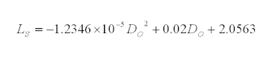
Equation to differentiate Stiff Medium and Medium support (pink line in above graph) is :

Equation to differentiate Medium and Flexible support (yellow line in above graph) is :

The correspondent correction factor (C) for support stiffness level are as follow :
Download
Ref :
1. "Guideline for avoidance of vibration induced fatigue in process work"

Equation to differentiate Stiff Medium and Medium support (pink line in above graph) is :

Equation to differentiate Medium and Flexible support (yellow line in above graph) is :

The correspondent correction factor (C) for support stiffness level are as follow :
- Stiff support ==> C = 4
- Medium Stiff support ==> C =2
- Medium support ==> C =1
- Flexible support ==> C =0.5
Download
Ref :
1. "Guideline for avoidance of vibration induced fatigue in process work"
Related Post
- Assess Potential Piping Failure Due to CV, BDV & PRV Quick Openning with Vapor Discharge
- Assess Potential Piping Failure Due to Valve Quick Opening with Two-Phase Vapor Liquid
- Check Valve Types and Selection
- Anti-surge Control (ASC) or Capacity Control (CC) Valve in Vertical Upward Run ?
- Combine Anti-surge control (ASC) & Capacity Control (CC) Functions ?
- Potential Problem associate with Double NRV in Series within a Line
- Several Strategies To Minimize Relief Capacity in Back-Flow Scenario
Saturday, January 2, 2010
 Simple update to IEM Members or those who are practicing Engineering in MALAYSIA...
Construction Quality Program supports the overall Project Quality Management during the construction phase of oil and gas projects. Construction Quality Program is an enhancement on the conventional Site Construction Quality Plan by implementing Project Turnover Work Process until Commissioning and Start-Up-Phase.
Among others, the talk will cover the following aspects : -
- Using Site Quality Plan to execute the project construction activities
- Enhancing Site Quality Plan by exploring best practice quality program
- Adopting Interface Quality Management among key project team members such as engineering, procurement, construction, commissioning and operation
- Maintaining consistent monitoring and verification activities to ensure that commissioning work commences only after construction activities and mechanical completion integrity checking have been completed
Construction Quality Program is Implemented throughout the construction phase by focusing on critical construction programs such as Piping Hydrotest Quality Program, Mechanical Completion Quality Program, Punchlist Quality Management, etc. Sharing of construction quality during construction phase will result in lesions learnt and best practices in the industry.
A talk on "Construction Quality Program in Oil & Gas Industry", organized by Oil, Gas and Mining Technical Division, IEM has been scheduled.
DATE : 9 JANUARY 2010 (Saturday)
TIME : 9.30 am TO 11.30 am ( Refreshment will be served at 9.00 am.)
VENUE : 2nd Floor, Wisma IEM, PETALING JAYA
CPD : 2 hours
SPEAKER : IR. ROSLIN BIN RAMLI
TIME : 9.30 am TO 11.30 am ( Refreshment will be served at 9.00 am.)
VENUE : 2nd Floor, Wisma IEM, PETALING JAYA
CPD : 2 hours
SPEAKER : IR. ROSLIN BIN RAMLI
Friday, January 1, 2010
Recommended :
- Subscribe FREE - Chemical Engineering
- Tips on Succession in FREE Subscription
Quick closure of valve will results sudden reversal of forward fluid flow and change in velocity. This action will subsequently results sudden momentum changes and lead to severe vibration and peak force act on the piping. In incompressible (liquid) and multiphase (two phase) fluid, it is similar to an accelerate "liquid column" hammering at a wall. The phenomena is commonly known as "water hammer". Water hammer is unlikely to occur in gas / vapor during quick valve closure due to compressible characteristic.

Quick closure of valve results sudden change in fluid momentum (+mv to -mv) would lead to instantaneous peak force. Similarly, quick opening of valve for incompressible, multiphase and gas/vapor will results sudden change in momentum (0 to +mv) and subsequently instantaneous peak force acting on the piping. This phenomena is commonly occurs in control valve (CV), Blowdown valve (BDV) and pressure relief device i.e. pressure relief valve (PRV) and rupture disc (RD). The instantaneous peak force acting on the piping may potentially lead to piping failure. An assessment method will be presented below to assess the potential failure of piping due to quick opening of valve.
This post will particularly focus on PRV, RD and BDV with gas/ vapor discharge only.
Peak force induced by sudden gas/vapor release
When a valve quick open from FULL Close to FULL Open, instantaneously release gas/vapor from valve upstream piping to downstream piping at choking velocity results peak force (FMax, kN) as :

W = Vapor mass flow (kg/s)
k = Vapor specific heat ratio
Mw = Vapor molecular weight
T = Temperature (K)
Piping Limiting Force
A steel piping with Piping limiting force (FLimit, kN),
with piping wall thickness correction factor,
Do = Pipe external diameter (m)
Di = Pipe internal diameter (m)
Wt = Pipe wall thickness (mm)
WtSch_40 = Schedule 40 pipe wall thickness (mm)
C = Pipe support correction factor
Pipe support stiffness level and correction factor
Pipe support stiffness level and correction factor subjects to support span length (LS) and pipe external diameter (Do) which can be determined from below chart.
Assessment Criteria
To ensure piping will not failed on sudden opening of valve, the following shall be met :
FMax < 0.3 FLimit
In the event FMax is more than 0.3 but less than 0.5 of FLimit, a detail small bore connection checking shall be conducted.
Ref :
1. "Guideline for avoidance of vibration induced fatigue in process work"
Ref :
1. "Guideline for avoidance of vibration induced fatigue in process work"
Related Post
- Assess Potential Piping Failure Due to Valve Quick Opening with Two-Phase Vapor Liquid
- Quick Determination Pipe Support Stiffness Level and Correction Factor
- Check Valve Types and Selection
- Anti-surge Control (ASC) or Capacity Control (CC) Valve in Vertical Upward Run ?
- Combine Anti-surge control (ASC) & Capacity Control (CC) Functions ?
- Potential Problem associate with Double NRV in Series within a Line
- Several Strategies To Minimize Relief Capacity in Back-Flow Scenario

Wish you and your family a happy and prosperous year in 2010...
