Tuesday, September 22, 2009
Display problem ? Click HERE
Recommended :
- Subscribe FREE - Chemical Engineering
- Tips on Succession in FREE Subscription
 Mixing of liquid in vapor using spraying nozzle is commonly used in reactor, column, mixing tank, etc. Mixing efficiency and effectiveness subject to liquid droplet size and contact time between droplet and vapor. In order to promote mixing efficiency and effectiveness, spraying nozzle is used to create small droplet size, well distribution of droplet and better spraying angle. Spraying liquid can be done hydraulically (high pressure liquid acting on a special design nozzle), gas assisted (gas kinetic energy acting on liquid for break-up) and rotary spraying (hydraulic pressure acting on moving device and results breakage of liquid).
- Subscribe FREE - Chemical Engineering
- Tips on Succession in FREE Subscription
Mixing of liquid in vapor using spraying nozzle is commonly used in reactor, column, mixing tank, etc. Mixing efficiency and effectiveness subject to liquid droplet size and contact time between droplet and vapor. In order to promote mixing efficiency and effectiveness, spraying nozzle is used to create small droplet size, well distribution of droplet and better spraying angle. Spraying liquid can be done hydraulically (high pressure liquid acting on a special design nozzle), gas assisted (gas kinetic energy acting on liquid for break-up) and rotary spraying (hydraulic pressure acting on moving device and results breakage of liquid).There are several well known spraying nozzle manufacturer such as BETE fog nozzle, Spraying Systems Co., etc Out of all, BETE Fog Nozzle, Inc., a leading supplier of engineered spray nozzle solutions, has posted high-resolution spray videos on their Web site to share with the public. BETE has published video in Youtube so that it can be viewed in public. Besides, BETE also provide embedding code so that publisher can display them in their website. Thanks to BETE.
The spray nozzle videos were created to help customers visualize the performance characteristics of the most common nozzle spray pattern types. The spray nozzle videos will assist customers in selecting nozzles for their application design and process improvements right from their own offices.
The spray nozzle videos were created to help customers visualize the performance characteristics of the most common nozzle spray pattern types. The spray nozzle videos will assist customers in selecting nozzles for their application design and process improvements right from their own offices.
Spray pattern videos now available include examples of the following nozzles:
- Spiral
- Axial Whirl
- Tangential Whirl
- Fan
- Misting
- Air Atomizing
- Tank Washing
This useful tool is the newest component of BETE Fog Nozzle, Inc.'s efforts to provide customers with solutions specially tailored to their unique spray challenges. BETE Fog Nozzle, utilizing our engineering resources and state-of-the-art Spray Laboratory, is fully prepared to collaborate with customers to supply nozzles that meet their most demanding industrial process conditions.
Following are 5 typical spraying videos.
Misting Spray Nozzle
Tangential Whirl, Hollow Cone Spray Nozzle
Full Cone Spiral Spray Nozzle
Extra-wide Full Cone Spiral Spray Nozzle
Air Atomizing, pressure-fed, internal mix, narrow angle, low flow
Related Post
- Pump Pressure Versus Head
- Why Centrifugal pump NPSH required increases with flow ?
- Tips for Centrifugal Pump
- Rule-of-thumb For Minimum Flow Recycle
- Basis & Tips on Setting Centrifugal Pump "Warming" Recycle Flow
- Potential Problem associate with Double NRV in Series within a Line
Friday, September 18, 2009
Display problem ? Click HERE
Recommended :
- Subscribe FREE - Chemical Engineering
- Tips on Succession in FREE Subscription
A pump with capacity of 100 m3/h and pump head of 75 m, base on suction drum elevation, fluid condition and suction piping condition, the calculated available Net Positive Suction Head (NPSHa) is 2m. This NPSHa shall be verified with NPSH required (NPSHr) by selected pump.
- Subscribe FREE - Chemical Engineering
- Tips on Succession in FREE Subscription
A pump with capacity of 100 m3/h and pump head of 75 m, base on suction drum elevation, fluid condition and suction piping condition, the calculated available Net Positive Suction Head (NPSHa) is 2m. This NPSHa shall be verified with NPSH required (NPSHr) by selected pump.How would you know if NPSHa is sufficient before the pump vendor provide the information on pump required Net Positive Suction Head (NPSHr) ?
Thoma Cavitation curve has been used to check as discussed in "Quick Check if NPSHa is Sufficient Using Thoma Cavitation Curve". Present post will discuss the usage of Suction Specific Speed for checking.
Suction specific speed ( Nss) of a pump is a dimensionless number expressed as
Suction specific speed ( Nss) of a pump is a dimensionless number expressed as
Nss = ( N* Q 0.5 ) / (NPSHr)0.75
Where
Nss : Suction Specific speed
Q : Flow rate (gpm) at the Best Efficiency Point
N : Pump rotational speed (rpm) *
NPSHr : Net Positive Suction Head required (ft)
Normal pump speed is 1450 rpm for low speed pump and 2950 rpm for high speed pump.
Soluation
Assumed pump curve is selected where pump flowrate is at best efficiency point
Pump Flow rate
Q = 100 m3/h
Q = 100 m3/h x ( 264.17 Gallon / m3 ) x (1 h / 60 min)
Q = 440.28 gpm
Pump Speed
Same as previous post, N = 2950 rpm for high speed pump
Pump Suction Specific Speed (Nss)
Same as previous post, Nss = 11000 is selected.
From above equation
Nss = ( N* Q 0.5 ) / (NPSHr)0.75
(NPSHr)0.75 = ( N* Q 0.5 ) / Nss
NPSHr = [( N* Q 0.5 ) / Nss](1/0.75)
NPSHr = [( 2950* 440.28 0.5 ) / 11000](1/0.75)
NPSHr = 10.009 ft = 3.05 m
Calculated NPSHr if 3.05 m is very close to NPSHr of 3.0 m as estimated using Thoma Curve. NPSHa of 2m is lower than NPSHr of 3.05m. Obviously the pump potential cavitate under normal operation as NPSHa less than NPSHr. Quick action to rectify the drum elevation & pump suction piping design may required to avoid potential future change.
Related Topic
- Facts About NPSH - Cavitation Even NPSHa More than NPSHr ?
- Protect Pump for Longer Operation
- Basis & Tips on Setting Centrifugal Pump "Warming" Recycle Flow
- Flow-Delta P Protection Strategy
- Centrifugal Pump Minimum Flow Control Strategies
- Quick Check Pump Performance Using Motor Data and Field Measure Current
- Is PumpSmart Right Solution for You ?
- Vortex Breaker to Avoid Vapor Entrainment
Labels: Pump
Monday, September 14, 2009
Display problem ? Click HERE
Recommended :
Subscribe FREE - Plant Services (USA only)
 Rupture disc (RD) is one of the non-reclosable type pressure relief device for vessel overpressure protection. It has been used in many application due to it uniqueness and special characteristic as covered in "Why Rupture (RD) Upstream of Pressure Relief Valve (PRV) ?". In some application, two RDs are placed in series to minimize inventory lost cause by premature opening of RD. Premature opening of RD may be cause by RD quality during manufacturing. Besides, premature opening of RD may be caused by wrong handling and installation of RDs.

Elfab, a RD manufacturer offer a few RD installation videos which could very useful for most operator. you may download from the following links or visit Elfab.
Subscribe FREE - Plant Services (USA only)
Rupture disc (RD) is one of the non-reclosable type pressure relief device for vessel overpressure protection. It has been used in many application due to it uniqueness and special characteristic as covered in "Why Rupture (RD) Upstream of Pressure Relief Valve (PRV) ?". In some application, two RDs are placed in series to minimize inventory lost cause by premature opening of RD. Premature opening of RD may be cause by RD quality during manufacturing. Besides, premature opening of RD may be caused by wrong handling and installation of RDs.Elfab, a RD manufacturer offer a few RD installation videos which could very useful for most operator. you may download from the following links or visit Elfab.
- Conventional Domed (CD)
- Domed Composite (DC)
- Flat Composite (FC)
- Opti-Gard (OP)
- Opti-Gard SoLo (OPS)
- Safe-Gard (SG)
- Universal Arma-Gard (AGS)
- Why Two Rupture Discs in Series ?
- Why Rupture (RD) Upstream of Pressure Relief Valve (PRV) ?
- Tube Rupture : Pressure Relief Valve (PSV) or Rupture Disk (RD) ?
- Criteria for Requirement of Pressure Relief Device for Tube Rupture
- Some Comments on Providing External Insulation as Protective Measure against FIRE
- Protective Measures against FIRE other than Pressure Relief Device (PRD)
- PSV for Shell-and-Tube HEX Tube Side Overpressure Protection against External Fire Attack ?
Labels: Overpressure Protection, Pressure Relief Device
Saturday, September 12, 2009
Display problem ? Click HERE
Recommended :
- Subscribe FREE - World Pumpv (USA & Europe only)
- Tips on Succession in FREE Subscription
 Earlier post "Relationship between NPSHa & NPSHr", Process engineer must always ensure the operating pressure along the pump (from suction to discharge) always higher than fluid vapor pressure. Net positive suction head (NPSH) is used to check if cavitation will occur. Process engineer must always ensure available Net positive suction head (NPSHa) is always higher than pump required Net positive suction head (NPSHr). In recent discussion with some engineers, there was some doubt or confusion on a simple statement. Should pump still cavitate eventhough Net Positive Suction Head available (NPSHa) higher than Net Positive Suction Head required (NPSHr) ?
Yes. Cavitation can exist eventhough NPSHa is above the NPSHr of a centrifugal pump. Based on Hydraulic institute definition of NPSHr, a NPSHr of a pump is the level of NPSHa that three percent (3%) reduction in total discharge head of the pump caused by flow blockage from cavitation vapor in the impeller eye. Pump manufacturers design their pumps based on this definition. There is still situation where head drop is below 3%. Nevertheless, it is believe this definition was based suction energy sufficient low (below 3% head drop) and will not results cavitation which is detrimental to pump internal i.e. impeller.
A few interesting facts about NPSHa and NPSHr
- Subscribe FREE - World Pumpv (USA & Europe only)
- Tips on Succession in FREE Subscription
Earlier post "Relationship between NPSHa & NPSHr", Process engineer must always ensure the operating pressure along the pump (from suction to discharge) always higher than fluid vapor pressure. Net positive suction head (NPSH) is used to check if cavitation will occur. Process engineer must always ensure available Net positive suction head (NPSHa) is always higher than pump required Net positive suction head (NPSHr). In recent discussion with some engineers, there was some doubt or confusion on a simple statement. Should pump still cavitate eventhough Net Positive Suction Head available (NPSHa) higher than Net Positive Suction Head required (NPSHr) ?Yes. Cavitation can exist eventhough NPSHa is above the NPSHr of a centrifugal pump. Based on Hydraulic institute definition of NPSHr, a NPSHr of a pump is the level of NPSHa that three percent (3%) reduction in total discharge head of the pump caused by flow blockage from cavitation vapor in the impeller eye. Pump manufacturers design their pumps based on this definition. There is still situation where head drop is below 3%. Nevertheless, it is believe this definition was based suction energy sufficient low (below 3% head drop) and will not results cavitation which is detrimental to pump internal i.e. impeller.
A few interesting facts about NPSHa and NPSHr
- Cavitation occur when NPSHa is above NPSHr, however it is not reach detrimental level
- Possible achieve 100% head when NPSHa = 1.05 to 2.5 times NPSHr
- Zero cavitation when NPSHa = 2 to 20 times HPSHr, subject to suction energy, present of air, erosive & abrasive material, etc however
- Common Zero cavitation when NPSHa = 4 times NPSHr
- NPSHa in the range of 1.1-1.3 of NPSHr for low suction energy pump design
- NPSHa in the range of 1.3-2.5 of NPSHr for high suction energy pump design
- Minimum one (1) meter NPSHa above NPSHr
Related Topic
- Protect Pump for Longer Operation
- Basis & Tips on Setting Centrifugal Pump "Warming" Recycle Flow
- Flow-Delta P Protection Strategy
- Centrifugal Pump Minimum Flow Control Strategies
- Quick Check Pump Performance Using Motor Data and Field Measure Current
- Is PumpSmart Right Solution for You ?
- Vortex Breaker to Avoid Vapor Entrainment
Thursday, September 10, 2009
Display problem ? Click HERE
Recommended :
- Subscribe FREE - Chemical Engineering
- Tips on Succession in FREE Subscription
Restriction orifice (RO) is widely used to in Oil and Gas, Refinery and Petrochemical chemical plant. Simple search on internet lead you to plenty of articles related to functionality, calculation and specification of restriction orifice. "Restrcition Orifice Used in Many Applications in Different Manners" brought out a few applications of RO in the industries. Earlier post "A refresh to Process Engineer on few phenomenons in restriction orifice" has summarized a few concepts that a process engineer may needs to understand for restriction orifice :
- Restriction orifice is used to limit flow to required or expected flowrate with the available differential pressure across.
- Vena contracta (VC) present just short distance downstream of restriction orifice
- Maximum velocity and minimum pressure at vena contracta (VC)
- Choked flow occurred when velocity at vena contracta (VC) reach sonic velocity (Ma=1). The corresponding downstream pressure (P2) at choked condition called critical pressure (Pc).
- Increase in upstream pressure (P1) will increase mass flow passing the restriction orifice but velocity at VC still maintaining at Ma=1
A young engineer asked... If compressible fluid composition and upstream pressure are fixed and choked flow already occurred, should there be other way to increase the mass flow passing the RO ?
For compressible fluid, mass flow passing through an fixed bore size RO is a function of
For compressible fluid, mass flow passing through an fixed bore size RO is a function of
- composition ( k, MW, ...)
- driving force (Differential pressure) across RO (P1-P2)
- density (function of P1, MW, z, T1)
- composition (and therefore k, MW...) remain unchanged
- reducing P2 lead to higher P1-P2 which will result higher mass flow passing RO. Mass flow increase will continue until until P2 reach critical pressure of fluid (Pc). Sonic velocity (Mach no =1) occurred at vena contrata, some distance downstream of RO. When P2 lower than Pc, further reduction of P2 will not result any mass flow increase.
- reduce upstream temperature (T1) will results higher density and higher mass flow passing RO.
Related Post
- A refresh to Process Engineer on few phenomenons in restriction orifice
- How to determine if a restriction orifice will experience cavitation ?
- Restrcition Orifice Used in Many Applications in Different Manners
- Bug in ASPENTECH HYSYS 2006 Dynamic Depressuring Fisher Valve model
- Controlled and Non-controlled Type Depressuring
- How to apply valve equation in HYSYS Depressuring ?
- Why Restriction Orifice is some distance from Blowdown valve ?
Labels: Fluid Flow, hydrualic
Wednesday, September 9, 2009
Display problem ? Click HERE

FREE Chemical Engineering Digital Issue for Sept 2009 has just been released !
Chemical Engineering Magazine as just released Sept 2009 issue. If you are the subscriber of Chemical Engineering, you should have received similar notification.
Interesting articles for this month :
Strategies For Water Reuse
Membrane technologies increase the sustainability of industrial processes by enabling large-scale water reuse
Measuring Dust and Fines in Polymer Pellets
The ability to carry out such measurements can help operators improve quality control, assess
equipment performance and optimize the process
FAYF - Heat Transfer - Design II
This one-page guide outlines considerations for designing a heat-transfer system
Multivariable Predictive Control : The Scope is Wider Than You Think
With tighter integration between process units and more aggressive optimization goals, this technique is gaining attention throughout the CPI as an alternative to PID control
CSTR Design for Reversible Reactions
A design approach for continuous stirred-tank reactorsis outlined for three cases of second order reactions
CPVC Piping in Chemical Environments : Evaluating the Safety Record
No torches, fewer burn hazards and outstanding fire characteristics make CPVC a safe, effective alternative for industrial piping
If you are subscriber, you may access previous digital releases. Learn more in "How to Access Previous Chemical Engineering Digital Issue".
If you yet to be subscriber of Chemical Engineering, requested your FREE subscription via this link (click HERE). Prior to fill-up the form, read "Tips on Succession in FREE Subscription".
Related Post
Chemical Engineering Magazine as just released Sept 2009 issue. If you are the subscriber of Chemical Engineering, you should have received similar notification.
***********************
Interesting articles for this month :
Strategies For Water Reuse
Membrane technologies increase the sustainability of industrial processes by enabling large-scale water reuse
Measuring Dust and Fines in Polymer Pellets
The ability to carry out such measurements can help operators improve quality control, assess
equipment performance and optimize the process
FAYF - Heat Transfer - Design II
This one-page guide outlines considerations for designing a heat-transfer system
Multivariable Predictive Control : The Scope is Wider Than You Think
With tighter integration between process units and more aggressive optimization goals, this technique is gaining attention throughout the CPI as an alternative to PID control
CSTR Design for Reversible Reactions
A design approach for continuous stirred-tank reactorsis outlined for three cases of second order reactions
CPVC Piping in Chemical Environments : Evaluating the Safety Record
No torches, fewer burn hazards and outstanding fire characteristics make CPVC a safe, effective alternative for industrial piping
***********************
TIPSIf you are subscriber, you may access previous digital releases. Learn more in "How to Access Previous Chemical Engineering Digital Issue".
If you yet to be subscriber of Chemical Engineering, requested your FREE subscription via this link (click HERE). Prior to fill-up the form, read "Tips on Succession in FREE Subscription".
Related Post
Labels: E-Doc, Education, Learning
Saturday, September 5, 2009
Display problem ? Click HERE
Recommended :
Subscribes to FREE Hydrocarbon Processing
 Minimum oxygen concentration (MOC) is minimum quantity of oxygen required present in hydrocarbon mixture so that a fire can be initiated and propagated. Below this limit, a fire will not form. More discussion in "Minimum Oxygen Concentration (MOC) for Flare Purge". A mixture is combustible / flammable if and only if the hydrocarbon composition is within mixture LFL/LEL and UFL/UEL as discussed in "Estimate Mixture Flammability & Explosivity At Reference P & T One shall remember, as the operating pressure (P) and temperature (T) change (from reference P & T, the mixture LFL/LEL and UFL/UEL at P & T will change accordingly. This post will discuss the relationship between MOC with LFL/LEL.
LFL Relate to MOC
LFL is minimum hydrocarbon (HC) concentration in air which a mixture will burn when an ignition source is present. LFL can be written as follow

MOC is minimum oxygen present in hydrcarbon mixture which a mixture will burn. MOC can be written as follow

Combining [1] & [2],

Combustion of Hydrocarbon

Above equation may be used to estimate MOC if you know the LFL of hydrocarbon.
Example
1) A Ethane (C2) having LFL of 3.0 vol% (Refer to "Estimate Mixture Flammability & Explosivity At Reference P & T". Estimate MOC of Ethane.
Combustion of C2H6,
C2H6 + d.O2 ==> 2CO2 + 3H2O
a = 2
b = 6
c = 0
d = 2 + 6 /4 - 0/2 = 3.5
MOC = 3.5 x 3.0 = 10.5 Vol%, close to 11.2 vol% in literature.
2) A n-butane (nC4) having LFL of 1.86 vol% (Refer to "Estimate Mixture Flammability & Explosivity At Reference P & T". Estimate MOC of n-butane.
Combustion of C4H10,
C4H10 + d.O2 ==> 4CO2 + 5H2O
a = 4
b = 10
c = 0
d = 4 + 10 /4 - 0/2 = 6.5
MOC = 6.5 x 1.86 = 12.1 Vol%. Close to 12.3 vol% in literature.
Related Topic
Wednesday, September 2, 2009
Display problem ? Click HERE
Recommended :
- Subscribe FREE - Chemical Processing
- Tips on Succession in FREE Subscription

Earlier post "Estimate Mixture Flammability & Explosivity At Reference P & T" discussed about the Lower flammable limit (LFL) or Lower Explosive Limit (LEL) and Upper flammable limit (UFL) or Upper Explosive Limit (UEL) for single component fluid and mixture at reference pressure (Pref) and temperature (Tref). This post will discuss the way to correlate the LFL/LEL and UFL/UEL at Pref and Tref and operating pressure (P) and temperature (T) .
Temperature & Pressure Corrected LFL/LEL & UFL/UEL
Below are two equations may be used to correlate the LFL/LEL and UFL/UEL at Pref and Tref and operating pressure (P) and temperature (T).
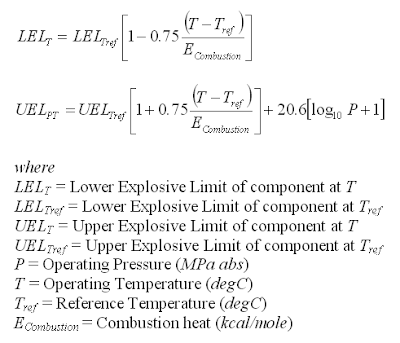
One shall take note that these equations are used for single component. For a mixtures, the LFL/LEL and UFL/UEL at operating pressure (P) and temperature (T) will be calculated using following equation (as discussed in "Estimate Mixture Flammability & Explosivity At Reference P & T":


Calculation Steps
2 steps in determining mixtures LFL/LEL and UFL/UEL at operating pressure (P) and temperature (T) .
(i) Estimate LFL/LEL and UFL/UEL at operating pressure (P) and temperature (T) for every component in a mixture
(ii) Estimate mixture LFL/LEL and UFL/UEL
Example
A mixture contains of Methane, Ethane and Propane with volume% of 20%, 20% and 60%. Estimate UEL at (i) 20 degC & 101.325 Pa, (ii) 70 degC & 3 MPa.
Data
Methane (C1)
UELC1,20C,1ATM = 15.0%, EC1,combustion = 212.79 kcal/mole
Ethane (C2)
UELC2,20C,1ATM = 12.4%, EC2,combustion = 372.81 kcal/mole
Propane (C3)
UELC3,20C,1ATM = 10.1%, EC3,combustion = 526.74 kcal/mole
Output
(i) UELMix at 20 degC & 101.325 Pa
(ii) UELMix at 70 degC & 3 MPa
UELC1,7oC,3MPa
= 15 x [1+0.75(70-20)/212.79]
+ 20.6 x [Log10(3)+1]
= 48.07 vol%
UELC2,7oC,3MPa
= 12.4 x [1+0.75(70-20)/372.81]
+ 20.6 x [Log10(3)+1]
= 44.08 vol%
UELC3,7oC, 3MPa
= 10.1 x [1+0.75(70-20)/526.74]
+ 20.6 x [Log10(3)+1]
= 41.25 vol%
UELMix,70C,3MPa = 1 / [ 0.2/48.07 + 0.2 /44.08 + 0.6 / 41.25 ]
Related Topic
- Subscribe FREE - Chemical Processing
- Tips on Succession in FREE Subscription
Earlier post "Estimate Mixture Flammability & Explosivity At Reference P & T" discussed about the Lower flammable limit (LFL) or Lower Explosive Limit (LEL) and Upper flammable limit (UFL) or Upper Explosive Limit (UEL) for single component fluid and mixture at reference pressure (Pref) and temperature (Tref). This post will discuss the way to correlate the LFL/LEL and UFL/UEL at Pref and Tref and operating pressure (P) and temperature (T) .
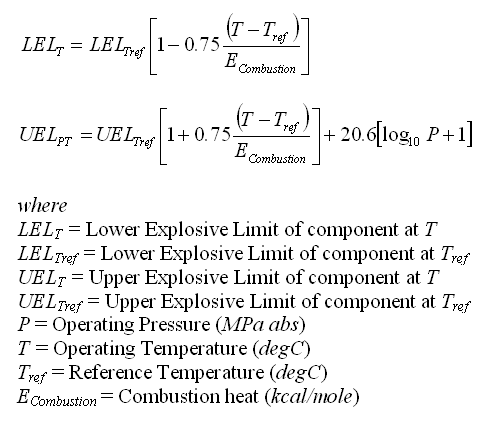
Temperature & Pressure Corrected LFL/LEL & UFL/UEL
Below are two equations may be used to correlate the LFL/LEL and UFL/UEL at Pref and Tref and operating pressure (P) and temperature (T).
Calculation Steps
2 steps in determining mixtures LFL/LEL and UFL/UEL at operating pressure (P) and temperature (T) .
(i) Estimate LFL/LEL and UFL/UEL at operating pressure (P) and temperature (T) for every component in a mixture
(ii) Estimate mixture LFL/LEL and UFL/UEL
Example
A mixture contains of Methane, Ethane and Propane with volume% of 20%, 20% and 60%. Estimate UEL at (i) 20 degC & 101.325 Pa, (ii) 70 degC & 3 MPa.
Data
Methane (C1)
UELC1,20C,1ATM = 15.0%, EC1,combustion = 212.79 kcal/mole
Ethane (C2)
UELC2,20C,1ATM = 12.4%, EC2,combustion = 372.81 kcal/mole
Propane (C3)
UELC3,20C,1ATM = 10.1%, EC3,combustion = 526.74 kcal/mole
Output
(i) UELMix at 20 degC & 101.325 Pa
UELMix = 1 / [ 0.2/15 + 0.2 /12.4 + 0.6 / 10.1 ]
UELMix = 11.25 vol% at 20 degC & 101.325 kPaA
(ii) UELMix at 70 degC & 3 MPa
UELC1,7oC,3MPa
= 15 x [1+0.75(70-20)/212.79]
+ 20.6 x [Log10(3)+1]
= 48.07 vol%
UELC2,7oC,3MPa
= 12.4 x [1+0.75(70-20)/372.81]
+ 20.6 x [Log10(3)+1]
= 44.08 vol%
UELC3,7oC, 3MPa
= 10.1 x [1+0.75(70-20)/526.74]
+ 20.6 x [Log10(3)+1]
= 41.25 vol%
UELMix,70C,3MPa = 1 / [ 0.2/48.07 + 0.2 /44.08 + 0.6 / 41.25 ]
UELMix,70C,3MPa = 43.02 vol% at 70 degC & 3 MPaA
Related Topic
