Sunday, November 30, 2008
 In earlier discussion "Simple Manual Method for Settle Out Condition Estimation", a manual method has been can be considered without using any Process Simulator. This method basically utilising universal gas law (PV=znRT) with the following basis and assumption :
- Vapor only system
- No condensation during the process
- Compressibility factor assumed same for condition before and after settle-out and assumed (z=1)
- Limited fluid with molecular weight is similar range. Higher the different, higher the deviation
Derivation
A system consists of n-section with pressure (Pi, kPag), temperature (Ti, K), Molecular weight (MWi), physical volume (Vi, m3) for i-section.
Number of mass in each i-section (before settle-out),
Volume at normal condition (Pi,n = 1.01325 bar & Ti,n = 273.15 K) for each i-section (before settle-out)
Total volume at normal condition (after settle-out)
mi x Ti for each i-section (before settle-out),
Total ms x Ts (after settle-out),
Thus, From [7] and [2],
Settle-out temperature (Ts),
Settle-out pressure (Ps),
There are five sets of system with each system has 3 section will be settled-out. The five set of fluid will have same pressure and temperature prior to settle out, however the composition of each section will be difference as follow :
Composition Set 1 :
Section 1 : Methane : 100%
Section 2 : Methane : 100%
Section 3 : Methane : 100%
Composition Set 2 :
Section 1 : Ethane : 100%
Section 2 : Methane : 100%
Section 3 : Methane : 100%
Composition Set 3 :
Section 1 : Ethane : 100%
Section 2 : Methane : 100%
Section 3 : Methane : 50%, Ethane : 20%, Propane : 30%
Composition Set 4 :
Section 1 : Propane : 100%
Section 2 : Propane : 100%
Section 3 : Methane : 50%, Ethane : 20%, Propane : 30%
Composition Set 5 :
Section 1 : Propane : 100%
Section 2 : Propane : 100%
Section 3 : Ethane : 40%, Propane : 60%
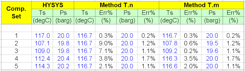
i) Settle-out pressure and temperature will not change with composition.
ii) if the composition are close between each sections, both T x n and T x m may be used.
iii) Accuracy for T x m are typically higher than T x n methods.
Related Topic
- Simple Manual Method for Settle Out Condition Estimation
- Adjusted Method For Compressor Settle Out (with Vapor & Liquid) Using HYSYS
- Simple Method For Compressor Settle Out (Vapor only) Using HYSYS
- Combine Anti-surge control (ASC) & Capacity Control (CC) Functions ?
- Saturate Dry Gas With Water in HYSYS
- Saturate Dry Gas With Water in HYSYS Using SATURATE Extension
- Useful Documentation for HYSYS ...
Labels: Compressor
Saturday, November 29, 2008
Natural gas may contains of other contaminants such as Carbon Dioxide (CO2), Hydrogen Sulfide (H2S), Water (H2O), Mercury (Hg), Nitrogen (N2), Helium (He), BTEX, etc. These contaminants potentially cause corrosion, cracking and freezing problem in the natural gas liquefaction process. and drop in Higher Heating Value (HHV). Thus they shall be removed prior to liquefaction process. Read more in "Typical Gas Processing Flow Scheme" and "Gas Processing, NGL Extraction & LPG Fractionation".
Entire LNG supply chain consist of LNG production, transportation and regassification process. Natural gas produced from gas well will be treated in order to remove contaminants as mentioned above prior feed to cryogenic section for liquefaction. In the liquefaction process, Natural gas is chilled down to about -160 degC. Ethane (C2), Propane (C3) and Butane (C4) will be recovered as Ethylene feedstock and production of Liquefied Petroleum Gas (LPG). Heavy hydrocarbon (C5+) will be removed from natural gas and sale as stablised condensate. In the process of liquefaction, the natural gas volume will reduce roughly about 600 times and this ease for LNG storage and transportation. Once the LNG is produced, it will store in LNG tank at atmospheric pressure prior pumped to LNG tanker for transportation.
LNG pumped into LNG tanker via LNG loading station will be send to customer. Good insulation is one of the key factor in keep LNG in liquid form during the transportation process. Any vaporized LNG will be compressed and used as fuel to generate power and drive all equipment in LNG tanker.
Once the LNG tanker arrived at LNG terminal, it is unloaded from the LNG tanker to the LNG storage tank. From the LNG storage, LNG is pumped and regassified using seawater or closed loop heated water. Vaporized natural gas is then injected into natural gas grid and deliver to customer.
Following are few video clips for the LNG supply chain, LNG liquefaction and terminal.
LNG supply chain
LNG Liquefaction Plant
LNG Terminal
Labels: gas processing, LNG
Wednesday, November 26, 2008
Aspen HYSYS has many support centers i.e. U.S., Canada, Mexican, Venezuela, France, UK, Egypt, South Africa, Malaysia, Singapore, Australia, etc. You may sometime would like quick information for the contact. HYSYS has one unique support email address : esupport@aspentech.com
However, you may like to obtain other information i.e contact number, fax number, etc for a particular nearest support center. This is especially important when you are outstation. One of the quickest way is from the HYSYS software itself. HYSYS has built-in these information in the HYSYS itself. See below image.
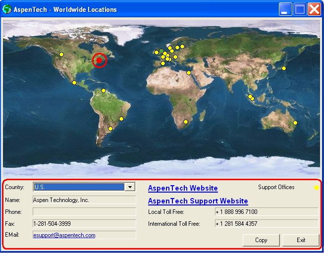
(Click to view larger image)
To launch this utility, just simply open the Help | About HYSYS..., pop-up display will show the HYSYS version/build. Then click the Technical Support at the bottom. You can obtain information for phone number, fax number, email address, toll free number, international toll free number, website address and support website address for all latest support centers.
Related Topic
Labels: HYSYS
Tuesday, November 25, 2008
| Build | Version |
| 7020 | V7.0 |
| 6924 | 2006.5 with CP3 |
| 2006.5 with CP2 | |
| 2006.5 with CP1 | |
| 2006.5 | |
| 6729 | 2006 with CP2 |
| 2006 with CP1 | |
| 6728 | 2006 |
| 6612 | 2004.2 with CP5 + Patch 6 |
| 2004.2 with CP5 | |
| 2004.2 with CP4 | |
| 2004.2 with CP3 | |
| 2004.2 with CP2 | |
| 2004.2 with CP1 | |
| 2004.2 | |
| 6510 | 2004.1 with CP1 |
| 2004.1 | |
| 6150 | 2004 |
| 5029 | 3.2 |
| 4815 | 3.1 |
| 4602 | 3.0.1 |
| 3874 | 2.4.2 |
| 3870 | 2.4.1 |
| 3806 | 2.2.2 |
| 3797 | 2.2 |
| 3216 | 2.1.3 |
| 3198 | 2.1.1 |
- Incompatibility HYSYS Version & Its File...What to do ?
- Mass Heat of Vaporization in HYSYS only for Pure Component
- Determine Latent Heat for Multi-Component and Relieving Area Using Rigorous Method in HYSYS
- Useful Documentation for HYSYS ...
- Extend of Pool Fire...
- How Fluid Characteristic affect 2 phase Relief via PSV on Liquid filled Vessel Exposing to External Fire
Labels: HYSYS
Sunday, November 23, 2008
 A reader MT (abbre.) has read "Why Restriction Orifice is some distance from Blowdown valve ?" and drop me a note. The question are more-or-less as follow :
Original Intention
Responses
Related Post
- Few Recommendation on Manual Blowdown Line
- A refresh to Process Engineer on few phenomenons in restriction orifice
- Bug in ASPENTECH HYSYS 2006 Dynamic Depressuring Fisher Valve model
- Controlled and Non-controlled Type Depressuring
- How to apply valve equation in HYSYS Depressuring ?
- Why Restriction Orifice is some distance from Blowdown valve ?
Labels: Depressurization, Material, Overpressure Protection, Safety
Saturday, November 22, 2008
This method is utilising universal gas law (PV=znRT) with the following basis and assumption :
- Vapor only system
- No condensation during the process
- Compressibility factor assumed same for condition before and after settle-out and assumed (z=1)
- Limited fluid with molecular weight is similar range. Higher the different, higher the deviation
Number of mole in each i-section (before settle-out),
ni = (Pi x Vi) / (zi x R x Ti).....[1]
Volume at normal condition (Pi,n = 1.01325 bar & Ti,n = 273.15 K) for each i-section (before settle-out)
ni x Ti for each i-section (before settle-out),
Total ns x Ts (after settle-out),
Thus, From [7] and [2],
Settle-out temperature (Ts),
Settle-out pressure (Ps),
Case Study
A methane compression system with the following conditions.
Suction :
Pressure, P1 = 5 barg
Temperature, T1 = 50 degC
Molecular weight, MW = 16.0429
Physical Volume, V1 = 1 m3
Compressor discharge (Hot) :
Pressure, P2 = 15 barg
Temperature, T2 = 150 degC
Molecular weight, MW = 16.0429
Physical Volume, V2 = 1 m3
Cooler discharge (Cool) :
Pressure, P3 = 15 barg
Temperature, T3 = 50 degC
Molecular weight, MW = 16.0429
Physical Volume, V3 = 1 m3
Using method as proposed in "Simple Method For Compressor Settle Out (Vapor Only) Using HYSYS", the settle out pressure and temperature are 11.73 barg and 86.3 degC. (see below image).

Using manual method as proposed above (program in Excel), the settle out pressure and temperature are 11.67 barg and 85.7 degC. (see below image).

The percentage error are 0.5% and 0.7% for pressure and temperature respectively.
This shown the method is reasonable.
Related Topic
- Adjusted Method For Compressor Settle Out (with Vapor & Liquid) Using HYSYS
- Simple Method For Compressor Settle Out (Vapor only) Using HYSYS
- Combine Anti-surge control (ASC) & Capacity Control (CC) Functions ?
- Saturate Dry Gas With Water in HYSYS
- Saturate Dry Gas With Water in HYSYS Using SATURATE Extension
- Useful Documentation for HYSYS ...
Labels: Compressor
Friday, November 21, 2008
Tips on Succession in FREE Subscription
Subscribe FREE - Processing Magazine
Some time you received an HYSYS file (ABC.hsc) from contractor or client, you open the file using a particular version (i.e. HYSYS 3.2), you may experience the HYSYS failed to open the file. Reason being you are using older version/build of HYSYS (i.e 3.2 ) to open a newer version/build of HYSYS (i.e 2006).
There are several questions may be raised :
i) How to know which version/build of HYSYS that you are using ?
ii) How can you know which version/build of HYSYS a case was created ?
iii) How to open a newer version/build of HYSYS with older version/build of HYSYS ?
HYSYS version
To know which version of HYSYS you are using, just simply open the Help | About HYSYS..., pop-up display will show the HYSYS version/build. The following image shows it is HYSYS version 3.2 (Build 5029).

HYSYS Version of Created File
To know which version the file was created, first you need to make small changes in HYSYS Preferences. Click Tools | Preferences, the Session Preferences pop-up will be displayed. Click Files tab and select HYPROTECH file Picker on the top, then click the Save Preferences Set. See
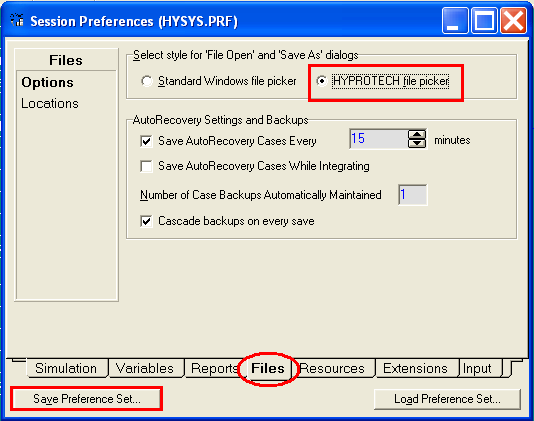
Now click the File | Open | Case, the file open pop-up is displayed. You will notice the version / build of the file created in HYSYS.

(Click to view large image)

Open File Created in Newer Version with Older Version of HYSYS
The topic has been discussed in earlier post "Open HYSYS File in Older Version of HYSYS".
To get more tutorial and information related to HYSYS, check out "Useful Documentation for HYSYS ...".
Related Topic
- Mass Heat of Vaporization in HYSYS only for Pure Component
- Determine Latent Heat for Multi-Component and Relieving Area Using Rigorous Method in HYSYS
- Useful Documentation for HYSYS ...
- Extend of Pool Fire...
- How Fluid Characteristic affect 2 phase Relief via PSV on Liquid filled Vessel Exposing to External Fire
- Definition of Terms Related to PRESSURE
Labels: HYSYS
Thursday, November 20, 2008
In the Proceedings of the National Academy of Sciences (PNAS) the week of Aug. 18, the team describes assembling and successfully testing two of the three key components of a battery. A complete battery is on its way.
"To our knowledge, this is the first instance in which microcontact printing has been used to fabricate and position microbattery electrodes and the first use of virus-based assembly in such a process," wrote MIT professors Paula T. Hammond, Angela M. Belcher, Yet-Ming Chiang and colleagues. Read more in MIT Tech Talk.
Related Topic
- Tree Power
- Nanowire battery... High Potential of Replacing Lithium Battery
- Fabric Generate Power Caught Global Interests...
- "Power shirt"
- Own Your Fuel Filling Station in Your Garage
- Euro 6 Million Supporting Nanotechnology
- Nanowerk - NanoTech News & Database Center
- Nano Technology - Revolution in Material Selection
Labels: Green Technology, Technology
Tuesday, November 18, 2008
Download
If you aware of any other method, please share with us.
Related Topic
- Guideline on Quick Determination of Flare Stack Support Type
- Must Read Flare Handbook
- Why not bury flare pipe header ?
- Use Ultra-Sonic Flowmeter in FLARE Gas Header for emission monitoring
- FLARE combustion efficiency
- Factors and Criteria for Vent Stack Design
Labels: Flare, FLARENET, Process simulation
Monday, November 17, 2008

Related Topic
- Nanowire battery... High Potential of Replacing Lithium Battery
- Fabric Generate Power Caught Global Interests...
- "Power shirt"
- Own Your Fuel Filling Station in Your Garage
- Euro 6 Million Supporting Nanotechnology
- Nanowerk - NanoTech News & Database Center
- Nano Technology - Revolution in Material Selection
Labels: Green Technology, Technology
Sunday, November 16, 2008

Recommended :
Subscribe FREE - Processing Magazine
Check valves or Non-return valves (NRV) are normally installed in piping to avoid back flow. Rotating equipment such as pump, compressor, etc will always be equipped with NRV(s) on the discharge to avoid back flow when rotating equipment is shut. Back flow creates severe surging to the rotating equipment and potentially damage the equipment. In certain process system, NRV will be employed to avoid contamination, overheating, etc due to back flow.Check valves or Non-return valves (NRV) is basically an automatic valve open to allow forward flow and close to against reverse flow. In principle, it split into four basic types. There are swing, dual-plate, tilting disc and lifting type. Wrong selection of check valve type can leads to operability problem, leakage and continual maintenance issue.
Lift Check valves
- higher pressure drop is expected.
- equipped with small return spring to facilitate valve closure on reverse flow
- two type of seat. hard seat for for high differential pressure sealing and resilient seat for low differential pressure sealing
- shortest travel length. Fastest response.
- excellent performance for low and/or pulsating flows
- not good for fluid with particles
- Body install horizontal with disc / piston vertically
- Small check valve range from 1/2" to 2" lift piston type check valve
- Prefer operate in full open position
Minimum Recommended Line Velocity, Vmin (ft/s) = 12 SQRT (v)
where
v = Specific Volume of the Fluid (ft3/lb)

Swing Check Valve
- Tight sealing / shut-off
- Low pressure drop
- Susceptible to water hammer
- Not good for low flow and/or pulsating flow
- Vertical (upward flow) & horizontal installation
- Easiest check valve to maintain
- Prefer operate in full open position
Swing check valves should be sized such that the flow velocity in the line is sufficient to hold the disc in the fully open position.
Minimum Recommended Line Velocity, Vmin (ft/s) = 75 SQRT(v)
where
v = Specific Volume of the Fluid (ft3/lb)

Dual plate Check valve
The characteristic of dual plate check valve is pretty same as swing check valve.
- low pressure drop
- Not good for low flow and/or pulsating flow
- Vertical (upward flow) & horizontal installation
- Faster opening and closure compare to swing check valve
- Susceptible to water hammer (lesser than Swing check valve)
- Prefer operate in full open position

Tilting Disc Check Valves
- Fast opening and closing without damage to disc and seat
- Stable at low and pulsating flows
- Moderate pressure drop. Lower than lifting check valve but higher than swing check valve
- Vertical (upward) & horizontal installation
- Moderate tight sealing
- Prefer operate in full open position
Minimum Recommended Line Velocity, Vmin (ft/s) = 24 sqrt (v)
where
v = Specific Volume of the Fluid (ft3/lb)

There are four (4) main criteria shall be considered for the selection of check valve type :
- non-slam characteristic
- pressure loss
- cost
- application
Related Post
- Several Strategies To Minimize Relief Capacity in Back-Flow Scenario
- How to predict Check Valve Slam ?
- How to Select a Check Valve (NRV) Quantitatively ?
- Why Redundant NRV in Series within a Line ?
- Why bypass Non-Return Valve (NRV) ?
- Potential Problem associate with Double NRV in Series within a Line
- Basis & Tips on Setting Centrifugal Pump "Warming" Recycle Flow
Labels: Fluid Flow, Hydraulic, NRV, Surge
Friday, November 14, 2008
- Tips on Succession in FREE Subscription
- Subscribe FREE - Hydrocarbon Engineering
 Since the released of this article "Determine Latent Heat for Multi-Component and Relieving Area Using Rigorous Method in HYSYS", a few young engineers raised a question. The proposed method does not work for pure component i.e. pure propane. How shall i obtain the latent heat of pure component using HYSYS ?

Important Note :
For pure component, latent heat of vaporization can be obtained by Vapor Mass Enthalpy (Hv) minus Liquid Mass Enthalpy (Hl).
For multi-component, latent heat of vaporization is NOT advisable to obtain by Vapor Mass Enthalpy (Hv) minus Liquid Mass Enthalpy (Hl). Rigorous method proposed in "Determine Latent Heat for Multi-Component and Relieving Area Using Rigorous Method in HYSYS" can be used.
Related Topic
Labels: Fire, HYSYS, Overpressure Protection, Pressure Relief Device
Thursday, November 13, 2008
- Maximum Allowable Working Pressure (MAWP)
- Design Pressure (PD)
- Maximum Allowable Operating Pressure (MAOP)
- Maximum Operating Pressure (PO,Max)
- Normal Operating Pressure (PO)
- Minimum Operating Pressure (PO,Min)
- Minimum Allowable Operating Pressure (MinAOP)
Recommended :
- Subscribe FREE - Chemical Processing
- Tips on Succession in FREE Subscription
A mechanical engineer may have different understanding than a process engineer. A process engineer from an organization may have slightly different understanding than a process engineer from another organization. A process engineer educated and/or practising engineering in a country i.e China may have different interpretation than another process engineer educated and / or practising engineering in another country i.e. USA, UK, etc. This always creates a lot of confusion, unnecessary argument and rework. In worst event could lead to hazard. Thus, first far most important thing is to define correctly the meaning of each terms so that everyone have same understanding.
Following are the simple definition of above mentioned terms. Whenever a post contains one or more of these terms, the following shall be referred.
Normal Operating Pressure (PO) - System pressure as expected to be operated at during normal operation throughout the design life of the system.
Maximum Operating Pressure (PO, Max) - Maximum system pressure as expected during normal operation, may occur in some process transient period or different operating mode or campaigns and it built into the design to cater for any uncertainties due to start-up, fouled, decayed, etc. It provides some level of flexibility for a proper operation of the system throughout the entire life of the system.
Minimum Operating Pressure (PO, Min) - Minimum system pressure as expected during normal operation, may occur in some process transient period or different operating mode or campaigns and it built into the design to cater for any uncertainties due to start-up, fouled, decayed, etc. It provides some level of flexibility for a proper operation of the system throughout the entire life of the system.
Maximum Allowable Operating Pressure (MAOP) - Maximum system pressure that can be allowed to ensure a proper operation of an a device or system.
Minimum Allowable Operating Pressure (MinAOP) - Minimum system pressure that can be allowed to ensure a proper operation of an a device or system.
Design Pressure (PD) - A pressure chosen / specified (normally chosen by process engineer) to have certain margin (i.e. 10%) above the PO,Max (or MAOP). It is a maximum pressure in the system that :
- is NOT expected during normal operation
- may only occur during emergency situation such as fire, loss of utilities, valve failure, any abnormal operation corresponding to a short duration, mal-operation, etc
Design pressure becomes MINIMUM pressure that can be hold by any components within the system without mechanical failure. It is used to define the minimum MAWP of components within the system. For example, design pressure is used to calculate minimum vessel wall thickness.
Maximum Allowable Working Pressure (MAWP) - A maximum gauge pressure permissible by a equipment / device (at coincident temperature specified for that pressure) and is governed by code i.e. ASME, JIS, GB, etc
In many cases...
MinAOP <= PO,Min <= PO <= PO,Max < MAOP < PD <= MAWP
Example :(Note : all parameters have been selected arbitrary. Just for illustration only.)
- Maximum Allowable Working Pressure (MAWP) = 12 barg
- Design Pressure (PD) = 11 barg
- Maximum Allowable Operating Pressure (MAOP) = 10 barg (~90% of 11 barg)
- Maximum Operating Pressure (PO,Max) = 8 barg
- Normal Operating Pressure (PO) = 7 barg
- Minimum Operating Pressure (PO,Min) = 6 barg
- Minimum Allowable Operating Pressure (MinAOP) = 5 barg
- Several Strategies To Minimize Relief Capacity in Back-Flow Scenario
- Only Consider Non-Recoverable Losses in PSV Inlet Line Loss Determination
- How to Resolve Issue with PSV Inlet Line Loss Exceeded 3% of Set pressure
- Concerns & Recommendations on PSV INLET line
- Few Concerns & Recommendations of PSV Discharge Tail pipe
- Relate PSV Relieving Flow to Stamped Capacity
Labels: Design, Overpressure Protection
Wednesday, November 12, 2008

FREE Chemical Engineering Digital Issue for November 2008 has just been released !
Chemical Engineering magazine has just released November 2008 issue. If you are the subscriber of Chemical Engineering, you shall received similar notification.
Interesting articles for this month:
2008 Salary Report Ch.E.s
Wonder when the CPI will feel the hit of the weakening world economy
Process Modeling Moves Center-Stage
A model solution for the CPI: Reducing risk while increasing profit
When Size Matters
Particle sizing equipment gets updated to meet the changing needs of the CPI
Biodiesel Production
This one-page guide illustrates the process of biodiesel production by basecatalyzed transesterification of vegetable oil
Condition-Based Maintenance Management Enhances Reliability
Understand reliability, condition monitoring and maintenance management to keep rotating equipment in top form
Get More From Vertical Thermosiphon Reboilers
The effects of three different heat-transfer-enhancement devices are outlined here
Temperature and Pressure Measurement
Calibrate high-quality thermometers with this instrument; A pressure transducer for hazardous applications is introduced; Ultra-compact pressure transmitters offer
If you yet to be subscriber of Chemical Engineering, requested your FREE subscription via this link (click HERE). Prior to fill-up the form, read "Tips on Succession in FREE Subscription".
Related Post
- 3 Most Important & FREE Magazines That I Read...
- Non - Technical Quick References for a Chemical & Process Engineers
- R&D engineer, Academician and Student...Don't miss this !
- More You Share More You Learn
- Knowledge is Own by Everyone but Not Someone
- Tips on Succession in FREE Subscription
Labels: E-Doc, Education, Learning
Tuesday, November 11, 2008
It is correct that the simple method is simplified version for VAPOR only Settle out condition. Nevertheless, minimum adjustment to the method enable the method to be used for condition with VAPOR and LIQUID. First refer to following image.

Step 1 : Compressor Suction. Estimate physical volume of vapor (Vv1) and liquid (Vl1).
Step 3 : Air Cooler Downstream. Estimate physical volume of vapor (Vv3) and liquid (Vl3).
The remaining steps are same as "Simple Method For Compressor Settle Out Using HYSYS" by adjusting Settle Out Cond Actual Volumetric Flow same as Vv1+Vl1+V2+Vv3+Vl3.
Related Topic
- Simple Manual Method for Settle Out Condition Estimation
- Simple Method For Compressor Settle Out Using HYSYS
- Combine Anti-surge control (ASC) & Capacity Control (CC) Functions ?
- Saturate Dry Gas With Water in HYSYS
- Saturate Dry Gas With Water in HYSYS Using SATURATE Extension
- Useful Documentation for HYSYS ...
- Depressuring - Save Some Time in HYSYS - FLARENET Iteration
Labels: Compressor, HYSYS, Process simulation
