Wednesday, September 29, 2010
Earlier post "How Boil-Off-Gas (BOG) is Generated" and "Quick Way to Estimate BOG" discussed several ways result Boil-Off-Gas (BOG) generation and simple way to estimate BOG. Heat leak into piping wrapped with Cold insulation is one of the way possibly result significant BOG generation, in particular in large base load plant where product is loaded into ship. Long rundown and loading line from production plant and from storage tank to ship can generate significant BOG. Proper selection and determination of insulation thickness can minimize BOG generation economically.
Overall heat transfer cooefficient estimate from Nusselt number :


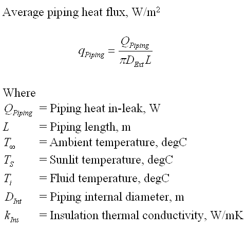
Piping in-leak heat can be estimated with following equation
 with heat flux

Piping external diameter = 152.4 mm
Piping length = 100 m
Insulation material = Polyisocyanurate
Insulation thermal conductivity = 0.023 W/mK
Assumed Insulation thickness = 60 mm
Piping external diameter (including insulation) = 152.4 + 2x60 = 272.4mm
Air :
Air Velocity = 5 m/s
Air Thermal Conductivity = 0.029 W/mK
Air specific heat = 1009 J/kgK
Air density = 1.038 kg/m3
Air viscosity = 0.02 cP
Calculation :
Air Prandtle Number = 0.6959
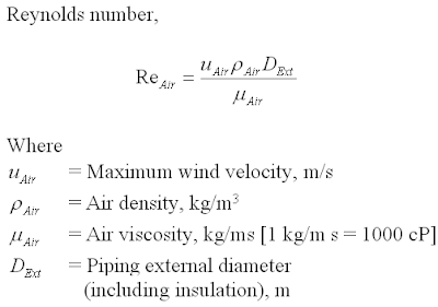
Air Reynolds Number =70687.8
Overall Heat transfer Coefficienct = 18.096 W/m2K
Piping In-leak heat = 2125.72 W
Piping surface area = 85.58 m2
Average heat flux = 24.8 W/mK < 25 W/mK...OK
Similar calculation applied to 1" to 28"
1" - 50mm insulation thickness
2" - 50mm insulation thickness
3" - 60mm insulation thickness
4" - 60mm insulation thickness
6" - 60mm insulation thickness
8" - 70mm insulation thickness
10" - 70mm insulation thickness
12" - 70mm insulation thickness
16" - 70mm insulation thickness
20" - 70mm insulation thickness
24" - 70mm insulation thickness
28" - 70mm insulation thickness
Key Rule
Rule of thumb for economic heat flux for heat in-leaks range from 25 to 35 W/m2. This is the key rule to derive an economic insulation for cold service whilst minimizing BOG generation.Recommended :
- Subscribes to FREE Hydrocarbon Processing
- Tips on Succession in FREE Subscription
 Insulation Material & Thermal Conductivity
Common insulation material used in cold services (sometime called cryogenic service in extremely low temperature case e.g. LNG with operating temperature of approximately -162 degC) are typically Polyurethane and Polyisocyanurate Foam (PIR). These insulation material have very low conductivity minimizing heat from ambient entering cold fluid. Typical thermal conductivity for these material is approximately 0.023 W/mK @ 20 degC.- Subscribes to FREE Hydrocarbon Processing
- Tips on Succession in FREE Subscription
Insulation Material & Thermal ConductivityInsulated Piping In-Leak Heat
Estimation of piping in-leak heat from ambient starts with estimation of heat transfer coefficient using Nusselt number which is a function of Prandtle and Reynolds number.Overall heat transfer cooefficient estimate from Nusselt number :

where Prandtle number

and Reynolds number

Piping in-leak heat can be estimated with following equation

Case study
Piping nominal size = 6"Piping external diameter = 152.4 mm
Piping length = 100 m
Insulation material = Polyisocyanurate
Insulation thermal conductivity = 0.023 W/mK
Assumed Insulation thickness = 60 mm
Piping external diameter (including insulation) = 152.4 + 2x60 = 272.4mm
Air :
Air Velocity = 5 m/s
Air Thermal Conductivity = 0.029 W/mK
Air specific heat = 1009 J/kgK
Air density = 1.038 kg/m3
Air viscosity = 0.02 cP
Calculation :
Air Prandtle Number = 0.6959
Air Reynolds Number =70687.8
Overall Heat transfer Coefficienct = 18.096 W/m2K
Piping In-leak heat = 2125.72 W
Piping surface area = 85.58 m2
Average heat flux = 24.8 W/mK < 25 W/mK...OK
Similar calculation applied to 1" to 28"
1" - 50mm insulation thickness
2" - 50mm insulation thickness
3" - 60mm insulation thickness
4" - 60mm insulation thickness
6" - 60mm insulation thickness
8" - 70mm insulation thickness
10" - 70mm insulation thickness
12" - 70mm insulation thickness
16" - 70mm insulation thickness
20" - 70mm insulation thickness
24" - 70mm insulation thickness
28" - 70mm insulation thickness
Labels: gas processing, LNG
Sunday, August 29, 2010
Earlier post "How Boil-Off-Gas (BOG) is Generated" has discussed several ways can result Boil-Off-Gas generation. They are listed below :
- vaporized vapor due to barometric pressure decrease
- vaporized vapor due to ambient temperature increase
- cryogenic fluid rundown piping
- cryogenic fluid circulation / loading line
- ship / truck loading arm
- cryogenic fluid storage tank
- cryogenic fluid rundown pump
- cryogenic fluid in-tank pump
- flashed non-condensable gasses
- negative Joule-Thompson effect
- "hot" rundown cryogenic liquid into "cold" cryogenic liquid
- cooling of loading arm
- cooling of ship / truck
This post will discuss quick way to estimate BOG flow.
Recommended :
- Subscribes to FREE Hydrocarbon Processing
- Tips on Succession in FREE Subscription
Atmospheric pressure at sea level is 101.325 kPa abs. Atmospheric pressure is reduced with increase in altitude. For example, at elevation of 1,000 meter, the atmospheric pressure can be as low as 89.81 kPa abs. Cryogenic storage may be designed to operate between 50-70 mbar gauge. If the cryogenic storage tank is at beach (sea level), the operating pressure in the tank is approximately 106.325 - 108.325 kPa abs. If this cryogenic storage is at 1,000 meter, the operating pressure in the tank is approximately 94.81 - 96.81 kPa abs. Lower operating pressure in tank can results higher vaporization and more BOG is generated. Therefore, it is always a good practice to use absolute pressure whenever dealing with cryogenic storage tank. Correct pressure modeling in process simulator is extremely important in finding quantity of BOG generated.
Heat leaks into cryogenic fluid can be via rundown / circulation piping, loading arm & storage tank. Proper selection, installation and maintenance of insulation is one of the key factor in minimizing heat leaks into cryogenic system, hence BOG generation. Besides insulation, other external factors such as wind speed, solar radiation, ambient temperature, sand conductivity and etc, affect heat leak. However, these factors are hard to be managed. Heat leaks into system can be calculated by considering heat conduction, convection and radiation. However, this type calculation involve a lot of uncertainties, assumption and rather complicated. Based on past experiences, an approximate method using vaporization coefficient in determining BOG generation due to heat leaks via storage tank, may be considered during conceptual phase.

Vaporization coefficient (k) may range from 0.04% to 0.06% for LNG whilst 0.06% to 0.1% for Propane, Butane and LPG. One may take note that above are typical for large storage tank e.g. 160,000m3. Higher k factor should be used for smaller storage. For example, 60,000m3, k of 0.08 - 0.1% may be considered.
Above equation is applicable to storage tank which is low surface area-to-volume ratio. However, piping with very low volume and high surface area may experience higher heat input comparatively. Following equation may be used to estimate BOG generated due to piping.
 Average heat flux subject to piping diameter. In general, kp of 25 -35 W/m2 may be considered.
Energy is transferred to pump to move quantity of liquid. Part of the energy will loss due to deficiency. and results BOG generation. Following equation may be considered to estimate BOG generated due to pump deficiency.

Pump efficiency can be range from 55% - 75% for common centrifugal pump.
Cryogenic liquid produced from main plant and transfer to cryogenic liquid storage tank. Inflow liquid will displaced vapor and add-on to BOG generation. Following equation may be used.

Other factors result generation of flashed vapor or BOG generation such as present of non-condensable gasses, negative Joule-Thompson effect and "hot" rundown cryogenic liquid into "cold" cryogenic liquid, will possibly be modeled in process simulator.
Cooling of loading arm and tank in ship / truck may generate substantial amount of vapor initially and reduce as loading arm and tank is cooled. This BOG generation may required dynamic simulation which will not be presented in this post.
- Subscribes to FREE Hydrocarbon Processing
- Tips on Succession in FREE Subscription
Atmospheric pressure at sea level is 101.325 kPa abs. Atmospheric pressure is reduced with increase in altitude. For example, at elevation of 1,000 meter, the atmospheric pressure can be as low as 89.81 kPa abs. Cryogenic storage may be designed to operate between 50-70 mbar gauge. If the cryogenic storage tank is at beach (sea level), the operating pressure in the tank is approximately 106.325 - 108.325 kPa abs. If this cryogenic storage is at 1,000 meter, the operating pressure in the tank is approximately 94.81 - 96.81 kPa abs. Lower operating pressure in tank can results higher vaporization and more BOG is generated. Therefore, it is always a good practice to use absolute pressure whenever dealing with cryogenic storage tank. Correct pressure modeling in process simulator is extremely important in finding quantity of BOG generated.Heat leaks into cryogenic fluid can be via rundown / circulation piping, loading arm & storage tank. Proper selection, installation and maintenance of insulation is one of the key factor in minimizing heat leaks into cryogenic system, hence BOG generation. Besides insulation, other external factors such as wind speed, solar radiation, ambient temperature, sand conductivity and etc, affect heat leak. However, these factors are hard to be managed. Heat leaks into system can be calculated by considering heat conduction, convection and radiation. However, this type calculation involve a lot of uncertainties, assumption and rather complicated. Based on past experiences, an approximate method using vaporization coefficient in determining BOG generation due to heat leaks via storage tank, may be considered during conceptual phase.

Vaporization coefficient (k) may range from 0.04% to 0.06% for LNG whilst 0.06% to 0.1% for Propane, Butane and LPG. One may take note that above are typical for large storage tank e.g. 160,000m3. Higher k factor should be used for smaller storage. For example, 60,000m3, k of 0.08 - 0.1% may be considered.
Above equation is applicable to storage tank which is low surface area-to-volume ratio. However, piping with very low volume and high surface area may experience higher heat input comparatively. Following equation may be used to estimate BOG generated due to piping.

Energy is transferred to pump to move quantity of liquid. Part of the energy will loss due to deficiency. and results BOG generation. Following equation may be considered to estimate BOG generated due to pump deficiency.

Pump efficiency can be range from 55% - 75% for common centrifugal pump.
Cryogenic liquid produced from main plant and transfer to cryogenic liquid storage tank. Inflow liquid will displaced vapor and add-on to BOG generation. Following equation may be used.

Other factors result generation of flashed vapor or BOG generation such as present of non-condensable gasses, negative Joule-Thompson effect and "hot" rundown cryogenic liquid into "cold" cryogenic liquid, will possibly be modeled in process simulator.
Cooling of loading arm and tank in ship / truck may generate substantial amount of vapor initially and reduce as loading arm and tank is cooled. This BOG generation may required dynamic simulation which will not be presented in this post.
Related Topics
- How Boil-Off-Gas (BOG) is Generated
- Techniques to Achieve Cryogenic Temperature
- PFHE & CWHE Comparison in LNG Plant
- LNG and Supply Chain
- Gas Processing, NGL Extraction & LPG Fractionation
- Typical Gas Processing Flow Scheme
- Typical Refinery Flow Scheme
- Floating Gas Refinery Unit
- Use Wobbe Index to Manage Fuel Quality to Gas Burner
Labels: gas processing, LNG
Monday, August 23, 2010
Recommended :
- Subscribes to FREE Hydrocarbon Processing
- Tips on Succession in FREE Subscription
Liquefied Petroleum Gas (LPG) contains mainly Propane (C3) and Butane (i-C4 & n-C4), Liquid Ethylene (C2=) and Liquefied Natural Gas (LNG) contains mainly Methane will evaporate at ambient condition e.g. 20 degC @ 101.325 kPag.
LPG, Liquid Ethylene and LNG can be stored in refrigerated vessel at its bubble point and atmospheric pressure. Their bubble point can be as low as -40, -104 and -162 degC are commonly known as cryogenic temperature and fluid as cryogenic fluid.
- Subscribes to FREE Hydrocarbon Processing
- Tips on Succession in FREE Subscription
Liquefied Petroleum Gas (LPG) contains mainly Propane (C3) and Butane (i-C4 & n-C4), Liquid Ethylene (C2=) and Liquefied Natural Gas (LNG) contains mainly Methane will evaporate at ambient condition e.g. 20 degC @ 101.325 kPag.LPG, Liquid Ethylene and LNG can be stored in refrigerated vessel at its bubble point and atmospheric pressure. Their bubble point can be as low as -40, -104 and -162 degC are commonly known as cryogenic temperature and fluid as cryogenic fluid.
Heat leaks into the cryogenic fluid will results vaporization and lead to Boil-Off-Gas (BOG) generation. Other than heat leak, there are other scenarios can lead to BOG generation :
- vaporized vapor due to barometric pressure decrease
- vaporized vapor due to ambient temperature increase
- cryogenic fluid rundown piping
- cryogenic fluid circulation / loading line
- ship / truck loading arm
- cryogenic fluid storage tank
- cryogenic fluid rundown pump
- cryogenic fluid in-tank pump
- flashed non-condensable gasses
- negative Joule-Thompson effect
- "hot" rundown LNG into "cold" LNG
- cooling of loading arm
- cooling of ship / truck
Vaporized vapor due to barometric pressure decrease & ambient temperature increase
Environment pressure and temperature change affects BOG generation. Maximum BOG generation during summer, noon and high elevation (with low barometric pressure). On the other hand, minimum BOG generation during winter, mid-night and near sea side (high barometric pressure).
Heat leaks into Cryogenic fluid rundown piping, circulation / loading line, ship / truck loading arm & storage tank
Ambient heat leaks cryogenic fluid will be limited by insulation layer. Heat leaks into subjects to insulation thickness, thermal conductivity, installation quality, etc. Higher insulation thickness, lower thermal conductivity, high installation quality and etc maintain good heat insulation and reduce BOG generation.
Heat generated by rundown pump & in-tank pumpand leaks into Cryogenic fluid
Pumps is required for transferring cryogenic liquid from production plant to storage tank and from storage tank to ship/truck. Pump will absorb power to move cryogenic fluid and any deficiency will generate heat and it will transfer into cryogenic fluid. Pump heat leaks subject to pump capacity, develop head and efficiency. Larger pump, higher head and lower efficiency lead to excess heat generation and leaks into cryogenic fluid.
Flashing of non-condensable gasses
Present of inert / non-condensable gasses such as nitrogen, carbon monoxide in cryogenic fluid may flash in the storage tank.
Negative Joule-Thompson effect
Another phenomenon is negative Joule Thompson (negative JT) where pressure decrease in rundown line lead to higher temperature. Typical gas is Hydrogen.
"Hot" rundown into "cold" cryogenic fluid
Hot cryogenic fluid from one train with hotter temperature which carries heat and rundown into cryogenic tank with colder temperature can results vaporization.
Hot cryogenic fluid from one train with hotter temperature which carries heat and rundown into cryogenic tank with colder temperature can results vaporization.
Cooling of loading arm & tank in ship / truck
Loading arm is heated to ambient temperature when it is unrest for long time. Cryogenic tank in ship / truck is heated by ambient when it is returned with empty tank. All loading arm and tank in ship/truck will needs cooling prior to storage. Large amount of BOG is generated during cooling time.Coming topic will discuss quick way to estimate BOG rate.
Related Topics
Labels: gas processing, LNG
Sunday, August 8, 2010

Georges Claude, in 1902 produced a piston expansion engine working at the low temperatures required for the liquefaction of air. The increase in cooling effect over the Joule-Thomson nozzle expansion of the Linde-Hampson designs. The expansion through an expansion valve is an irreversible process. energy is removed from the gas stream by allowing it to do some work in an expansion engine or expander.

Recommended :
The process is based on a suitable modified Claude cycle which minimizes the umber of heat exchangers and also takes care to accommodate the in house developed turbo xpander. The process design is carried out using the standard calculation procedure and is validated by using process simulation software, Aspen Hysys. parametric analysis is carried out to access the role of different component efficiencies in predicting overall system efficiency at the design and off design conditions. In this analysis, the available turbo expander efficiency is considered to evaluate the feasible heat exchanger efficiency in order to optimize the plant efficiency. The thermodynamic parameters (temperature, pressure, pinch point temperature) are evaluated to obtain the optimum mass fraction through turbo expander for maximum liquid yield. This investigation not only gives the analysis of nitrogen liquefier, but also it will act as a basic frame work for any liquefier and helium liquefier in particular as a future mission.
Download
Related Topics
Labels: gas processing, LNG
Friday, December 25, 2009
Recommended :
Natural gas is known as one of the world’s cleanest fossil fuel and it burns to form Carbon Dioxide (CO2) and Water (H2O) without or with minimal smoke subject to composition. Increased world crude demand and price has slowly pushing energy consumers shift from conventional crude based fuel i.e. gasoline, kerosene, etc to natural gas based fuel i.e. liquefied natural gas (LNG), liquefied petroleum gas (LPG), Gas-to-liquid (GTL), etc.
Natural gas conventionally is distributed in gas network. Distribution by gas network will only feasible and cost effective in limited distance i.e. 3000-3500 km. Natural gas may be compressed and stored in very high pressure storage tank. However, high capital cost in high pressure storage tank and high safety risk has driven users look for better transportation and storage option. Liquefying natural gas is one of the option can be most feasible and cost effective. Natural gas in the form of LNG,cooled to minus 160-163 degree Celcius at atmospheric pressure, approximate 600 times smaller than its gaseous state, make it so cost effective in storage and long distance transportation.
In recent net search, there are number of LNG related video clips available in educating, promoting and awareness creation about LNG.
Researchers at Idaho National Laboratory have developed a small-scale Liquid Natural Gas systems to expand the use of clean fuel at an affordable cost.
Pulse of the Port details a proposal for a Liquified Natural Gas Plant at the Port of Long Beach.
One of the largest gas field in the world is located in the sea between Qatar and Iran. Qatar is expanding its fleet of ships to deliver liquified natural gas (LNG) to world market.
BP LNG Tangguh
Terminal operated by Terminale LNG Adriatico Srl, a company owned by Qatar Terminal Limited (45%), ExxonMobil Italiana Gas (45%) and Edison (10%), will be the first offshore facility in the world for unloading, storing and regasifying natural gas. This facility will thus play a key role in increasing Italys energy security and will make the Italian natural gas market more competitive.
The world's largest oil and gas project Sakhalin-2 has begun to produce LNG for the world market. Russia's first LNG cargo will be delivered to Japan.
Second LNG tanker for the Sakhalin-2 field
Labels: gas processing, LNG
Monday, June 22, 2009
Display problem ? Click HERE
Recommended :Liquefied Natural Gas (LNG) is one of the cleanest energy among all other energy sources.LNG and Supply Chain discussed briefly entire production, transportation, receiving and distribution path of LNG. There are still many peoples who are safety, environment & security concerns, not agreeing with the LNG production as discussed in "LNG SES Issues...".
Liquefy Natural gas is a process of cooling down the natural gas to form liquid for easy storage and transportation. There are few ways to cool down natural gas. Typically are mechanical refrigeration, JT valve and expansion turbine. More discussion in "Techniques to Achieve Cryogenic Temperature". Nowadays, liquefying LNG processes generally adopting combination of two or three techniques as discussed above. Following is a tabulation of a few well-known LNG processes.
Liquefy Natural gas is a process of cooling down the natural gas to form liquid for easy storage and transportation. There are few ways to cool down natural gas. Typically are mechanical refrigeration, JT valve and expansion turbine. More discussion in "Techniques to Achieve Cryogenic Temperature". Nowadays, liquefying LNG processes generally adopting combination of two or three techniques as discussed above. Following is a tabulation of a few well-known LNG processes.
| Process | C3MR | Cascade | SMR | DMR | MFC | N2 Exp |
| Thermal Eff. | High | High | Med. | High | High | Low |
| Equip. no | Med. | High | Low | Med. | Med. | Med. |
| Precooling HX | Kettle | Core-in -Kettle | Plate-fin | Spiral Wound | Plate-fin | Kettle |
| Liq. HX | Spiral Wound | Core-in -Kettle Plate-fin | Plate-fin | Spiral Wound | Spiral Wound | Plate-fin |
| Refrig. Storage | Large | Large | Med. | Med. | Med. | None |
| CAPEX | Med. | Med. | Low | Med. | Med. | High |
Related Topics
Labels: gas processing, LNG
Saturday, December 20, 2008
Display problem ? Click HERE
Recommended :
Subscribes to FREE Hydrocarbon Processing
Present of Hydrogen Sulfide (H2S) and Carbon Dioxide (CO2) in wet natural gas will cause severe metal stress cracking and corrosion possibly leads to severe leakage. Besides corrosion and stress cracking issue, these contaminant may need to be removed to meet gas specification. The removal of H2S from natural gas is common referred as Gas Sweetening.
One of the process of removal of H2S and CO2 is by solvent absorption where CO2 and H2S is react with solvent. There are many type of solvents available the market :
Subscribes to FREE Hydrocarbon Processing
Present of Hydrogen Sulfide (H2S) and Carbon Dioxide (CO2) in wet natural gas will cause severe metal stress cracking and corrosion possibly leads to severe leakage. Besides corrosion and stress cracking issue, these contaminant may need to be removed to meet gas specification. The removal of H2S from natural gas is common referred as Gas Sweetening.One of the process of removal of H2S and CO2 is by solvent absorption where CO2 and H2S is react with solvent. There are many type of solvents available the market :
- Monoethanolamine (MEA)
- Diethanolamine (DEA)
- Diisopropanolamine (DIPA)
- Diglycolamine (DGA)
- Triethanolamine (TEA)
- Methyldiethanolamine (MDEA).
- Special solvent i.e. Activated / Accelerated MDEA
- Sterically Hindered Amines
- Physical solvent
Amine Types & Selection Guide Points
Selection of type of solvent is complicated and subject to many parameters such feed gas composition and condition, gas impurities specification, life cycle cost, space, salt deposition, byproduct, lossess, hydrocarbon absorption, etc. Following are some characteristics and guide points may be referred.
Selection of type of solvent is complicated and subject to many parameters such feed gas composition and condition, gas impurities specification, life cycle cost, space, salt deposition, byproduct, lossess, hydrocarbon absorption, etc. Following are some characteristics and guide points may be referred.
MEA
- react most rapid with acid gases
- faster reaction with H2S compare to CO2
- remove Co2 & H2S
- non-selective between CO2 & H2S
- low acid gas partial pressures
- low absorber pressure
- stringent acid gas specification : H2S lower than 4.0 ppmv
- stringent acid gas specification : CO2 lower than 100 ppmv (low to moderate pressures)
- irreversible reaction MEA with Carbonyl Sulfide (COS) & Carbon Disulfide (CS2) lead to MEA losses & contamination
- typical pickup : 0.3-0.4 moles of acid gas/mole of MEA
- typical solution concentration 10-20 wt%
- higher concentration (more 20 wt%) increase CO2 loading in MEA. Potential high corrosion
- high reaction heat lead to high energy consumption for stripping
- Low vapor pressure ease vaporisation losses. Water wash unit to minimize losses.
DEA
- general purposes
- non-selective between CO2 & H2S
- good for moderate pressure compare to MEA
- typical pickup 0.2-0.8 of acid gas/mole of DEA
- typical solution concentration 10-20 wt%
- Special SNPA-DEA process solution concentration can be more than 30 wt%
- Special SNPA-DEA process claimed to have 0.70 to 1 .0 mole of acid gas / mole of DEA
- forms regenerable compound with COS and CS2
- Slower reaction with COS & CS2 lead to less regenerable compound with these component
- no significant amount of nonregenerable
- irreversible reactions with CO2, forming corrosive degradation products & increase corrosiveness of amine solution
DGA
- removal of H2S, CO2, COS and mercaptans
- proprietary process
- high affinity for absorption of aromatics, BTEX, olefins, and heavy hydrocarbons (potentially foaming & tail gas treatment for BTEX)
- may be used at low pressure system i.e 8.6 barg
- typical pickup 0.25-0.38 of acid gas/mole of DGA
- typical solution concentration 50-60 wt%
- low freezing point good for low climate application compare to MEA & DEA (link to typical concentration)
MDEA
- high selective to H2S at moderate to high pressure which provides added advantages i.e reduced solvent flow rates, smaller unit, etc.
- H2s & CO2 may be partially removed from MDEA by flash. Less heating required during regeneration
- typical solution concentration 30-50 wt%
- typical pickup 0.2-0.8 of acid gas/mole of MDEA
Special Solvent (Activated / Accelerated MDEA)
- Licensed solvent and process
- Required licensing fees.
- Some Lisensor mandatory licensee to purpose solvent from lisensor
- much lower circulation rate
- small unit
- less heating & cooling
- lower corrosion
- Licensor : INEOS, Huntsman, Dow Chemical, UOP, SGS, Prosenat, BASF,


IAcid and/or Sour Gas Absorption Process
Acid / Sour gas prior flow into the amine absorver, it normally will pass throught a separator in order to remove solid and liquid from the gas. In some of the unit, a wash water is circulated to increase the solid, entrained liquid from gas to avoid potential foaming in the absorber.
The acid / sour gas is run through a absorber and contacts with amine solution. Absorption follow by reaction between acid / sour gas component (CO2, H2S, COS, CS2, mercaptant) will take place. Reacted amines normally known as Rich Amine will be regenerated in Amine regeneration unit. The absorber is normally a tray column. Packing column or mix of packaing and tray are used for some services.
Following is a video clip for Principle of Amine Sweetening. It described the mechanism take place in the abosorber.
References :
i) GPSA
ii) "Gas Purifcation" by Arthur Kohl & Richard Nielsen
iii) Cambells Gas Conditioning & Processing Vol 4.
Labels: Acid Gas Removal, gas processing, Gas Sweethening
Saturday, December 13, 2008
Display problem ? Click HERE
Recommended :
- Subscribes to FREE Hydrocarbon Processing
- Tips on Succession in FREE Subscription
In gas processing and LNG production industry, heavy hydrocarbon (C5+) is removed from natural gas. One of the common way being used is cool natural gas to cryogenic temperature (-40 to -60 degC) so that C1 to C4 remain in gas phase while C5+ is knocked out as liquid phase. This is normally known as Condensate Recovery. Some natural gas is cooled to lower temperature (-70 to -90 degC) to remove C3+ and produce C3 for propylene related product. This is normally known as Propane Recovery. Similarly, the natural gas is cooled to temperature around -90 to -110 degC to remove C2+ and produce C2 for ethylene related product. This is normally known as Ethane Recovery. In LNG production, after the C2+ is removed from natural gas, it is further cooled to about -160 degC to separate inert gas (N2) and storage LNG at -160degC.
There are three important process to bring the natural gas temperature down to cryogenic temperature region :
The common refrigeration loop used are propane, ethane, methane, nitrogen, etc. These components are found in natural gas and it is normally extracted, purified and make-up to any losses in the refrigeration loop. As pure component is having contant heat of vaporization at particular pressure level, it would to low efficiency and high capex refrigeration system. Mixture of above component are used. Read more about refrigeration...
Joule Thompson (JT) valve
As fluid is forced through a valve with pressure reduction while minimising heat losses to surrounding, the fluid will experience isenthalpic process (constant enthalpy) and lead to temperature drop at low pressure level. This is a throttling process common called Joule-Thomson (JT) process and the valve used is JT valve. This phenomena is known as JT effect.
Mojority of gases are respecting JT rules except hydrogen, helium, neon , etc. Read more about JT...
Expansion Turbine
High pressure gas is allowed to flow through turboexpander or turbo-expander or expansion turbine (centrifugal or axial), works is produced and used to drive another equipment. This type of expansion process is an isentropic process (constant entropy) which could lead to very low temperature. Read more about Expansion Turbine...
Cryogenic Chilling Technique Video Clip
Following is a video clip presented the three processes to achieve cryogenic chilling.
- Tips on Succession in FREE Subscription
In gas processing and LNG production industry, heavy hydrocarbon (C5+) is removed from natural gas. One of the common way being used is cool natural gas to cryogenic temperature (-40 to -60 degC) so that C1 to C4 remain in gas phase while C5+ is knocked out as liquid phase. This is normally known as Condensate Recovery. Some natural gas is cooled to lower temperature (-70 to -90 degC) to remove C3+ and produce C3 for propylene related product. This is normally known as Propane Recovery. Similarly, the natural gas is cooled to temperature around -90 to -110 degC to remove C2+ and produce C2 for ethylene related product. This is normally known as Ethane Recovery. In LNG production, after the C2+ is removed from natural gas, it is further cooled to about -160 degC to separate inert gas (N2) and storage LNG at -160degC.There are three important process to bring the natural gas temperature down to cryogenic temperature region :
- Mechanical Refrigeration (force cooling)
- Joule-Thompson (JT) valve pressure reduction
- Gas expansion with Turbo expander
The common refrigeration loop used are propane, ethane, methane, nitrogen, etc. These components are found in natural gas and it is normally extracted, purified and make-up to any losses in the refrigeration loop. As pure component is having contant heat of vaporization at particular pressure level, it would to low efficiency and high capex refrigeration system. Mixture of above component are used. Read more about refrigeration...
Joule Thompson (JT) valve
As fluid is forced through a valve with pressure reduction while minimising heat losses to surrounding, the fluid will experience isenthalpic process (constant enthalpy) and lead to temperature drop at low pressure level. This is a throttling process common called Joule-Thomson (JT) process and the valve used is JT valve. This phenomena is known as JT effect.
Mojority of gases are respecting JT rules except hydrogen, helium, neon , etc. Read more about JT...
Expansion Turbine
High pressure gas is allowed to flow through turboexpander or turbo-expander or expansion turbine (centrifugal or axial), works is produced and used to drive another equipment. This type of expansion process is an isentropic process (constant entropy) which could lead to very low temperature. Read more about Expansion Turbine...
Cryogenic Chilling Technique Video Clip
Following is a video clip presented the three processes to achieve cryogenic chilling.
Labels: gas processing, LNG
Saturday, November 29, 2008
Display problem ? Click HERE
Natural gas is used in industry and household to provide heating energy. It is explored from gas well, treated, transported to customer via large and long pipeline. It is become non-cost effective once the pipeline length is exceeded 3000 - 3500 km. Thus, another mode of transportation, Liquefied Natural Gas (LNG) is considered cost effective.
Liquefied Natural gas (LNG) is a process of cooling down the natural gas to form liquid for easy storage and transportation. A LNG is normally contains of Methane (CH4) which is more than 90% and other light hydrocarbon such as Ethane (C2H6), Propane (C3H8), Butane (C4H10) and Nitrogen (N2) inert gas. LNG is non-corrosive, non-toxic, non-carcinogenic, odorless and colorless. However, it is flammable and explosive and create greenhouse effect to environment.
Natural gas may contains of other contaminants such as Carbon Dioxide (CO2), Hydrogen Sulfide (H2S), Water (H2O), Mercury (Hg), Nitrogen (N2), Helium (He), BTEX, etc. These contaminants potentially cause corrosion, cracking and freezing problem in the natural gas liquefaction process. and drop in Higher Heating Value (HHV). Thus they shall be removed prior to liquefaction process. Read more in "Typical Gas Processing Flow Scheme" and "Gas Processing, NGL Extraction & LPG Fractionation".
Entire LNG supply chain consist of LNG production, transportation and regassification process. Natural gas produced from gas well will be treated in order to remove contaminants as mentioned above prior feed to cryogenic section for liquefaction. In the liquefaction process, Natural gas is chilled down to about -160 degC. Ethane (C2), Propane (C3) and Butane (C4) will be recovered as Ethylene feedstock and production of Liquefied Petroleum Gas (LPG). Heavy hydrocarbon (C5+) will be removed from natural gas and sale as stablised condensate. In the process of liquefaction, the natural gas volume will reduce roughly about 600 times and this ease for LNG storage and transportation. Once the LNG is produced, it will store in LNG tank at atmospheric pressure prior pumped to LNG tanker for transportation.
LNG pumped into LNG tanker via LNG loading station will be send to customer. Good insulation is one of the key factor in keep LNG in liquid form during the transportation process. Any vaporized LNG will be compressed and used as fuel to generate power and drive all equipment in LNG tanker.
Once the LNG tanker arrived at LNG terminal, it is unloaded from the LNG tanker to the LNG storage tank. From the LNG storage, LNG is pumped and regassified using seawater or closed loop heated water. Vaporized natural gas is then injected into natural gas grid and deliver to customer.
Following are few video clips for the LNG supply chain, LNG liquefaction and terminal.
LNG supply chain
LNG Liquefaction Plant
LNG Terminal
Labels: gas processing, LNG
Monday, October 8, 2007
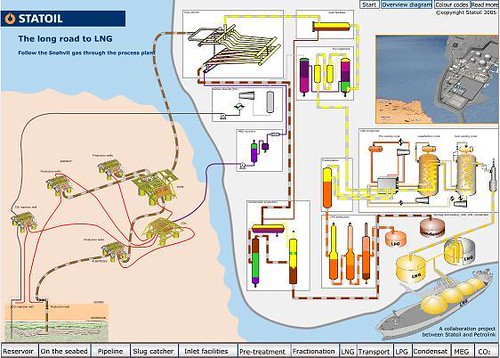
Above image shows a typical flow sheets for oil and gas exploration, Liquefied natural gas (LNG), Liquefied Petroleum Gas (LPG) and condensate production.
General units involved are Oil & gas exploration (sub-sea, top site, onshore), bulk separation, gas treatment prior to Natural Gas Liquid (NGL) extraction, Liquefied Petroleum Gas (LPG) fractionation, condensate stabilization, Carbon Dioxide (CO2) gas compression & reinjection, Mono-Ethylene glycol (MEG) regeneration, etc.
The following flash shows all above in a very simple manner. It is very useful to all engineers who just get involved in Oil & gas business. Click HERE for detail text.
Related Topics :
Labels: Acid Gas Removal, Fractionation, gas processing, Gas Sweethening, Refinery
Tuesday, September 4, 2007
Milt Beychok from www.air-dispersion.com has shared a schematic flow diagram of a typical GAS PROCESSING that depicts the various unit processes and the flow of intermediate product streams that occurs between the inlet Gas with associate condensate as feedstock and the final end products. This image has given a brief idea how gas/condensate goes through separation and purification. Products included Condensate, C2, C3, C4, Light gas (high C1), and side product elementary Sulfur.
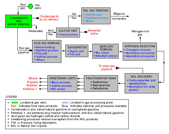
Click image to view original
Labels: Acid Gas Removal, gas processing, Gas Sweethening
