Sunday, August 12, 2012
LNG Industry is an unique quarterly magazine that covers the global LNG sector from start to finish, from liquefaction to regasification. Each issue provides :
- in-depth technical articles focusing on all aspects of the LNG sector
- quality keynote articles from LNG majors, financial institutions and industry commentators
- regular regional reports from Europe, North and South America, Africa, Asia and the Middle East
The Winter 2011 issue of LNG Industry has a particular focus on LNG safety and alternative uses of LNG apart from transportation, ranging from locomotive use to shipping fuel.

Winter 2011 issue covers following topics :
Picking up the pace
Terry Willis, The EIC, Dubai, examines the increasing pace of new LNG liquefaction capacity and exports from the Middle East.
Is anyone thinking about the weather?
Mark W. Jessup, Markey Machinery Co., USA, examines the world’s changing weather patterns and what LNG companies can do to prepare themselves for the worst.
LNG: the flexible element
James Patrick O’Brien, EGL AG, Switzerland, comments on LNG market developments and the future of LNG from a market participant’s perspective.
Is LNG on track?
Constantyn Gieskes, Braemar Wavespec USA, Inc., USA, describes the potential benefits and pitfalls of converting rail locomotives to run on LNG.
Gas fuel: a new generation
Reidar Strande, Hamworthy Plc., UK, discusses the benefits of an LNG fuelling system.
The missing link
Jürgen Harperscheidt, TGE Marine Gas Engineering, Germany, discusses the development of bunkering LNG for shipping uses.
Who’s in control?
Dr. Ian Synge, ShipNet AS, UK, discusses the growing use of enterprise software to transport LNG efficiently and safely.
Intelligent valves
Sari Aronen, Metso Automation Inc., Finland, explains the benefits of selecting the right valves for LNG processing applications.
Pressure relief
Roger Bours, Fike Europe, Belgium, addresses the use of pressure safety devices in cryogenic processes.
Time to switch?
Amin Almasi, WorleyParsons, Australia, examines the benefits of switching to new aero-derivative gas turbines over their heavy frame counterparts.
Sustainable insulation
Steve Oslica, Pittsburgh Corning, USA, examines the environmental credentials of cellular glass insulation.
Mercury removal
Vince Atma Row and Matthew Humphrys, Johnson Matthey, UK, examine the problem of mercury adsorption on gas plants and pipelines.
Subscript FREE LNG Industry here
Related Post
Labels: E-Doc, Education, Learning, LNG


Sunday, July 29, 2012
Recommended :
Sources :

Natural
gas is used in industry and household to provide heating energy. It is
explored from gas well, treated transported to customer via large and
long pipeline. It is become non-cost effective once the pipeline length
is exceeded 3000 - 3500 km. Thus, another mode of transportation,
Liquefied Natural Gas (LNG) is considered cost effective. Liquefied
Natural gas (LNG) is a process of cooling down the natural gas to form
liquid for easy storage and transportation. A LNG is normally contains
of Methane (CH4) which is more than 90% and other light hydrocarbon such
as Ethane (C2H6), Propane (C3H8), Butane (C4H10) and Nitrogen (N2)
inert gas. LNG is non-corrosive, non-toxic, non-carcinogenic, odorless
and colorless. However, it is flammable and explosive and create
greenhouse effect to environment.
Following is an simple development milestones for LNG since 19th century
| Year | Event | Remark |
| 19th Century |
Michael Faraday, a British Scientist liquefying various gases (including natural gas) in laboratory
| |
| 1873 | Karl Von Linde, a German engineer build 1st practical compressor refrigeration machine in Munich | |
| 1912 | 1st LNG plant is built in West Virginia | |
| 1914 | 1st (U.S.) patent awarded for LNG handling/shipping to Godfrey Cabot | |
| 1917 | Start operation of 1st LNG plant in West Virginia | |
| 1941 | 1st commercial LNG plant is built in Cleveland, Ohio | 2000 tpa |
| 1944 | At an LNG peak-shaving plant in Cleveland, an LNG storage tank with a low Nickel steel content (only 3.5%) fails. LNG spills into a sewer. Explosion within the sewer kills 128 people | |
| 1959 | World 1st LNG tanker "The Methane Pioneer", safely carries LNG from Lake Charles, LA., to Canvey Island, United Kingdom, initiating commercial LNG shipping. | 2000 tonnes LNG |
| 1960 | Conch International Methane conducts pioneering series of experiments involving small-scale LNG spills on land at Lake Charles, LA for U.S. Bureau of Mines. | |
| 1964 | 1st baseload LNG plant (CAMEL) in Algeria used Technip/Air Liquide's Cascade liquefaction process (three loops i.e. Propane, Ethylene & Methane) and Steam turbine to drive compressors The British Gas Council begins importing LNG from Algeria, making the United Kingdom the world's 1st LNG importer and Algeria as its first exporter. | 3-trains with capacity of 1 mtpa, located in in Arzew, Algeria |
| 1967 | National Fire Protection Association (NFPA) adopts its first LNG safety standards, NFPA 59A Standard for the Production, Storage, and Handling of LNG. | |
| 1969 | 1st LNG plant (Kenai, Alaska) used Phillips Cascade liquefaction technology and 1st to use gas turbine (single shaft) 1st LNG cargoes from Alaska to Japan (world largest LNG importer) | 1.5 mtpa in single train |
| 1970 | 1st LNG plant in Marsa El Brega, Libya used APCI's SMR liquefaction technology | 0.75 mtpa per trains |
| 1971 | Distrigas Corporation opens an LNG receiving and regasification terminal in Everett, MA. | |
| 1972 | 1st LNG baseload plant used APCI's C3MR liquefaction technology in BLNG 1st LNG plant used Technip 's Tealarc two pressure SMR technology in Skikda, Algeria 1st US federal LNG safety regulations adopted, incorporating NFPA 59A standards. | Skikda - 3 trains of 1 mtpa |
| 1986 | South Korea receives its 1st LNG shipment (from Indonesia). | |
| 1989 | 1st LNG plant (NWS) adopting Air-Cooling | |
| 1990 | Taiwan’s 1st LNG terminal receives a shipment from Indonesia. | |
| 1991 | 1st LNG deliveries from Australia’s North West Shelf (NWS) arrive in Japan and South Korea. | |
| 1995 | 1st LNG plant adopting Gas turbine GE Frame 6/7 | |
| 1999 | 1st LNG plant in West Hemisphere (Trinidad) | |
| 2000 | 1st peak shaving LNG plant in Pudong, Shanghai, China | |
| 2004 | The 1st offshore LNG terminal is approved, Port Pelican. Explosions and fire destroy a portion of the LNG liquefaction plant in Skikda, Algeria, killing 27 people. | |
| 2007 | 1st LNG plant use Linde's Multi Fluid Cascade Cycle (MFCC) technology (Snohvit, Norway) | 4.1 mtpa |
| 2009 | 1st LNG plant use Shell's DMR technology (Sakhalin, Russia) | 2 trains of 4.8 mtpa |
| 2011 | Qatar becomes world largest LNG exporter (using APCI's AP-X technology and gas turbine GE Frame 9E) | 6 trains of 7.8 mtpa |
| Dec 2016 | Petronas FLNG SATU - World 1st Mid scale FLNG (with N2 refrigeration cycle) comes on stream.(Kanowit gas field offshore Sarawak, Malaysia.) | 1.2 mtpa |
| March 2018 | Golar Hilli Episeyo FLNG, 1st FLNG (with PRICO SMR refrigeration process) converted from Moss LNG carrier, come on stream. (offshore Kribi in Cameroon) | 4 x 0.5 mtpa |
| March 2018 | Yamal LNG plant in Russian Arctic area in operation | 5.5 mtpa |
| 2018 | World 1st large FLNG expected to comes on stream | 3.6 mtpa |
3) "Next Generation Onshore LNG plant design", Marjan et.al
4) "Liquefaction Technology : Developments through History", Paul Bosma et.al.
5) "Shell and Petronas to race on Floating LNG"
4) "Liquefaction Technology : Developments through History", Paul Bosma et.al.
5) "Shell and Petronas to race on Floating LNG"
| Featured Resources: | |
 | LNG Industry Provides global coverage of the entire LNG value chain.... >> |
Labels: LNG
Sunday, December 11, 2011
Nowadays Smart phone has been commonly used by most engineers. A lot of handy application has been created to ease engineers like you for daily activities. Similarly DNV has created and released a "LNG Conversion Calculator" for Iphone user. It is FREE.

Above is snapshot of the DNV's LNG Conversion Calculator.
This LNG Conversion Calculator cover several important units :
You may easily download from Iphone's APP STORE. Read more information in ITune.- m3 NG
- ft3 NG
- tonnes oil eq
- tonnes LNG
- BTU
- barrels oil eq
- m3 LNG
Following are some typical results :
- 1 x 10⁶ tonnes LNG = 52 x 1012 BTU
- 1 x 10⁶ tonnes LNG = 8.68 x 10⁶ barrels oil eq
- 1 x 10⁶ tonnes LNG = 1.23 x 10⁶ tonnes oil eq
- 1 x 10⁶ tonnes LNG = 2255.822 x 103 m3 LNG
- 1 x 10⁶ tonnes LNG = 1.38 x 10⁹ m3 NG
- 1 x 10⁶ tonnes LNG = 48.7 x 109 ft3 NG
| Featured Resources: | |
 | LNG Industry Provides global coverage of the entire LNG value chain.... >> |
Comments :
- Exact conversion subjects to molecular weight. Above is only approximation.
- Finding shows above was based on "BP Statistical Review of US, Energy" as source.
- Present version is 1.1. Only cover mass-volume conversion. Wish develop can expand it to cover flowrate to ease users.
- There is no clear definition of volumetric flow at condition i.e. at Standard or Normal condition, etc.
Related Topics
Saturday, December 10, 2011
Liquefied Natural gas (LNG) contains of majority Methane (CH4) which is more than 90% and other light hydrocarbon such as Ethane (C2H6), Propane (C3H8), Butane (C4H10) and Nitrogen (N2) inert gas. LNG is non-corrosive, non-toxic, non-carcinogenic, odorless and colorless. However, it is flammable and explosive and create greenhouse effect to environment.
Component in natural gas potentially freeze and blocking cryogenic heat exchanger need to be reduced to level at or below it freezing point. The following table list out the solubility of several components in LNG :
Natural gas may contains of other contaminants such as Carbon Dioxide (CO2), Hydrogen Sulfide (H2S), Water (H2O), Mercury (Hg), Nitrogen (N2), Helium (He), Heavy Hydrocarbon, BTEX, CO2, S, etc. These component need to be extracted from natural gas to an acceptable, practical and economic level when it is liquefied and transported. The following are general reasons why these contaminants need to be extracted :
- solidify / freezing results cryogenic heat exchanger blockage (contaminants such as CO2, H2O, C5+, BTEX, etc)
- corrosion & cracking of cryogenic heat exchanger made of aluminum material (contaminant such as Hg)
- affecting product heating value (component such as N2, C2, C3, C4, etc)
- extraction highly valuable / important component (such as N2, He, etc)
- product toxicity (such as H2S, mercaptans i.e. methanethiol (CH3SH) and ethanethiol (C2H5SH), etc)
- stratification results roller (such as N2)
Component in natural gas potentially freeze and blocking cryogenic heat exchanger need to be reduced to level at or below it freezing point. The following table list out the solubility of several components in LNG :
| Component | Estimated Solubility Concentration (ppmV) | Practical Acceptable Concentration (ppmV) | Remark |
| n-C5 | 8,900 | 1,000 | |
| neo-C5 | - | 5 | |
| C6 | 217 | 150 | |
| C7 | 70 | 50 | |
| C8 | 0.5 | 0.5 | |
| C9 | 0.1 | 0.1 | |
| C10 | 0.000001 | 0 | |
| Cyclo-C6 | 115 | 100 | |
| M-Cyclo-C5 | 575 | 550 | |
| M-Cyclo-C6 | 335 | 300 | |
| Benzene | 1.53 | 0.5 | |
| Toluene / M-Benzene | 24.9 | 20 | |
| O-Xylene | 0.22 | 0.1 | |
| M-Xylene | 1.54 | 1.0 | |
| P-Xylene | 120 | 100 | |
| CO2 | 40 | 50 - 100 | Practical experience shown higher CO2 concentration is acceptable / practical. |
| H2O | 0.0001 | 1.0 | Practical experience shown higher H2O concentration is acceptable / practical. |
Corrosion & Cracking
Mercury (Hg) present in natural gas can cause corrosion & cracking of cryogenic heat exchanger made of aluminum material. Typically Hg concentration shall be limited to 0.01 microgram / Nm3.
| Featured Resources: | |
| LNG Industry Provides global coverage of the entire LNG value chain.... >> |
Stratification & Rollover
At LNG storage condition, Nitrogen will have lower dew point compare to Methane. Nitrogen in LNG tends to vaporize first compare to Methane. As Nitrogen is heavier than Methane, top layer of LNG tank would tends to rollover and generate excessive vapor which can cause overpressure and relieve BOG to atmosphere. Through experience, Nitrogen content in LNG is normally limited to maximum 1 mol%.
Toxicity
Present of H2S, COS and merceptants in LNG would results high toxicity LNG. The following list out typical level in LNG :
| Component | Practical Acceptable Concentration (ppmV) | Remark |
| H2S | 4 | |
| COS | 0.5 | |
| Total Sulfur | 10 - 200 | Subject to country |
| Merceptants Sulfur | 6 - 15 | Subject to country |
Above are typical value for quick reference. Figures may change according to LNG composition, liquefaction temperature, etc and will varies from case to case. Shall be used as reference only.
Related Topics
- Design of Compact Plate Fin Heat Exchanger
- Do not Under-estimate The Impact of Altitude Change
- Quick Way to Estimate Insulation for Cold Services
- Quick Way to Estimate BOG
- How Boil-Off-Gas (BOG) is Generated
- Techniques to Achieve Cryogenic Temperature
- PFHE & CWHE Comparison in LNG Plant
- LNG and Supply Chain
Labels: LNG
Wednesday, December 7, 2011
Plate fin heat exchangers (PFHE) is compact, low weight and high effectiveness are widely used in cryogenic applications. Normally PFHE is made of a stack of corrugated fins alternating with nearly equal number of flat separators known as parting sheets, bonded together to form a monolithic block. Feed and exit headers are welded to provide the necessary interface with the inlet and the exit streams. While aluminum is the most commonly used material, stainless steel construction is employed in high pressure and high temperature applications.

This following thesis "Design of Compact Plate Fin Heat Exchanger" by JAINENDER DEWATWAL is rather interesting for those who would like to have brief idea about PFHE and methodology for PFHE calculation. Several correlations such as MANGAHANIC, WIETING, JOSHI &WEB, DEEPAK & MAITY have been used in the calculation. For those who are new in PFHE design, this may be good source to start...
Related Post
- Brazed Aluminium Heat Exchanger (BAHX) Standard
- PFHE & CWHE Comparison in LNG Plant
- Control Around Heat Exchanger
- FAYF - Useful Heat Transfer Equation
- Few Tips on Energy Efficient & Recovery
- Heat Transfer - Internal and External Flow
- FREE E-book........A Heat Transfer Textbook
- Typical Heat Transfer Coefficient For Air-Cooled Heat Exchanger
Labels: Brazed Plate Heat Exchanger, Compact heat Exchanger, Heat Exchanger, LNG
Wednesday, October 6, 2010
Many LNG plants are built at the seaside to ease transportation, product loading and unloading. The atmospheric pressure with plant near seaside is 101325 Pa and all facilities are designed to the atmospheric pressure of 101325 Pa. However, if this plant is built in inland at high altitude, atmospheric pressure can seriously affect the design and operation of a LNG plant. Prior to discuss how the design and operation is impacted, lets step back to look at definition of pressure.
Operating pressure is commonly written as gauge pressure e.g. kPag, barg, etc in engineering whilst absolute pressure e.g kPaa, bara, etc. Absolute pressure equal to gauge pressure plus atmospheric pressure.
Example :
5 bar abs = 5 barg + 1.01325 bar = 6.01325 bara
The standard atmosphere pressure is pressure defined as being equal to 101,325 Pa or 101.325 kPa and normally refer to mean sea level (h=0 m). Atmospheric pressure is decreased with altitude (elevation from mean sea level or earth surface) with following relation.

Pb = Static pressure (Pa)
Tb = Standard temperature (K)
Lb = Standard temperature lapse rate -0.0065 (K/m) in ISA
h = Height above sea level (meters)
hb = Height at bottom of layer b (meters; e.g., h1 = 11,000 meters)
R = Universal gas constant for air: 8.31432 N.m /(mol.K)
g0 = Gravitational acceleration (9.80665 m/s2)
M = Molar mass of Earth's air (0.0289644 kg/mol)
Altitude = 0 – 11000m, Tb = 288.15 K, Lb = -0.0065 K/m, Pb = 101325 Pa
Altitude = 11000 – 20000m, Tb = 216.65 K, Lb = -1 x 10E-30 K/m, Pb = 22632.1 Pa
Altitude = 20000 – 32000m, Tb = 216.65 K, Lb = 0.001 K/m, Pb = 5474.89 Pa
By inclusion of specific parameters, for altitude = 0 – 11000m, atmospheric pressure is

Example
At altitude of 500m above mean sea level, atmospheric pressure is approximately 95460.84 Pa.
At altitude of 1000m above mean sea level, atmospheric pressure is approximately 89874.57 Pa.
How altitude impacting LNG production rate ?
Let compare LNG production rate change with a plant built at seaside (h = 0) and another LNG plant built at a site with altitude of 1000m. For both plant, LNG store at same gauge pressure (e.g. 50 mbarg), same LNG rundown temperature (e.g. -163 degC), same LNG tank dimension with same in-leak heat (normally higher altitude is with lower ambient temperature, lower in-leak heat is expected. However, the impact is negligible).
LNG from Main Cryogenic Heat Exchanger (MCHE) outlet is set at 50 barg and negative 164.8 degC. A JT valve is letting down pressure to LNG storage tank operating pressure of 50 mbarg. MCHE outlet mass flow set at 50000 kg/h. LNG is pure Methane (C1). Assumed same in-leak heat of 300 kW.
Case : Seaside
Altitude, h = 0m
Atmospheric pressure = 101.325 kPa abs
LNG operating pressure = 50 mbarg = 5 + 101.325 kPa abs = 106.325 kPa abs
From simulation (see below image), BOG flow = 1374 kg/h,
LNG production rate = 48626 kg/h

Case : Inland
Altitude, h = 1000m
Atmospheric pressure = 101325 (1 - 2.25577E-05 x 1000)^5.25588 = 89.8746 kPa abs
LNG operating pressure = 50 mbarg = 5 + 89.8746 kPa abs = 94.8746 kPa abs
From simulation (see below image), BOG flow = 1863 kg/h,
LNG production rate = 48137 kg/h

Same facilities and operating condition, the LNG production in Inland (at 1000m) reduced by 1%.
How altitude impacting Air Compressor / Blower power requirement ?
Air compressor at seaside is sucking air at atmospheric pressure of 101.325 kPa abs. If this air compressor is located at altitude of 1000m, air compressor is sucking air at atmospheric pressure of 89.8746 kPa abs. With same discharge pressure, higher head is expected at high altitude and higher power is required. Normally the head is rather large for air compressor, therefore the additional power may not be so significant. However, it could be significant for an air blower sent air to process with fix pressure. One shall remember, it may have no significant impact to an air blower sucking air from atmosphere and discharging air to atmosphere again.
Concluding Remark
Atmospheric pressure change with altitude and this will have impacts to facilities design. Do not under-estimate this impact.
Labels: LNG
Wednesday, September 29, 2010
Earlier post "How Boil-Off-Gas (BOG) is Generated" and "Quick Way to Estimate BOG" discussed several ways result Boil-Off-Gas (BOG) generation and simple way to estimate BOG. Heat leak into piping wrapped with Cold insulation is one of the way possibly result significant BOG generation, in particular in large base load plant where product is loaded into ship. Long rundown and loading line from production plant and from storage tank to ship can generate significant BOG. Proper selection and determination of insulation thickness can minimize BOG generation economically.
Overall heat transfer cooefficient estimate from Nusselt number :


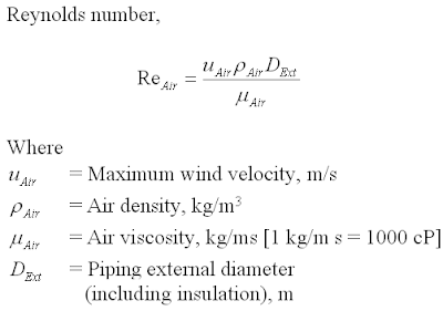
Piping in-leak heat can be estimated with following equation
 with heat flux

Piping external diameter = 152.4 mm
Piping length = 100 m
Insulation material = Polyisocyanurate
Insulation thermal conductivity = 0.023 W/mK
Assumed Insulation thickness = 60 mm
Piping external diameter (including insulation) = 152.4 + 2x60 = 272.4mm
Air :
Air Velocity = 5 m/s
Air Thermal Conductivity = 0.029 W/mK
Air specific heat = 1009 J/kgK
Air density = 1.038 kg/m3
Air viscosity = 0.02 cP
Calculation :
Air Prandtle Number = 0.6959
Air Reynolds Number =70687.8
Overall Heat transfer Coefficienct = 18.096 W/m2K
Piping In-leak heat = 2125.72 W
Piping surface area = 85.58 m2
Average heat flux = 24.8 W/mK < 25 W/mK...OK
Similar calculation applied to 1" to 28"
1" - 50mm insulation thickness
2" - 50mm insulation thickness
3" - 60mm insulation thickness
4" - 60mm insulation thickness
6" - 60mm insulation thickness
8" - 70mm insulation thickness
10" - 70mm insulation thickness
12" - 70mm insulation thickness
16" - 70mm insulation thickness
20" - 70mm insulation thickness
24" - 70mm insulation thickness
28" - 70mm insulation thickness
Key Rule
Rule of thumb for economic heat flux for heat in-leaks range from 25 to 35 W/m2. This is the key rule to derive an economic insulation for cold service whilst minimizing BOG generation.Recommended :
- Subscribes to FREE Hydrocarbon Processing
- Tips on Succession in FREE Subscription
 Insulation Material & Thermal Conductivity
Common insulation material used in cold services (sometime called cryogenic service in extremely low temperature case e.g. LNG with operating temperature of approximately -162 degC) are typically Polyurethane and Polyisocyanurate Foam (PIR). These insulation material have very low conductivity minimizing heat from ambient entering cold fluid. Typical thermal conductivity for these material is approximately 0.023 W/mK @ 20 degC.- Subscribes to FREE Hydrocarbon Processing
- Tips on Succession in FREE Subscription
Insulation Material & Thermal ConductivityInsulated Piping In-Leak Heat
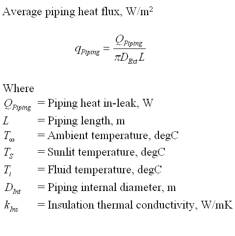
Estimation of piping in-leak heat from ambient starts with estimation of heat transfer coefficient using Nusselt number which is a function of Prandtle and Reynolds number.Overall heat transfer cooefficient estimate from Nusselt number :

where Prandtle number

and Reynolds number

Piping in-leak heat can be estimated with following equation

Case study
Piping nominal size = 6"Piping external diameter = 152.4 mm
Piping length = 100 m
Insulation material = Polyisocyanurate
Insulation thermal conductivity = 0.023 W/mK
Assumed Insulation thickness = 60 mm
Piping external diameter (including insulation) = 152.4 + 2x60 = 272.4mm
Air :
Air Velocity = 5 m/s
Air Thermal Conductivity = 0.029 W/mK
Air specific heat = 1009 J/kgK
Air density = 1.038 kg/m3
Air viscosity = 0.02 cP
Calculation :
Air Prandtle Number = 0.6959
Air Reynolds Number =70687.8
Overall Heat transfer Coefficienct = 18.096 W/m2K
Piping In-leak heat = 2125.72 W
Piping surface area = 85.58 m2
Average heat flux = 24.8 W/mK < 25 W/mK...OK
Similar calculation applied to 1" to 28"
1" - 50mm insulation thickness
2" - 50mm insulation thickness
3" - 60mm insulation thickness
4" - 60mm insulation thickness
6" - 60mm insulation thickness
8" - 70mm insulation thickness
10" - 70mm insulation thickness
12" - 70mm insulation thickness
16" - 70mm insulation thickness
20" - 70mm insulation thickness
24" - 70mm insulation thickness
28" - 70mm insulation thickness
Labels: gas processing, LNG
Sunday, August 29, 2010
Earlier post "How Boil-Off-Gas (BOG) is Generated" has discussed several ways can result Boil-Off-Gas generation. They are listed below :
- vaporized vapor due to barometric pressure decrease
- vaporized vapor due to ambient temperature increase
- cryogenic fluid rundown piping
- cryogenic fluid circulation / loading line
- ship / truck loading arm
- cryogenic fluid storage tank
- cryogenic fluid rundown pump
- cryogenic fluid in-tank pump
- flashed non-condensable gasses
- negative Joule-Thompson effect
- "hot" rundown cryogenic liquid into "cold" cryogenic liquid
- cooling of loading arm
- cooling of ship / truck
This post will discuss quick way to estimate BOG flow.
Recommended :
- Subscribes to FREE Hydrocarbon Processing
- Tips on Succession in FREE Subscription
Atmospheric pressure at sea level is 101.325 kPa abs. Atmospheric pressure is reduced with increase in altitude. For example, at elevation of 1,000 meter, the atmospheric pressure can be as low as 89.81 kPa abs. Cryogenic storage may be designed to operate between 50-70 mbar gauge. If the cryogenic storage tank is at beach (sea level), the operating pressure in the tank is approximately 106.325 - 108.325 kPa abs. If this cryogenic storage is at 1,000 meter, the operating pressure in the tank is approximately 94.81 - 96.81 kPa abs. Lower operating pressure in tank can results higher vaporization and more BOG is generated. Therefore, it is always a good practice to use absolute pressure whenever dealing with cryogenic storage tank. Correct pressure modeling in process simulator is extremely important in finding quantity of BOG generated.
Heat leaks into cryogenic fluid can be via rundown / circulation piping, loading arm & storage tank. Proper selection, installation and maintenance of insulation is one of the key factor in minimizing heat leaks into cryogenic system, hence BOG generation. Besides insulation, other external factors such as wind speed, solar radiation, ambient temperature, sand conductivity and etc, affect heat leak. However, these factors are hard to be managed. Heat leaks into system can be calculated by considering heat conduction, convection and radiation. However, this type calculation involve a lot of uncertainties, assumption and rather complicated. Based on past experiences, an approximate method using vaporization coefficient in determining BOG generation due to heat leaks via storage tank, may be considered during conceptual phase.

Vaporization coefficient (k) may range from 0.04% to 0.06% for LNG whilst 0.06% to 0.1% for Propane, Butane and LPG. One may take note that above are typical for large storage tank e.g. 160,000m3. Higher k factor should be used for smaller storage. For example, 60,000m3, k of 0.08 - 0.1% may be considered.
Above equation is applicable to storage tank which is low surface area-to-volume ratio. However, piping with very low volume and high surface area may experience higher heat input comparatively. Following equation may be used to estimate BOG generated due to piping.
 Average heat flux subject to piping diameter. In general, kp of 25 -35 W/m2 may be considered.
Energy is transferred to pump to move quantity of liquid. Part of the energy will loss due to deficiency. and results BOG generation. Following equation may be considered to estimate BOG generated due to pump deficiency.

Pump efficiency can be range from 55% - 75% for common centrifugal pump.
Cryogenic liquid produced from main plant and transfer to cryogenic liquid storage tank. Inflow liquid will displaced vapor and add-on to BOG generation. Following equation may be used.

Other factors result generation of flashed vapor or BOG generation such as present of non-condensable gasses, negative Joule-Thompson effect and "hot" rundown cryogenic liquid into "cold" cryogenic liquid, will possibly be modeled in process simulator.
Cooling of loading arm and tank in ship / truck may generate substantial amount of vapor initially and reduce as loading arm and tank is cooled. This BOG generation may required dynamic simulation which will not be presented in this post.
- Subscribes to FREE Hydrocarbon Processing
- Tips on Succession in FREE Subscription
Atmospheric pressure at sea level is 101.325 kPa abs. Atmospheric pressure is reduced with increase in altitude. For example, at elevation of 1,000 meter, the atmospheric pressure can be as low as 89.81 kPa abs. Cryogenic storage may be designed to operate between 50-70 mbar gauge. If the cryogenic storage tank is at beach (sea level), the operating pressure in the tank is approximately 106.325 - 108.325 kPa abs. If this cryogenic storage is at 1,000 meter, the operating pressure in the tank is approximately 94.81 - 96.81 kPa abs. Lower operating pressure in tank can results higher vaporization and more BOG is generated. Therefore, it is always a good practice to use absolute pressure whenever dealing with cryogenic storage tank. Correct pressure modeling in process simulator is extremely important in finding quantity of BOG generated.Heat leaks into cryogenic fluid can be via rundown / circulation piping, loading arm & storage tank. Proper selection, installation and maintenance of insulation is one of the key factor in minimizing heat leaks into cryogenic system, hence BOG generation. Besides insulation, other external factors such as wind speed, solar radiation, ambient temperature, sand conductivity and etc, affect heat leak. However, these factors are hard to be managed. Heat leaks into system can be calculated by considering heat conduction, convection and radiation. However, this type calculation involve a lot of uncertainties, assumption and rather complicated. Based on past experiences, an approximate method using vaporization coefficient in determining BOG generation due to heat leaks via storage tank, may be considered during conceptual phase.

Vaporization coefficient (k) may range from 0.04% to 0.06% for LNG whilst 0.06% to 0.1% for Propane, Butane and LPG. One may take note that above are typical for large storage tank e.g. 160,000m3. Higher k factor should be used for smaller storage. For example, 60,000m3, k of 0.08 - 0.1% may be considered.
Above equation is applicable to storage tank which is low surface area-to-volume ratio. However, piping with very low volume and high surface area may experience higher heat input comparatively. Following equation may be used to estimate BOG generated due to piping.

Energy is transferred to pump to move quantity of liquid. Part of the energy will loss due to deficiency. and results BOG generation. Following equation may be considered to estimate BOG generated due to pump deficiency.

Pump efficiency can be range from 55% - 75% for common centrifugal pump.
Cryogenic liquid produced from main plant and transfer to cryogenic liquid storage tank. Inflow liquid will displaced vapor and add-on to BOG generation. Following equation may be used.

Other factors result generation of flashed vapor or BOG generation such as present of non-condensable gasses, negative Joule-Thompson effect and "hot" rundown cryogenic liquid into "cold" cryogenic liquid, will possibly be modeled in process simulator.
Cooling of loading arm and tank in ship / truck may generate substantial amount of vapor initially and reduce as loading arm and tank is cooled. This BOG generation may required dynamic simulation which will not be presented in this post.
Related Topics
- How Boil-Off-Gas (BOG) is Generated
- Techniques to Achieve Cryogenic Temperature
- PFHE & CWHE Comparison in LNG Plant
- LNG and Supply Chain
- Gas Processing, NGL Extraction & LPG Fractionation
- Typical Gas Processing Flow Scheme
- Typical Refinery Flow Scheme
- Floating Gas Refinery Unit
- Use Wobbe Index to Manage Fuel Quality to Gas Burner
Labels: gas processing, LNG
Monday, August 23, 2010
Recommended :
- Subscribes to FREE Hydrocarbon Processing
- Tips on Succession in FREE Subscription
Liquefied Petroleum Gas (LPG) contains mainly Propane (C3) and Butane (i-C4 & n-C4), Liquid Ethylene (C2=) and Liquefied Natural Gas (LNG) contains mainly Methane will evaporate at ambient condition e.g. 20 degC @ 101.325 kPag.
LPG, Liquid Ethylene and LNG can be stored in refrigerated vessel at its bubble point and atmospheric pressure. Their bubble point can be as low as -40, -104 and -162 degC are commonly known as cryogenic temperature and fluid as cryogenic fluid.
- Subscribes to FREE Hydrocarbon Processing
- Tips on Succession in FREE Subscription
Liquefied Petroleum Gas (LPG) contains mainly Propane (C3) and Butane (i-C4 & n-C4), Liquid Ethylene (C2=) and Liquefied Natural Gas (LNG) contains mainly Methane will evaporate at ambient condition e.g. 20 degC @ 101.325 kPag.LPG, Liquid Ethylene and LNG can be stored in refrigerated vessel at its bubble point and atmospheric pressure. Their bubble point can be as low as -40, -104 and -162 degC are commonly known as cryogenic temperature and fluid as cryogenic fluid.
Heat leaks into the cryogenic fluid will results vaporization and lead to Boil-Off-Gas (BOG) generation. Other than heat leak, there are other scenarios can lead to BOG generation :
- vaporized vapor due to barometric pressure decrease
- vaporized vapor due to ambient temperature increase
- cryogenic fluid rundown piping
- cryogenic fluid circulation / loading line
- ship / truck loading arm
- cryogenic fluid storage tank
- cryogenic fluid rundown pump
- cryogenic fluid in-tank pump
- flashed non-condensable gasses
- negative Joule-Thompson effect
- "hot" rundown LNG into "cold" LNG
- cooling of loading arm
- cooling of ship / truck
Vaporized vapor due to barometric pressure decrease & ambient temperature increase
Environment pressure and temperature change affects BOG generation. Maximum BOG generation during summer, noon and high elevation (with low barometric pressure). On the other hand, minimum BOG generation during winter, mid-night and near sea side (high barometric pressure).
Heat leaks into Cryogenic fluid rundown piping, circulation / loading line, ship / truck loading arm & storage tank
Ambient heat leaks cryogenic fluid will be limited by insulation layer. Heat leaks into subjects to insulation thickness, thermal conductivity, installation quality, etc. Higher insulation thickness, lower thermal conductivity, high installation quality and etc maintain good heat insulation and reduce BOG generation.
Heat generated by rundown pump & in-tank pumpand leaks into Cryogenic fluid
Pumps is required for transferring cryogenic liquid from production plant to storage tank and from storage tank to ship/truck. Pump will absorb power to move cryogenic fluid and any deficiency will generate heat and it will transfer into cryogenic fluid. Pump heat leaks subject to pump capacity, develop head and efficiency. Larger pump, higher head and lower efficiency lead to excess heat generation and leaks into cryogenic fluid.
Flashing of non-condensable gasses
Present of inert / non-condensable gasses such as nitrogen, carbon monoxide in cryogenic fluid may flash in the storage tank.
Negative Joule-Thompson effect
Another phenomenon is negative Joule Thompson (negative JT) where pressure decrease in rundown line lead to higher temperature. Typical gas is Hydrogen.
"Hot" rundown into "cold" cryogenic fluid
Hot cryogenic fluid from one train with hotter temperature which carries heat and rundown into cryogenic tank with colder temperature can results vaporization.
Hot cryogenic fluid from one train with hotter temperature which carries heat and rundown into cryogenic tank with colder temperature can results vaporization.
Cooling of loading arm & tank in ship / truck
Loading arm is heated to ambient temperature when it is unrest for long time. Cryogenic tank in ship / truck is heated by ambient when it is returned with empty tank. All loading arm and tank in ship/truck will needs cooling prior to storage. Large amount of BOG is generated during cooling time.Coming topic will discuss quick way to estimate BOG rate.
Related Topics
Labels: gas processing, LNG
Sunday, August 8, 2010

Georges Claude, in 1902 produced a piston expansion engine working at the low temperatures required for the liquefaction of air. The increase in cooling effect over the Joule-Thomson nozzle expansion of the Linde-Hampson designs. The expansion through an expansion valve is an irreversible process. energy is removed from the gas stream by allowing it to do some work in an expansion engine or expander.

Recommended :
The process is based on a suitable modified Claude cycle which minimizes the umber of heat exchangers and also takes care to accommodate the in house developed turbo xpander. The process design is carried out using the standard calculation procedure and is validated by using process simulation software, Aspen Hysys. parametric analysis is carried out to access the role of different component efficiencies in predicting overall system efficiency at the design and off design conditions. In this analysis, the available turbo expander efficiency is considered to evaluate the feasible heat exchanger efficiency in order to optimize the plant efficiency. The thermodynamic parameters (temperature, pressure, pinch point temperature) are evaluated to obtain the optimum mass fraction through turbo expander for maximum liquid yield. This investigation not only gives the analysis of nitrogen liquefier, but also it will act as a basic frame work for any liquefier and helium liquefier in particular as a future mission.
Download
Related Topics
Labels: gas processing, LNG
Sunday, July 11, 2010
Main Cryogenic heat exchanger (MCHE) is one of key equipment in natural gas liquefaction (LNG) plant. MCHE used in liquefaction of natural gas having some special characteristic :
- Intensive/excessive heat exchange (230 - 400 kW / ton LNG)
- Complex heat transfer - Heat transfer from one (or several) very high pressure natural gas stream to one or several low pressure refrigerant streams
- Thermal stress/shock - Very large temperature difference between inlet (40 degC) and outlet temperature (-162 degC)
- Operate at very low temperature (-162 degC)
- High heat transfer efficiency - Very low temperature approach (2-3 degC) to maximize heat transfer per unit area
- Involve phase change and risk of phase separation and proper distribution
- High risk of leakage and safety related issue
- High risk of blockage/plugging
- Lightweight & easy transportation
Two type of compact MCHE widely used in LNG plant. There are Plate-Fin Heat Exchanger and Coil (Spiral) Wound Heat Exchanger. Below images are typical CWHE and PFHE.
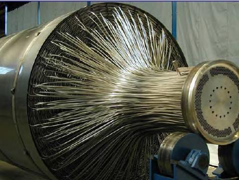
CWHE
CWHE is coils/tubes wound in spiral around a mandrel and all coils / tubes are contains within a pressure vessel. Multiple coils/tube in bundle can be flew simultaneously within the pressure vessel.

PFHE
PFHE is corrugated or serrated plate stacking on each and others to creates cross and/or counter flow paths to allow heat transfer of multiple fluids.
Although both type of HE have been widely used, CWHE and PFHE have their own special features and advantages. Below are simple comparison between both CWHE and PFHE.
| Features | Coil Wound Heat Exchanger (CWHE) | Plate-Fin Heat Exchanger (PFHE) |
| Compactness | Compact | Extremely compact |
| Heat Transfer area (m²/m³) | 20 - 300 | 300 - 1400 |
| Flow type in heat transfer | Cross-Counter | Cross and/or Counter |
| Flow pattern | Single and/or two phases | Single and/or two phases |
| Flow streams | Single or Multiple | Single or Multiple |
| Configuration | Single or multiple coil-in-vessel unit | Multiple plate-fin units |
| Flow path | 8-12mm tube | 1-2 mm flow channel |
| Risk of contaminant built-up | Less (smooth tube surface) | More (multiple channels / cores increase crevices) |
| Risk of Plugging | Lower | Higher |
| Thermal Stress Resistance | Higher (tube robustness & flexibility) | Lower (plate fin inflexible) |
| Risk of Thermal Stress | Lower | Higher |
| Gas/Liquid distribution | Less mal-distribution (single flow channel) | Higher mal-distribution (multiple unit in parallel) |
| Risk of Thermal Shock | Lower | Higher (mal-distribution lead to imbalance heat transfer) |
| Safety | Lower (tube contains within pressurized vessel - natural gas leaks to vessel) | Higher (natural gas leaks to atmosphere) |
| Availability | Higher (production continue with some tube leaks until next shutdown) | Lower (immediate production shutdown when leaks occur) |
| Transportation | Reasonable easy (with multiple bundles) | Easy (Multiple units) |
| Material | Aluminum / Stainless Steel / Carbon Steel / Others Alloy | Aluminum |
| Cost | Higher | Lower |
Related Post
- Control Around Heat Exchanger
- FAYF - Useful Heat Transfer Equation
- Few Tips on Energy Efficient & Recovery
- Heat Transfer - Internal and External Flow
- FREE E-book........A Heat Transfer Textbook
- Typical Heat Transfer Coefficient For Air-Cooled Heat
- COLLECTION of Typical Overall Heat Transfer
- COLLECTION of Fouling Factor (FF) use in Heat Exchanger Design
Labels: Brazed Plate Heat Exchanger, Compact heat Exchanger, Heat Exchanger, LNG
Friday, December 25, 2009
Recommended :
Natural gas is known as one of the world’s cleanest fossil fuel and it burns to form Carbon Dioxide (CO2) and Water (H2O) without or with minimal smoke subject to composition. Increased world crude demand and price has slowly pushing energy consumers shift from conventional crude based fuel i.e. gasoline, kerosene, etc to natural gas based fuel i.e. liquefied natural gas (LNG), liquefied petroleum gas (LPG), Gas-to-liquid (GTL), etc.
Natural gas conventionally is distributed in gas network. Distribution by gas network will only feasible and cost effective in limited distance i.e. 3000-3500 km. Natural gas may be compressed and stored in very high pressure storage tank. However, high capital cost in high pressure storage tank and high safety risk has driven users look for better transportation and storage option. Liquefying natural gas is one of the option can be most feasible and cost effective. Natural gas in the form of LNG,cooled to minus 160-163 degree Celcius at atmospheric pressure, approximate 600 times smaller than its gaseous state, make it so cost effective in storage and long distance transportation.
In recent net search, there are number of LNG related video clips available in educating, promoting and awareness creation about LNG.
Researchers at Idaho National Laboratory have developed a small-scale Liquid Natural Gas systems to expand the use of clean fuel at an affordable cost.
Pulse of the Port details a proposal for a Liquified Natural Gas Plant at the Port of Long Beach.
One of the largest gas field in the world is located in the sea between Qatar and Iran. Qatar is expanding its fleet of ships to deliver liquified natural gas (LNG) to world market.
BP LNG Tangguh
Terminal operated by Terminale LNG Adriatico Srl, a company owned by Qatar Terminal Limited (45%), ExxonMobil Italiana Gas (45%) and Edison (10%), will be the first offshore facility in the world for unloading, storing and regasifying natural gas. This facility will thus play a key role in increasing Italys energy security and will make the Italian natural gas market more competitive.
The world's largest oil and gas project Sakhalin-2 has begun to produce LNG for the world market. Russia's first LNG cargo will be delivered to Japan.
Second LNG tanker for the Sakhalin-2 field
Labels: gas processing, LNG
