Monday, December 31, 2007

Sunday, December 30, 2007
According to US DOE, pumps are the second most widely used machines in the world, consume about 20% of the world's energy and possibly form 50% of a plant's energy cost. Many companies still take it easy and design & purchase pumping systems based on initial cost, without considering life cycle cost. Thus, Hydraulic Institute (HI) has taken an proactive initiative that educate how plants can increase efficiency and keep the energy low. It is called Pump Systems Matter (PSM). Read more HERE.

PSIM capabilities include :
- System hydraulic calculations
- Centrifugal & Positive Displacement pumps
- Pump efficiency and BEP evaluation
- Variable speed pumps
- Flow & pressure control values
- Impeller trimming
- Automatic pump curve viscosity corrections
- NPSH calculations
My 2-cents of thought...
Pumping system CAPEX is rather low compare to other equipments e.g. Reactor, Compressor, etc, thus less attention has been given to pumping system. Knowing pumping system is account for 50% of plant energy cost, OPEX is getting very important. The design and equipment selection strategy should be changed to Pumping system Life Cycle Cost consideration.
Knowing the important of LCC, management should pay extra emphasis in LCC and make it a policy and philosophy during initial design phase.
PSIM tool may be used in earlier design stage and updated from basic design to detailed design phase, last handover the model to operator for further optimization.
Related ArticlesPSIM tool may be used in earlier design stage and updated from basic design to detailed design phase, last handover the model to operator for further optimization.
- The Time Has Come: Pump Systems Do Matter
- Hydraulic Design Of Liquid with Pump Circuit - A revision kit...
- Hydraulic Design of Liquid Piping Systems - A revision kit...
- Why bypass Non-Return Valve (NRV) ?
Wednesday, December 26, 2007
A few phenomena in Restriction orifice (RO) has been discussed earlier in "A refresh to Process Engineer on few phenomena in restriction orifice". Even though RO is just to limit the flow passing across but it has been used in many application in different manners.
Minimize Gas/Liquid blowby Rate to Downstream Equipment
This common apply in High pressure and low pressure interface e.g. liquid drain from high pressure vessel to low pressure vessel. A liquid control valve (LCV) is maintaining the level. A RO is provided downstream of the LCV. During normal operation, the flow passing the the LCV and RO is small and RO has minimum impact to operation of LCV. In the event, level controller failure caused LCV FULL open, large amount of liquid follow by gas blowby will pass through the LCV and RO will limit to flow rate and pressure relief load of downstream system.
Avoid large amount liquid overload downstream vessel
Similar to above condition but the context here is to limit liquid flow to downstream equipment and to buy time for operator intervention.
Minimize Reboiling Load And Relieving Load
One of the application is to limit the heating medium flow into reboiler in the event of heating medium control valve failed on full open position. RO possibly limiting vapor generation rate and relief load of PRV on the associated column.
Centrifugal Pump Minimum Flow Protection
Centrifugal pump will experience cavitation at flow lower than allowance minimum flow of the pump. To avoid pump cavitation, a permanent recycle line with a restriction orifice with opening size for minimum flow of the pump will be installed at pump discharge.
Reduce Vent and Flare capacity
The inventory of an Oil and gas facilities shall be evacuated to a safe level within a limited time (i,e 15 minutes per APi Std 521). Thus, automatic blowdown system is provided to depressure the system. A restriction orifice provided downstream of blowdown valve (BDV) will limit the flow in to header and flare system but within the allowable time limit. The limited flow rate will avoid choked flow in the flare subheader/header and this will significantly reduce vent and flare load and ultimately CAPEX of waste disposal system.
Vent and Flare Purging
Vent and Flare header shall be kept at positive pressure to avoid air ingress into the vent and flare system. Inert gas or fuel gas purging is used to purge and maintain possitive pressure. A RO will be used to provided constant flow.
Equipment Protection via Controlled Blowdown
This application is quite similar to pump minimum flow protection but it normally apply in vapor system like compressor, Mole sieve bed, etc. Similar to automatic emergency blowdown system, compressor and mole sieve shall be depressured within safe time limit. Howver, large blowdown rate potentially damage the compressor seal and fluidization of mole sieve bed. Thus, the blowdown rate shall be limited to avoid occurrence of above events. RO is commonly apply.
Pump Seal Cooling
Pump seal shall be cooled either by the process itself or external cooling medium such as demineralizeds water, service water, etc. A Ro is common provided at the feeding line to ensure constant cooling medium supply for pump seal cooling
Above are simple listing of application of restriction orifice in different manner. There may be more applications in different plant. Why not share yours with us here ?
Update : May 09, 2009
Related Post
Labels: Depressurization, Hydraulic
Tuesday, December 25, 2007

I have HYSYS version 3.2, 2004 and 2006 installed in my PC. All using network token system and works well all the while. Recently i encountered "Failed to locate License" error in my PC. This is common and expected as all token that your company subscribed already used by other users.
This problem happened for next few time i tried to use HYSYS, even during non-peak time. I started to suspect some problem with my own PC. Initially we suspected there may be one or more HYSYS file corrupted and our first effort is reinstall HYSYS again. Nevertheless this remedy failed to remove the error and similar problem occurred again. We have rechecked all system again and also failed to remove the error. We have rechecked the installation manual and HYSYS support but all efforts failed.
We have spent a lot of time by tackling HYSYS and our focus is on HYSYS because the problem is with HYSYS. All in certain...an idea across our mind...should this problem cause by other software instead of HYSYS itself ?
Just refresh my mind and recall what i have done last week...i remembered that i have installed the SHELL FRED version 5 into my PC last week. We uninstalled the SHELL FRED version 5 and surprisingly the HSYSY works well after the removal of FRED. Obviously there is conflict between HYSYS and FRED.
I am not a Computer system engineer and removing this type of conflict is totally out of my knowledge. Our computer system engineer has been engaged to helps out on this issue. But i believe the Computer system engineer may not remove the conflict without my input.
Lesson learned
- There is a conflict between HYSYS and FRED. Installation of FRED after HYSYS will results HYSYS failed to locate the license file.
- Keep track of activities and performance of your PC for ease of troubleshooting in future
- Simple input and piece of information may the source of major problem. Do not ignore.
- Direction of solving a problem is very important. Missed direction will cost you million.
Related Post
- Bug in ASPENTECH HYSYS 2006 Dynamic Depressuring Fisher Valve model
- Controlled and Non-controlled Type Depressuring
- How to apply valve equation in HYSYS Depressuring ?
- Simulate Trayed & Packed bed column in HYSYS
- Correct model and thermo package in Amine system simulation using HYSYS
- How to differentiate MASS lower heating value and Volumetric Lower heating value (gas) in HYSYS ?
Labels: HYSYS
Monday, December 24, 2007
 Year 2008 is around the corner...Warm wishes from JoeWong...May new year bring you prosperous, health and wealth...
Labels: General
Sunday, December 23, 2007

HAVE YOU RENEWED YOUR REGISTRATION AS PROFESSIONAL ENGINEER ?
Year 2008 is around the corner and it signify that time to renew your registration of Professional Engineer for year 2008.
For those who registered as PE in BEM, you shall submit the following documents (minimum) for the renewal :
- Filled form "H"
- Summary of Continuous Professional Development (CPD) 2007 (minimum 50 hours per year)
- Check/bank draft / postal order/ money order payable to "Lembaga Jurutera Malaysia" OR pay online via Maybank2U (Click)
- Photo (for those have not submitted to BEM)
One shall remember, the last date of registration is 31st Jan 2008 and the payment is RM200 (below 60) and RM100 (above 60). Renewal after 31st Jan 2008 will be penalized with additional payment (RM500).
You may pay in other currency following number stated in circular...
Related Post
Friday, December 21, 2007
Restriction orifice is widely used to in Oil and Gas, Refinery and Petrochemical chemical plant. Make a simple search on internet, you may find plenty of articles related to functionality, calculation and specification of restriction orifice. The intention in this post is not to repeat what others has discussed in details but as a refresher to those who already knew about it and inform those who still unclear or misunderstood about restriction orifice.
What is restriction orifice ?
I have asked above question to young engineer with 2-3 years experience. The answer given by some of them were ”To reduce pressure drop like control valve but with fixed opening”. It sounded correct. Fluid passing restriction orifice with fixed opening and involve pressure drop across it. In my opinion, this is a misconception on functionality. Restriction orifice is used to limit flow to required or expected flowrate with the available differential pressure across.
How restriction orifice works ?
A fluid passing a fixed opening in restriction orifice, the fluid streamline will converge and squeeze through the opening. As it pass the opening, the momentum will keep it continue converge for short distance and diverge as the momentum is lost. The smallest cross sectional area between convergence and divergence is the well known vena contracta (VC). The velocity at VC is at maximum due to minimum cross sectional area for flow. Base on Bernoulli theorem, the pressure at VC is lowest.

As fluid passing the restriction orifice, converging towards vena contracta and diverge once it pass VC results two observations. Velocity is increased till maximum at VC and decreased after it passed VC. On the other hand, pressure is decreased till minimum at VC and increased to downstream pressure (backpressure). The increased pressure from VC is called pressure recovery.
NON-Choked flow vs Choked Flow
When the differential pressure (dP) between restriction orifice upstream and downstream is low, the driving force to put fluid passing the restriction flow is low. The velocity at VC is rather low and far below sonic velocity. This flowing condition is normally known as Non-Choke Flow. As downstream pressure (Pd) is decreased, this increased the differential pressure (dP). Higher driving force will push more fluid passing the opening and velocity at VC is increase as well. The downstream pressure will decrease until a pressure where velocity at VC is at Sonic velocity (Mach no=1), the downstream pressure is called Critical pressure (Pc) and the flowing condition is called Choked flow. Further decrease in downstream pressure will NOT affect the flow rate passing the restriction orifice as the velocity at VC already at it maximum (Ma=1).
Critical pressure
Critical pressure can be estimated based on absolute upstream pressure

where k is the specific heat ratio
Should flowrate increase if upstream pressure is increased at choked flow ?
As upstream pressure is increased, the fluid density will increase accordingly. It will reduce velocity at VC and more mass is allowed to pass through the restriction orifice. Thus, increase in upstream pressure will increase mass flow passing the restriction orifice but velocity at VC still maintaining at Ma=1.
Example
A pipe with a hole is a typical example of choked flow condition. The pipe internal pressure (Pu) is releasing gas to atmosphere. As the atmospheric pressure is lower than the critical pressure, it is a choked flow condition.

Now connect a small pipe to pipe at hole. There is frictional head loss on the small pipe, thus the pressure at the outlet of hole (or backpressure to hole) is total of frictional pressure lose plus atmospheric pressure. Nevertheless, the back pressure to hole is still below critical pressure, those there is no impact to flowrate.
If the pipe length of small pipe is increased, back pressure to hole will increase as well. It will increase upto the critical pressure of the fluid. Now, it is at the limit of choked flow. Further increased in back pressure will put the system in non-choked flow condition and flowrate will start to drop.
Above typically answer why choked flow is always occurred and flow rate is maintained constant although flare backpressure fluctuate (with condition below critical pressure).
Summary
There are some concepts that a process engineer may needs to understand for restriction orifice :
- Restriction orifice is used to limit flow to required or expected flowrate with the available differential pressure across.
- Vena contracta (VC) present just short distance downstream of restriction orifice
- Maximum velocity and minimum pressure at vena contracta (VC)
- Choked flow occurred when velocity at vena contracta (VC) reach sonic velocity (Ma=1). The corresponding downstream pressure at choked condition called critical pressure.
- Increase in upstream pressure will increase mass flow passing the restriction orifice but velocity at VC still maintaining at Ma=1
- How to determine if a restriction orifice will experience cavitation ?
- Restrcition Orifice Used in Many Applications in Different Manners
- Hydraulic Design Of Liquid with Pump Circuit - A revision kit...
- Hydraulic Design of Liquid Piping Systems - A revision kit...
- Why bypass Non-Return Valve (NRV) ?
- Is pressure drop increase with pipe schedule ?
FUTURE POST :
In future, we may looks at :
- When to use RO ?
- When to apply single or multiple RO ?
- Procedures to fix conditions for multiple ROs
Updated : 02 Jan 2008
i) Revised critical pressure equation.
Labels: Fluid Flow, Piping
Wednesday, December 19, 2007
Some of my readers from Malaysia asked me to make some posting related the process to get certified as Professional Engineer in Malaysia. I have a long discussion in one of post raised in Chemical Engineering Forum. I though the contents that I have presented in the post should be sufficient, however, I still received several emails from young engineers related to same topic. After some detail thinking, I decided to make some posting here.If you are practicing engineer in Malaysia regardless you are Malaysian or Foreign citizen, you shall continue reading...

Graduate Engineers
First of all, if you are Malaysian and practicing engineering in Malaysia, you shall be register yourself as Graduate Engineer to Board of Engineer Malaysia (BEM). Failing of registration to BEM is considered ILLEGAL under the Registration of Engineers Act 1967 (revised 2002).
The basic requirement to be qualified for registration as Graduate Engineer is you shall obtain one of the following :
a. An engineering degree accredited / recognised by BEM available in an approved list maintained by BEM or;b. Pass in Part I & Part II of the Engineering Council Examination of United Kingdom or;
c. Pass in Part I & Part II of the IEM/BEM Graduate Examination in any particular branch.
Details of registration can refer to “GRADUATE ENGINEERS Requirements and Procedures” and form ready for downloaded from BEM website.
Temporary Engineers
If you are foreign citizen and practicing engineering in Malaysia, you shall register yourself as Temporary Engineer in Board of Engineer Malaysia (BEM). Similarly failing of registration to BEM is considered ILLEGAL under the Registration of Engineers Act 1967 (revised 2002).
Details of registration can refer to "TEMPORARY ENGINEERS Requirements and Procedures” and form ready for downloaded from BEM website.
Professional Engineers
Previously, there were 2 methods to become Professional Engineer (PE) in Malaysia.
Method 1 :
Previously, graduate engineer worked under Professional Engineer (PE) with same discipline for number of years as stipulated, prepare log book (quarterly), summary of experiences, accumulate enough credit hours and attend Professional Assessment Examination (PAE) organize by Board of Engineer Malaysia (BEM). Read circular here - http://www.bem.org.my/cpd/19sept2005/pdpcircular2-2005.doc
If you login to BEM website, you may still find above method (as of 20 Dec 2007) is valid. However, recent confirmation with BEM, BEM has TEMPORARY STOP conducting any Professional Assessment Examination (PAE) from 1st JAN 2007. Thus, this method may not work for time being until further notice.
Method 2 :
Worked under Professional Engineer (PE) with same discipline for number of years as stipulated (e.g minimum 3 years for those graduated prior to 01 Jan 1998 and minimum 4 years for those graduated after 01 Jan 1998) , prepare log book (quarterly) or detailed report, summary of experiences and attend Professional Interview (PI) organize by The Institution of Engineers, Malaysia (IEM). Once you get your corporate membership (MIEM) with IEM, you may apply to BEM to obtain PE status.
The log book may be accumulated experiences for every quarter and endorsed by Professional Engineer (PE) you work with. However, the detailed report may be prepared for knowledge and experiences gained in ONE of the project within the stipulated period and endorsed by Professional Engineer (PE) you work with.
For the Professional Interview (PI), you have to attend a one (1) Professional Interview conducted by TWO Professional Interviewers and write two essays (normally one related to technical and another related to ethic and professional conduct)
You may click the links to download the example of log book and summary format.
Difference Role between BEM and IEM
Some of you may some confusion between BEM and IEM.
BEM is government body
authority to ensure all practicing engineer in compliance to MALAYSIA's LAW in engineering related. Once you are certified by BEM, you are Professional Engineer (PE) and you can apply Ir. in front of you name i.e. Ir. JoeWong
IEM is professional body
a body promote professionalism and encourage continuous learning. Provide professional opinion to BEM whenever required. NO authority at all in legal terms. Once you are approved by IEM as member, you are Corporate member of IEM and you can apply ENGR at the end or below your name.
Two Cents advice
i) As BEM temporary STOP to conduct any PAE, it may extends to no-date. Do not wait for BEM. Register to IEM immediately. However if you still have doubt, you may contact BEM (application@bem.org.my).
ii) Application via IEM, you only have to prepare & submit log book (OR detailed report) and summary of experiences, pass the professional interview and essay writing (2 nos), be a member of IEM and apply to BEM as PE. In my opinion, this method is pretty simple and time saving (even though method 1 via BEM still available).
iii) If you are lazy man or have “no time” to prepare the log book, you still have the chance to prepare a detailed report. Method 2 would allow you to do so.
Related Topic
- Seek Opinions on RESOURCE section...
- R&D engineer, Academician and Student...Don't miss this !
- Petrol Kiosk - Some Thought and Advices...
Monday, December 17, 2007
Recent article "Designing for pressure release during fires - Part 1" by Saeid & Sanaz released in Hydrocarbon Processing, November 2007, has reveal two (2) major points in determining if an overpressure is possible for vessel contains liquid expose to fire and should the relieving flow calculate base on wetted basis or unwetted basis.
In this article, it proposes if total liquid heating and boiling time (deta t) after fire is initiated is higher than effective fire team response time (i.e. 20 min) and operating pressure of vessel exposed to fire at fire team taking response (P,atm) still lower than pressure set pressure (Ps), then the vessel will not subject to overpressure. Details may refer to following image.

As proposed in this article, the effective team response team (deta,t) shall be determined by design engineer but should not more than 15-20 minutes with reference to an article "Fires, vessels and pressure relief valve", Chemical Engineering May 2000 by W.Y. WONG. In additional API Std 521 section 5.12.1.2.2, has given an example where an unwetted ASTM A 515 Grade 70 Steel plate, 1 inch think, would take about 19.5 minutes to rupture.
This is a very good effort to address some liquid which is having very high initial boiling point like dead crude, hot oil, etc.
My two cent comment...
Effective fire response time
The definition and support for the effective fire response time is rather weak. Does the effective fire response time mean the arrival of fire rescue team ? Or it include the fire rescue team arrive plus control or put-off the fire ? How to evaluate and quantify if a fire is considered "control" or "put-off" ? Does it includes the automatic fire protection system ? There is no clear definition of this term. Personal interpretation all above are included.
Effective fire response time subject to many factors such as reliability and availability of fire protection system, location of fire, type of fire, environmental conditions like wind velocity and wind direction, level of difficulties assess to the location of fire, fire rescue team ability and skill, fire rescue team psychology condition, etc. There are many unknown and uncontrolled parameters to work out an effective fire response time. It need a lot of testing, investigation, modeling, history, real world example, etc in order to properly define correctly this parameter. Relying justification by design engineer would be a great risk.
Code Compliance
Fire scenario has been an issue discussed many times in many papers, forums and meetings. No concrete decision and solution from any party. As far as we are aware, any vessel designed to ASME and in compliant to API, Pressure relieving device shall be provided on the vessel to protect the vessel from fire attack. This clearly stated in ASME code. Adopting above procedure would potentially leads to conflict with vessel design code. This is be extended to other code such BS, GB, JIS, etc
Local Regulation Compliance
Most of the local code and standard would request vessel to be protected by pressure relieving device in case of fire attack. Similarly adopting above procedure would potentially leads to conflict with local code and standard.
Self Decomposition and Reaction
There are many products and reactants possibly decomposed and continue reaction even after a fire is controlled. Continuous decomposition and reaction (especially exothermic reaction) would further increase the system internal pressure and eventually reach system or vessel maximum allowable working pressure. This scenario will demand a pressure relieving device for overpressure protection.
Inert Gas Expansion prior to Liquid Boiling
There are many vessel containing high initial boiling point liquid are blanketed with inert gas i.e. nitrogen. In the event of fire attack, entire system will be total isolated by plant emergency shutdown system. Fire may engulf entire vessel and part of the heat may transfer into inert gas. This leads to gas expansion even though the liquid temperature still far below it initial boiling temperature. Inert gas expansion may leads to increase of internal pressure and potentially reach vessel maximum allowable working pressure. This scenario will demand a pressure relieving device for overpressure protection.
Summary
Above procedure is considered a good effort to address fire attack for high initial boiling liquid. However, there are still many factors and conditions shall bed assessed prior to application of this procedure. The proposed method shall be used with EXTRA CAUTIOUS. In addition, there are still a assessment procedure remain open for discussion and a lot of work and effort required to back-up this procedure.
Related Topic
- Should we consider JET FIRE for Pressure Relief Valve (PSV) load determination ?
- Should we install Butterfly valve for Pressure Relief Valve (PSV) isolation ?
- Another descrepancy found in API Std 521Jan 2007
- Requirement of overpressure protection devices on system design to PIPING code
- ERRATA - API Std 521, Pressure Relieving and Depressuring Systems
- Workbook for Chemical Reactor Relief System Sizing
- A must have book...Emergency Relief System Design Using DIERS Technology
Labels: Emergency Relief System, Overpressure Protection, Safety
Friday, December 14, 2007
 In my last post "R&D engineer, Academician and Student...Don't miss this !", i brought to you an ebook ""The Golden Book of Chemistry Experiments" shared by Anne. When i most or less completed the last sentence and make final checking, an idea came across my mind...Why don't i made a compilation of FREE ebook from my previous post so that
- new reader will not miss them
- easy for present and new readers for future reference
- don't waste reader time to find in my blog (quite time consuming)
OK...let's do it.
- The Golden Book of Chemistry Experiments
- A Heat Transfer Textbook
- Wolverine Heat Transfer Data Book
- FISHER Control Valve Handbook (4th Ed.)
- MASONEILAN Control Valve Handbook
- Fundamental of Compressible Flow
KEEP TRACK of DOWNLOAD FREQUENCY
Write up to here, another idea came out from my mind...why don't keep track of number of download by reader ? ...higher frequency of download, it implies that higher number of people interested in that particular ebook. If you notice carefully, infact i am keeping track of the number of download from since my last post...
RESOURCE SECTION
Upto here...another idea cross my mind...Why don't open another section call RESOURCE ? This section will compile all the FREE ebook , FREE program and software available online for download, FREE Add-on, etc. Second, reader / user can leave their comments and lesson learnt in the comment section. Third, reader can contribute their self-made program in the RESOURCE section for comment, feedback and revise from time to time. The contributor can get feedback, improve their program, etc. The related post will shows the contributor name as appreciation.
Above effort ultimately is for the benefits of ALL...
YOUR OPINION
Write up to here... don't you mind to share you thought on above idea ? any new idea can be easily implemented ? Should i proceed ?
Please let me know your thought. Email to me.
Above effort ultimately is for the benefits of ALL...
YOUR OPINION
Write up to here... don't you mind to share you thought on above idea ? any new idea can be easily implemented ? Should i proceed ?
Please let me know your thought. Email to me.
Labels: General
Thursday, December 13, 2007

As usual, i read through most of the important website and blog news related to Oil & Gas and Chemical & Process discipline. One of the blog i found years ago and i think a Research and Development engineer and Academician should not miss is Anne Marie's Chemistry Blog, a blog maintain by Anne (read about Annie HERE).
Her blog has a lot of good information related to pure Chemistry. For example
- Periodic Table of the Elements
- Chemistry Glossary and Dictionary
- Science Pictures & Chemical Structures
- Chemistry Problems
- Teach Yourself Chemistry
"The Golden Book of Chemistry Experiments, written by Robert Brent and illustrated by Harry Lazarus, was a book published in the 1960s that was intended to explain to kids how they could set up a home chemistry lab and conduct simple experiments. Supposedly only 126 copies of this book exist in libraries worldwide. Sometimes you can find a copy on eBay for around $600-$700..."
Some of you are Researcher, Academician and Student. I am sure it will benefit you...
Related Topic
Some of you are Researcher, Academician and Student. I am sure it will benefit you...
- READ ebook online...CLICK HERE
- DOWNLOAD ebook...CLICK HERE
Related Topic
Labels: Ebook
Wednesday, December 12, 2007
 Many Shell and Tube heat exchangers are provided in Chemical and Process plant for heat exchanging, heat recovery and integration for energy saving. There are many issues associate with Shell and tube heat exchanger such as corrosion, fouling & scaling, heat transfer efficiency drop, cleaning and maintenance, etc.
One of the way to minimize and avoid above mentioned issues is applying protective coating on the tubes. The benefits are :
- CORROSION - Coating avoid corrosive contact with tube material and avoid corrosion. Extra corrosion allowance or corrosion resistance material is required. If severe corrosion occur, retubing may be required.
- FOULING & SCALING - Coating avoid sticky fluid contact with tube material and stay as fouling & scale.
- HEAT TRANSFER EFFICIENCY - Fouling & scaling will reduce heat transfer efficiency and more heat transfer area required. This will increases the heat exchanger capital investment.
- CLEANING & MAINTENANCE - Fouled heat exchanger shall be shutdown for cleaning and maintenance. In some event, chemical cleaning may be required. This increases heat exchanger operating and maintenance cost and also increases downtime and reduce plant availability.
- COST EFFECTIVENESS - In some configuration and operating condition, coating compare to corrosion resistance material, coating may turn out to be very cost effective.

Curran International (CI) is one of the heat exchanger tubing coating service provider. Edward Curran from CI has published an article in Chemical Processing.com.
On the other hand, there are disadvantages for coating. One of the major issue is the reliability of coating stay in tubing without dropping-off. Lost of coating layer may put the heat exchanger in unsafe operation without operator awareness and potentially lead to catastrophic consequence. This is an major issue alway debate till no conclusion and receive a lot of challenges.
What do you think about coating tubing ? Is any of your heat exchanger tubing coated ? Why not share you experience here ?
Related Topic
- Practical Design Tips for Heat Exchanger Design
- COLLECTION of Fouling Factor (FF) use in Heat Exchanger Design
- MultiChannel Heat Exchanger
- ECI – Operation & Maintenance Engineers - Don't miss FREE articles (>40) related to HX Fouling & Cleaning (Part 2)
- ECI – Operation & Maintenance Engineers - Don't miss FREE articles (>40) related to HX Fouling & Cleaning (Part 1)
Labels: Corrosion, Corrosion Resistance Material, Fouling, Heat Exchanger, Maintenance
Monday, December 10, 2007
There are many head types attached to a vessel, column or drum such as hemispherical, semi-hemispherical, elliptical, flanged, etc. All these have been used in many application and however the selection of the head type is normally not documented in any process nor mechanical document and drawings. The question of application of head type has been raised many time by young engineers and the answer has been repeated many times. There is some incentive behind to list out some common reasons in application of head type.
There are few factors affecting the selection of head type :
- Allowable stress & Material used
- Access internals
- Constructibility / fabrication limitation
- Cost Saving
From stress and material saving perspective, for a vessel exposing to very high pressure hemispherical head is having highest allowable stress and minimum material. This will be followed by elliptical head and last flanged head (least allowable stress). Generally an elliptical head is in used.
Access Internals
In large vessel with the needs of accessing internals, normally an access hole (normally used manhole) will be provided.
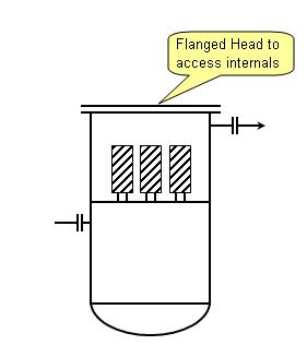
However, in small vessel with internals, a flanged head is preferred. Most of the time a swing davit will be installed on the flanged head to held the flange without assistance of any hoist.
Constructibility / fabrication limitation
Flanged head some time is used due to complexity of fabrication. There are many event where a inline condenser is mounted on top of a column.
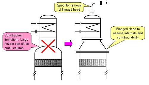
In some event where the column is small diameter (i.e. 1000mm) and a condenser with 800m ND needs to be mounted on top, there will be difficulties to use a elliptical head. those a flanged head with mating concentric reducer will be used. Apart it serve as manhole to access the internals such as demister.
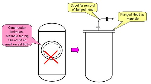
Cost Saving
Sometime process and operation may required a manhole (for any specific reason) on a small vessel. Apart from construction limitation, providing a flanged head will solve the constructibility problem, it also act as manhole. Some cost saving is expected.
Above are some common reasons for selection of head type. I am sure there are others special reason(s) for the selection in Petrochemical & Chemical industry. If you have any example, why not sure with us ? OR if you have any photos for above applications, why not sent to me so that i can upload here ?
Related Topics
- Hydraulic Design Of Liquid with Pump Circuit - A revision kit...
- Hydraulic Design of Liquid Piping Systems - A revision kit...
- Is pressure drop increase with pipe schedule ?
Labels: Design, Material, Tower internals
Sunday, December 9, 2007
 Natural Convection Phenomenon
An air-cooled heat exchanger fan off, heat transfer by natural convection may continuous where the air movement is resulted by the air density difference between cool ambient air and hot air (near tube with hot process fluid) within the tube bundle and duct. Natural air cooling may leads to some adverse and process problem. Two major examples are
1) waxy fluid crystallized & solidified and water freezing in air-cooled heat exchanger
2) Inability for vapor to condensed results vapor passing across air-cooled heat exchanger
Process design engineer shall address above scenarios as part of the design and understanding ability of natural air cooling becomes important.
Natural Convection Heat removal by Induced Draft & Forced Draft Fan
Works carried out by Berryman (1983) and Henry (1988) has shown that heat removal from induced draft and forced air cooler in the range of 20-40% and 5-15% (of normal heat duty) respectively. The percentage is increased with wind velocity. Refer to following image.
 Higher heat removal is expected in induced draft compare to forced draft. This could be caused by the location of fan and fan blades. In forced draft (where fan is located below the tube bundle), fan blades will create disturbance of air flow and affect proper air distribution across the tube bundle and leads to lower heat removal. Disturbance of air flow may increases the possibility of vortex (air recirculation) formation between the fan blades and tube bundle. Air recirculation will reduce net cool air intake into tube bundle and lower heat removal.
Credit During Fan Off
Apart from process issue as discussed, natural air cooling by air-cooled heat exchanger during fan off and/or shutdown condition will help to reduce process fluid temperature. In the event of power failure which lead to fan off, residue hot gas may continue pass through air-cooled heat exchanger and results downstream system temperature continue to rise. Natural convection will partially cool the hot gas. Determining quantity of heat removal by natural convection for CAPEX optimization and maintaining plant integrity is getting critical in this context. API has provides some allowance in natural convection. Per API STD 521, section 5.6.4 Air-Cooler fan failure, partial condensing capacity of 20% - 30% of normal duty can be taken for natural convection of air-cooled heat exchanger. However, API STD 521 has not differentiated allowance for induced draft and forced draft fan.
Additional Thought
Considering Berryman and Henry studies, credit statement in API STD 521 and still air condition, the reasonable heat removal by natural convection during fan off for induced and forced draft may be 20% and 5% of normal duty respectively.
Besides, as the reasonable heat removal only 5% for forced draft, it has minimum incentive for further optimization and process designer can choose to ignore. However, 20% for induced draft is at it lower end and has reasonable incentive for further optimization, thus process designer may consider take the allowance but shall always confirm with final design during detailed design and fabrication.
Related Topic
- Success story of turbulator in Air Cooled Heat Exchanger
- Heat Transfer Coefficient For Air-Cooled Heat Exchangers
- Air Cooled Heat Exchanger Control using Variable Pitch Fans
- Design of Quiet Air-Cooled Heat Exchangers
- Should Forced Draft or Induced Draft Air Cooler be employed on offshore platform?
Labels: Air Cooler, Fan, Forced Draft, Induced Draft
