Thursday, July 31, 2008
Display problem ? Click HERE
Recommended :
- Subscribe FREE - Processing Magazine
- Tips on Succession in FREE Subscription
 A catalytic-distillation process for the production of t-amyl-methyl-ether (TAME) from methanol and isoamylenes was simulated by developing the process model as a combination of unit operations from HYSYS operations palette. Geometrical characteristics of catalytic-distillation column are those of an industrial pilot plant and the results of simulation were compared with experimental data. The experimentally determined reactions kinetics was applied in the model. UNIQUAC-UNIFAC model equations were selected for the vapour-liquid equilibrium.
- Subscribe FREE - Processing Magazine
- Tips on Succession in FREE Subscription
A catalytic-distillation process for the production of t-amyl-methyl-ether (TAME) from methanol and isoamylenes was simulated by developing the process model as a combination of unit operations from HYSYS operations palette. Geometrical characteristics of catalytic-distillation column are those of an industrial pilot plant and the results of simulation were compared with experimental data. The experimentally determined reactions kinetics was applied in the model. UNIQUAC-UNIFAC model equations were selected for the vapour-liquid equilibrium.Catalytic Distillation Process Simulation using HYSYS
This paper presents a theoretical study for the modelling of reactive distillation column operation in t-amyl-methyl-ether (TAME) synthesis. The simulation procedure is based on a mathematical model considering chemical reaction kinetics for the main reactions and the vapour-liquid equilibrium. Phase contact in the reaction zone is described with the back-flow cell model.
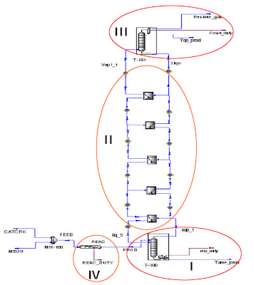
The problem statement in HYSYS.Process environment was made considering three zones for the catalytic distillation column (rectifying, reaction and stripping). Constructive and operational characteristics of the column are specified as a consequence of the parametric study: reaction zone position, feed position and reflux ratio, in order to obtain maximum yield for the transformation of C5 reactive olefins in the pilot plant. The simulation results are in good agreement with experimental data obtained in the experimental pilot plant at SNP PETROM, INCERP Ploiesti subsidiary. The quality of the results obtained in this paper is limited by the uncertainty introduced by the phase hydrodynamics in the reaction zone the phase equilibrium hypothesis.
Read more here...
Related Topic
Read more here...
Related Topic
Labels: HYSYS, Process simulation
Wednesday, July 30, 2008
Display problem ? Click HERE
Recommended :
- Subscribe FREE - Processing Magazine
- Tips on Succession in FREE Subscription
On May 2, 2008 at 1010 hours, during plant start-up towards the end of plant turnaround, an incident occurred in a cooling water cell where a contractor suffered several cuts resulted multiple injuries on his forehead, fractured elbows and collar bone after being hit by the fan blade. The fan was energized without notice and aware of contractor still working inside the cooling water cell.
The root cause as identified :
- Subscribe FREE - Processing Magazine
- Tips on Succession in FREE Subscription
On May 2, 2008 at 1010 hours, during plant start-up towards the end of plant turnaround, an incident occurred in a cooling water cell where a contractor suffered several cuts resulted multiple injuries on his forehead, fractured elbows and collar bone after being hit by the fan blade. The fan was energized without notice and aware of contractor still working inside the cooling water cell.
A TOTAL COMMUNICATION BREAKDOWN !!!
The root cause as identified :
- Communication breakdown between different parties (the contractor working at the fan blade, safety watch and the personnel who activated the push button).
- Insufficient understanding on the typical confine space safety requirements and the need to develop specific Job Safety Analysis (JSA) for the job.
- Procedure not comprehensive to address safe work method while performing the job.
- Inadequate lock-out tag out (LOTO) for in situ balancing trial run.
Recommended :
Subscribe FREE - Legal Aspects of Incident Investigation
 Lessons Learnt:
a) Enhance communication and to physically reconfirm that nobody is in the confine space prior to start-up of any equipment
b) Provide refresher briefing to all operation and maintenance staff on the typical confine space and JSA requirements.
c) Review procedure and include safe job method statement for in-situ balancing trial run.
d) Strengthened the LOTO mechanism for in-situ balancing trial run
e) Implement key-interlocking system where fan will not be energized until key kept by contractor is released.
Related Post
- "Fire from Ice" - Lesson Learned & Key Recommendations
- Compressed Gas Incident - Awareness & Learning Fundamentals...
- Pipeline rupture In Varanus Island
- Break the Rules... Pay the Price...
- Vacuum Hazard - Another Catastrophic Factor...
- Extra Caution When Eliminating Overpressure by Fire Attacks
- Blast rocks Texas oil refinery
Tuesday, July 29, 2008
Display problem ? Click HERE
Recommended :
- Subscribe FREE - Processing Magazine
- Tips on Succession in FREE Subscription
Have you ever dream of studying engineering in Massachusetts Institute of Technology (MIT) ? Now you may have chance to learn from MIT for FREE. Amusing !Since year 2000 MIT has started an initiative (called OpenCourseWare) to publish all their courses in the web for everybody to see, enjoy and learn. They have created a web site storing a the 1800 courses for public viewing, read, download, distribute, etc
All the content of courses includes lecture notes, laboratory exercises, tests and quizzes and the answers, and videos for some courses. The courses posted in this site are the real courses identical to the ones that are being offered at MIT campus.
Lecturer can download and use them for lecture purpose...
Student can read and learn...
Engineer can refresh their understanding and re-educate...

Knowledge is Own by Everyone
but Not Someone
Thanks to MIT to share...
- Click here to visit MITOpenCourseWare
- Click here to visit Chemical Engineering Courses
Related Post
- Tips on Succession in FREE Subscription
- Read Magazine To Success as Professional Engineer...Share To Assist More to Success
- Another NEW & FREE magazine - Pipeline & Gas Journal
- 3 Most Important & FREE Magazines That I Read...
- Chemical Engineering Digital Issue July 2008
Monday, July 28, 2008
Display problem ? Click HERE
Recommended :
Subscribe FREE - Processing Magazine
Liquid (operating temperature lower than maximum solar heating temperature) trapped in pressure vessel and piping and expose to solar heating, heat transfer into the liquid would cause liquid expansion. As liquid is “incompressible”, pressure can built up quickly and reach the maximum allowable working pressure (MAWP) of equipment and piping.
Subscribe FREE - Processing Magazine
Liquid (operating temperature lower than maximum solar heating temperature) trapped in pressure vessel and piping and expose to solar heating, heat transfer into the liquid would cause liquid expansion. As liquid is “incompressible”, pressure can built up quickly and reach the maximum allowable working pressure (MAWP) of equipment and piping.Pressure Vessel
For pressure vessel, the design code i.e. ASME Section 8 Div II always request a Pressure Relief Valve (PSV) for fire protection, thus this PSV would serve the thermal relief as well.
Piping
There is no such requirement for piping in general. However, API STD 521 2007 Addendum May 2008, section 5.14.1 (c) stated that hydraulic expansion due to solar heating on piping shall be assessed and checked if a pressure relief valve (PSV) is required. This section allows that a PSV may not required for thermal relief if proper administrative procedures and addition of signs stipulating the proper venting and draining procedures when shut-down and block-in are implemented. These action are acceptable and considered do not compromise the safety of personnel or equipment.
Common case
System under consideration for thermal relief consists of piping only (does not contain pressure vessels or heat exchangers), a pressure-relief device might not be required to protect piping from thermal expansion if :
- the piping is always contains a pocket of non-condensing vapour, such that it can never become liquid-full (even it is heated and compressed); OR
- the piping is in continuous use (i.e., not batch or semi-continuous use) and drained after being blocked-in using well supervised procedures or permits; OR
- the fluid temperature is greater than the maximum temperature expected from solar heating (the pipe temperature direct under solar heating can reached approximately 60 °C to 70 °C, it can be as high as 85 °C for certain area i.e. Middle east) and there are no other heat sources such as heat tracing; OR
- the estimated pressure rise from thermal expansion is within the design limits of the equipment or piping.
Some engineer may considered that insulates and buries pipe would avoid thermal relief. This is still an arguable statement. Insulation and buries would reduce heat inputs into the system, however, it does not completely avoid thermal relief. For example. an Liquefied Natural Gas (LNG) line from LNG plant to LNG storage may travel some distance. Although the line is insulated, the operating temperature of this can be as low as -140 degC to -150 degC. As compare to ambient temperature, there is still potential of heat leakage via insulated line and results vaporization.
 With above statements and conditions, the piping within a plant is normally not equipped with PSV for thermal relief.
Special case
For some special case, a long piping i.e. piping between unit and/or plant may potentially experience overpressure caused by solar heating. A small Pressure Relief Valve is general provided for overpressure protection due solar heating.
The length and diameter of the piping and PSV with D-orifice sufficiently prevent overpressure protection are still remain a question.
The following studies will try to figure out the length and diameter limit for a D-orifice PSV.
Methodology
Method stipulated in API STD 521 2007 Addendum May 2008 section 5.14.3 will be used to calculate the pressure rise and liquid expansion rate (hence thermal relief rate).
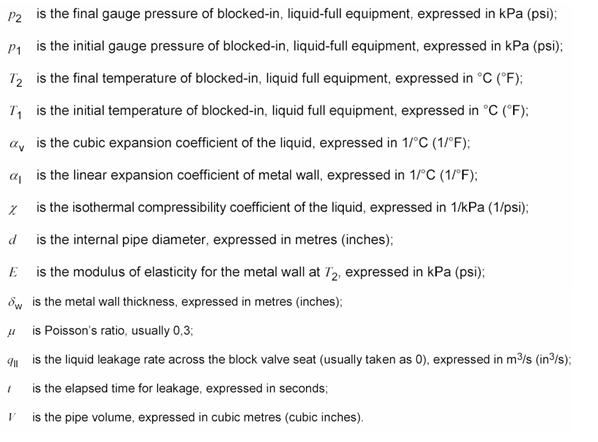
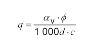
Pressure rise is estimated with following equation
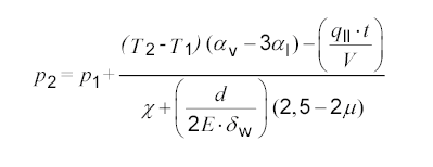
Where
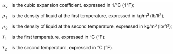
 Cubic expansion coefficient is estimated base on
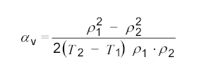
Where
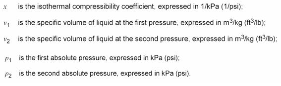
Isothermal compressibility coefficient is estimated base on :
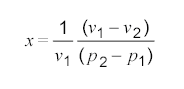
Where
Liquid expansion rate is estimated base on :
Where
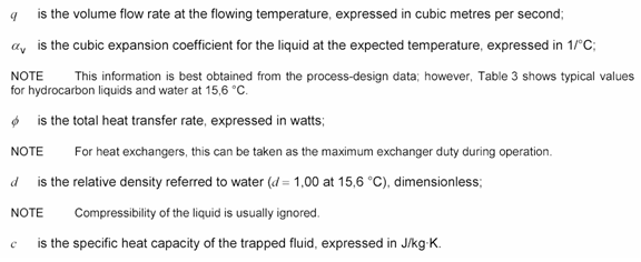 Refer to API STD 521 2007 Addendum May 2008 for formulation & definition Above has been modeled HYSYS for ease of calculation and data manipulation.
Assumption & Basis
Several assumption & basis have been considered :
- Solar heating is potentially ranging from 0.79 to 1.04 kW/m2. Nevertheless, 1.15 kW/m2 has been considered in this study for conservativeness.
- As it is difficult to ensure if total or partial piping surface area of the pipe is expose to solar heating, thus entire (100%) surface area of the pipe is assumed expose to solar heating.
- It is assumed solar heating potential heat the piping and liquid to 60°C.
- Design pressure of the piping is at 16 barg. It is considered the PSV will open at 16 barg.
- It is considered that the fluid content and piping has been heated and pressure has built-up to 15.9 barg (0.1 bar below the PSV set pressure). This will potentially lead to maximum liquid relieving rate.
- The studies have considered water(H2O), I-butane (iC4), hexane (C6), nonane (C9) and decane (C10)
- For 150# Carbon Steel (CS),
- Linear expansion coefficient is taken as 1.21 x 10⁻⁵ 1/°C
- Modulus of Elasticity is taken as 207 x 106 kPa
- Wall thickness is taken as 6.35mm
Refer to following figure.
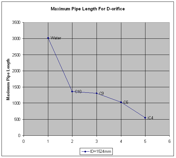
For a pipe with ID of 1524mm, the maximum pipe length lead to flow limit of D-orifice are listed as follow :
Water - 3026 m
C10 - 1365 m
C9 - 1311 m
C6 - 1029m
iC4 - 556m
If a pipeline contain iC4 with length less than 556m, a D-orifice is sufficient to protect the pipeline from solar heating overpressure protection. If exceeded 556m, a E-orifice or 2 x D-orifice may be required.
Refer to following figure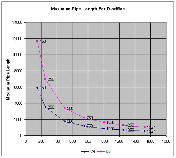
For a pipe containing iC4 (and C6 for second case), the maximum length for different pipe diameter are listed as follow :
ID - iC4 - C6
ID = 150mm - 5910 m - 11684 m
ID = 250mm - 3534 m - 6943 m
ID = 500mm - 1751 m - 3393 m
ID = 750mm - 1158 m - 2214 m
ID = 1000mm - 861 m - 1628 m
ID = 1250mm - 683 m - 1279 m
ID = 1524mm - 556 m - 1029 m
ID = 150mm - 5910 m - 11684 m
ID = 250mm - 3534 m - 6943 m
ID = 500mm - 1751 m - 3393 m
ID = 750mm - 1158 m - 2214 m
ID = 1000mm - 861 m - 1628 m
ID = 1250mm - 683 m - 1279 m
ID = 1524mm - 556 m - 1029 m
Any point below under curve implies a D-orifice is sufficient.
Concluding remark
Above briefly inform that only a small PSV (i.e D-orifice) is required for thermal relief for piping. Length limitation has been quickly established.
Related Post
- Back Pressure Affect Conventional PSV Set Pressure : Case Study #2 - Non-Bonnect Vent
- Back Pressure Affect Conventional PSV Set Pressure : Case Study #1 - Bonnect Vent to ATM
- How Back Pressure Affect Conventional PSV Set Pressure Subject to It Vent
- Several Impact of Backpressure on Conventional PSV
- Simple Flow Chart to Determine Requirement of Thermal Relief
- Why Rupture (RD) Upstream of Pressure Relief Valve (PRV) ?
- Why Two Rupture Discs in Series ?
- Tube Rupture : Pressure Relief Valve (PSV) or Rupture Disk (RD) ?
- Criteria for Requirement of Pressure Relief Device for Tube Rupture
Labels: Overpressure Protection, Pressure Relief Device
Sunday, July 27, 2008
Display problem ? Click HERE
 As an effort to assist every readers to success as Professional Engineer, we have worked with our partner, Netline to offer our readers FREE magazines* subscription to all our readers. We have noticed that many reader failed in subscription request. Those, we take efforts to discuss some tips lead to Succession in FREE Subscription.
There are few main factors affecting the succession in subscribing to FREE magazine. The following will discuss the factors and some tips to assist you to get higher chance in FREE subscription.
Limited FREE offer
As an effort to assist every readers to success as Professional Engineer, we have worked with our partner, Netline to offer our readers FREE magazines* subscription to all our readers. We have noticed that many reader failed in subscription request. Those, we take efforts to discuss some tips lead to Succession in FREE Subscription.There are few main factors affecting the succession in subscribing to FREE magazine. The following will discuss the factors and some tips to assist you to get higher chance in FREE subscription.
Each magazine will have limited offer for a dedicated promotion period.Those it is based on first come first serve basis. Once you are aware of availability of particular magazine, apply immediately with out delay.
TIPS : First come first serve. Apply immediately
Answer ALL Question with Honest
As requested, applicant shall answer ALL question in the questionnaire honestly. ANALYZE the question in regards to magazine content and applicant relevancy. DO NOT miss any question.
TIPS : Analyze then Answer. Don't miss !
Geographical location
Each magazine publisher will offers FREE subscription to a specific geographical location in accordance to its timely promotion campaign and marketing strategy. Free subscription will only be approved to those applicant from applicable geographical location. However, one may remember, the publisher may change from time to time according to its market strategy. You may check from time to time.
This is one of the most common factor seriously affects the succession in FREE subscription. If you came from geographical location NOT inline with the applicable geographical location, you need try your luck. There is a sophisticated system capable of detecting the IP address of your workstation and the system capable of understand which country the application came from. If it is not inline with the applicable geographical location, it will be rejected immediately without further screening.
If you happen to be outstation in applicable geographical location i.e USA, CANADA, etc, take this opportunity to apply for FREE magazine. It might help.
TIPS : Take all opportunityIf you happen to be outstation in applicable geographical location i.e USA, CANADA, etc, take this opportunity to apply for FREE magazine. It might help.
Organization Capacity
Some of the publisher have specific target market. They will only approve those professional from organization with certain capacity and size i.e. company A with employee more than 500. Thus, larger your organization, higher succession rate. One may remember, the employee could includes all level of employee e.g. management, executive staff, engineer, etc. It may be only limited to engineer only.
TIPS : Large organization, higher conversion to advertiser.
Organization Business Nature
Applicant Position/Job Title
TIPS : Large organization, higher conversion to advertiser.
Organization Business Nature
Some of the publisher is only targeted to certain organization with business nature. For example, Chemical Engineering magazine may only approve those application from Chemical / Petrochemical / Oil & Gas related organization. If an applicant from Financial institute i.e ABC Bank, i doubt the application will success in the subscription. Organization matching is another factor affect the success of this subscription.
TIPS : Organization matching Content
TIPS : Organization matching Content
Applicant Position/Job Title
This is another important factor affects the succession of subscription. A particular magazine may target to certain group of professional. For example, Offshore engineer magazine publisher may not approve an applicant with job title of accountant. As the content as well as the advertiser in this magazine is relevant and targeted to Offshore Engineer. Job title matching magazine content is a very important factor.
TIPS : Job title matching Content
Magazine format
Some of the magazine will be issued in hardcopy and / or digital version. Digital here means electronic magazine (generally in pdf format). To promote Green engineering and minimize usage of paper, to minimize publishing cost e.g.printing, storage, handling and transportation, by saving cost it allow higher chances of FREE subscription as well as more longer subscription, you are encourage to request the DIGITAL format.
TIPS : DIGITAL only
Verification
There is a simple question to verify you as subscriber (instead of machine or robot generate form), the question is more human/subscriber related i.e where you were born, where you are working, etc. Fill it wisely.
TIPS : Read, Understand & Fill wisely
Notification of Other Publication
One of check box in the form you may consider to check but it is subject to you willingness. The content of this check box is "Yes. please auto-fill my contact information for other publication qualification forms.". By check this box, you will be notified with other FREE publication.
TIPS : Allow Further Notification
Last but not lease, above are some factors possibly increase the opportunity in subscribing to FREE magazine (without warranty). More important is you obtain the required information and knowledge with these magazine. Likewise, you shall take the effort to fill the subscription form.
Click here to obtain others FREE Magazine Subscriptions & Technical Document Downloads
* For qualified professional.
Related Post
- Read Magazine To Success as Professional Engineer...Share To Assist More to Success
- Another NEW & FREE magazine - Pipeline & Gas Journal
- 3 Most Important & FREE Magazines That I Read...
- Chemical Engineering Digital Issue July 2008
- Don't miss CHEMICAL ENGINEERING Supplementary Issue in Chinese...
- Non - Technical Quick References for a Chemical & Process Engineers
- Chemical Engineers Top Salary Ladder
Labels: E-Doc, Education, Learning
Saturday, July 26, 2008
Display problem ? Click HERE
Recommended :
Subscribe FREE - World Pump

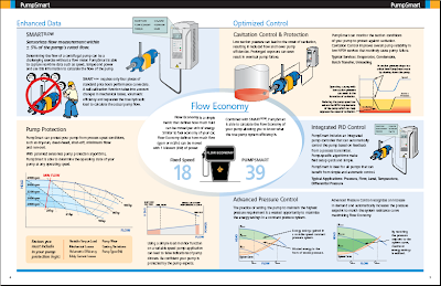
PumpSmart is an intelligent system includes the advanced pump Control, Protection, and Optimization logic designed to prevent failures, improve pump reliability and maximize the Flow Economy of process systems. It is one of the great product by ITT PumpSmart Control Solutions. PumpSmart utilizing smart VFD controller and ITT proprietary control software to provide advanced process control, enhanced reliability through failure prevention, reduced life cycle costs and lower energy costs - up to 65%.
PumpSmart can :
Visit PumpSmart
PumpSmart presentation (Video Clip)
(Click here to view using Web Browser)
Subscribe FREE - World Pump
PumpSmart is an intelligent system includes the advanced pump Control, Protection, and Optimization logic designed to prevent failures, improve pump reliability and maximize the Flow Economy of process systems. It is one of the great product by ITT PumpSmart Control Solutions. PumpSmart utilizing smart VFD controller and ITT proprietary control software to provide advanced process control, enhanced reliability through failure prevention, reduced life cycle costs and lower energy costs - up to 65%.
PumpSmart can :
- works with any pump.
- capture real-time data such as speed, torque and power to calculate the flow of the pump.
- protect pump from process upset conditions such as dry-run, dead-head, shut-off, minimum flow and run-out.
- monitor pump suction conditions to protect against cavitation and improves overall pump reliability
- control the pump based on feedback from a process transmitter.
- calculate the Flow Economy of pump and true pump system efficiency.
Visit PumpSmart
PumpSmart presentation (Video Clip)
(Click here to view using Web Browser)
Related Topic
- Vortex Breaker to Avoid Vapor Entrainment
- Estimate Minimum Submergence to Avoid Vapor Entrainment
- Estimate Pump Power Consumption without Vendor Information
- Trim Centrifugal Pump Impeller for Reduced Head
- Quick Check if Pump Performance Curve (Water) is Good for High Viscosity Fluid
- Quick Check if NPSHa is Sufficient Using Thoma Cavitation Curve
- Quick Pump Selection...
Labels: Pump
Friday, July 25, 2008
Display problem ? Click HERE
CLICK HERE to Subscibe FREE...
 Chemical Engineering (CE) released a special issue for Flowmeter & Piping recently. There are available FREE for subscribers. If you are not a CE subscriber yet, you may subscribes FREE issue of CE*** by clicking this link.
***The CE subscription is hot and may temporary unavailable. If it is unavailable, you are encouraged to revisit the link one week after. FREE CE subscription only for qualified professional.
Managing Measurement Costs in Automated Water Treatment Systems Using Smart Sensing and Blind Transmitter Technology
By Dave Vollaire, GF Piping Systems
Installed cost per measurement is an important factor for industrial water and wastewater treatment professionals focused on system design. Modern treatment systems are highly automated and a significant portion of equipment and installation cost belongs to measurement and instrumentation components. When installation costs are removed from the equation, it becomes clear that measurement and instrumentation components alone can account for up to 50 percent of the total equipment cost. Newer technologies such as smart sensing, multi-channel, multi-parameter instrumentation, as well as blind transmitter technology, can significantly reduce the cost per measurement over the traditional single point controller schemes in automated water treatment systems....
For CE subscriber only...Click here to read
(Not CE subscriber ? Try subscribes for FREE CE... Click HERE***)Chemical Engineering (CE) released a special issue for Flowmeter & Piping recently. There are available FREE for subscribers. If you are not a CE subscriber yet, you may subscribes FREE issue of CE*** by clicking this link.***The CE subscription is hot and may temporary unavailable. If it is unavailable, you are encouraged to revisit the link one week after. FREE CE subscription only for qualified professional.
Managing Measurement Costs in Automated Water Treatment Systems Using Smart Sensing and Blind Transmitter Technology
By Dave Vollaire, GF Piping Systems
Installed cost per measurement is an important factor for industrial water and wastewater treatment professionals focused on system design. Modern treatment systems are highly automated and a significant portion of equipment and installation cost belongs to measurement and instrumentation components. When installation costs are removed from the equation, it becomes clear that measurement and instrumentation components alone can account for up to 50 percent of the total equipment cost. Newer technologies such as smart sensing, multi-channel, multi-parameter instrumentation, as well as blind transmitter technology, can significantly reduce the cost per measurement over the traditional single point controller schemes in automated water treatment systems....
For CE subscriber only...Click here to read
GF Piping Systems New Metal Magmeter Configuration Expands Application Range and Versatility
By GF Piping Systems
TUSTIN, Calif. – June 26, 2008 – GF Piping Systems has added to its proven Signet 2552 Metal Magmeter family with the new Model 2552-3. The Signet Metal...
For CE subscriber only...Click here to read
(Not CE subscriber ? Try subscribes for FREE CE... Click HERE***)
For CE subscriber only...Click here to read
(Not CE subscriber ? Try subscribes for FREE CE... Click HERE***)
GF Piping Systems Introduces Next Generation DryLoc® pH and ORP Sensors Offering Enhanced Chemical Compatibility and Versatile Mounting Options
By GF Piping Systems
TUSTIN, Calif. – July 8, 2008 – GF Piping Systems has introduced the next generation of Signet DryLoc pH/ORP Sensors, Models 2724 − 2726. These sensors feature...
For CE subscriber only...Click here to read
(Not CE subscriber ? Try subscribes for FREE CE... Click HERE***)
For CE subscriber only...Click here to read
(Not CE subscriber ? Try subscribes for FREE CE... Click HERE***)
GF Piping Systems Introduces USB Interface for Signet Sensors, Offering Diagnostics, Parameter Configuration and Data Monitoring Capabilities
By GF Piping Systems
TUSTIN, Calif. – Nov. 8, 2007 – GF Piping Systems has introduced the Signet 3-0250, a new interface device that allows USB connection of blind Signet Sensors to...
For CE subscriber only...Click here to read
(Not CE subscriber ? Try subscribes for FREE CE... Click HERE***)
For CE subscriber only...Click here to read
(Not CE subscriber ? Try subscribes for FREE CE... Click HERE***)
FAYF - FLOWMETER SELECTION
by Rebekkah Marshall
Briefly discusses general selection criteria, flowmeter accuracy and turndown...
Click here...
Recommended :
Subscribe FREE - Processing Magazine
Following are 6 articles in series related to Piping for Process Plants. by W. M. Huitt, W. M. Huitt Co.Piping for Process Plants Part 1: The Basics
Pipe, fittings and related equipment are fundamental to the operation of chemical process plants. The series of articles beginning with this one spells out the details. This is the first in a series of articles that will cover a wide range of piping topics. The topics will cross process-industry lines, pertaining to, for example, the chemical, petroleum-refining, pulp-and-paper and pharmaceutical and other industries.The main intent of these articles to address questions and misunderstandings as they relate to use of piping on a general basis.
Typical of the topics that will be covered in this series are the following:
* With respect to ASME flange ratings — Is the correct terminology 150- and 300-pound flange, or is it Class 150 and Class 300 flange? And do the 150 and 300 actually mean anything, or are they simply identifiers? Similarly, with respect to forged fittings, is the terminology 2,000-pound and 3,000-pound, or is it Class 2000 and Class 3000?
For CE subscriber only...Click here to download(Not CE subscriber ? Try subscribes for FREE CE... Click HERE***)
Piping Design, Part 2 - Flanges
The engineer or designer must choose among several flange options. Additional decisions involve facing and surface finishes, and the appropriate gaskets, bolts and nuts. Pipe flanges are used to mechanically connect pipe sections to other pipe sections, inline components, and equipment. Flanges also allow pipe to be assembled and disassembled without cutting or welding, which eliminates the need for those two operations when dismantling is required. In providing a breakable joint, however, flanges unfortunately provide a potential leak path for the process fluid contained in the pipe. Because of this, the usage of flanges needs to be minimized where possible, as with all other joints.
For CE subscriber only...Click here to download(Not CE subscriber ? Try subscribes for FREE CE... Click HERE***)
Piping Design, Part 3 - Design Elements
Design requires a systematic methodology, planning, technical ability, interdisciplinary coordination, foresight and, above all, experience. Piping design is the job of configuring the physical aspects of pipe and components in an effort to conform with piping and instrumentation diagrams (P&IDs), fluid-service requirements, associated material specifications, equipment-data sheets, and current good manufacturing practices (GMP) while meeting owner expectations. All of this must be accomplished within a pre-determined, three-dimensional assigned space, while coordinating the activity with that of the architecture, structural steel, HVAC (heating, ventilation air conditioning), electrical, video, data-and-security conduit and trays, and operational requirements.
For CE subscriber only...Click here to download(Not CE subscriber ? Try subscribes for FREE CE... Click HERE***)
Piping for Process Plants, Part 4: Codes and Fabrication
Besides flanges, there are also several different types of joints and welding processes to choose from. Additional decisions involve piping codes. This fourth in a series of articles* on piping for process plants examines two topics that may, at first, seem to fall outside the scope of chemical engineering — piping codes and the pipe fabrication. Obviously chemical engineers will not be welding pipes together, but understanding the benefits and limitations of different types of welding processes, for example, can help the engineer when designing the system that needs to be welded.
For CE subscriber only...Click here to download(Not CE subscriber ? Try subscribes for FREE CE... Click HERE***)
Piping Design Part 5: Installation and Cleaning
These practical guidelines for deciding which installation procedure to follow, and for cleaning a new pipeline system can prevent problems from happening during startup. This fifth in a series of articles [1 – 4] on piping design discusses the practical issues of installation and cleaning. The installation of pipe follows its fabrication and is very frequently a part of it. The installation of pipe can be accomplished in the following four primary ways, or combinations thereof:
For CE subscriber only...Click here to download(Not CE subscriber ? Try subscribes for FREE CE... Click HERE***)
Piping for Process Plants Part 6: Testing & Verification
Proper documentation, determination of the fluid service category and operating conditions are among the factors necessary to perform the correct leak test on a piping system. This sixth and final part of a series of articles [ 1 – 5] on piping for process plants discusses practical issues of leak testing and verification of piping systems. Leak testing and pressure testing are often used synonymously. However, pressure testing is a misnomer when referring to leak testing of piping systems. By definition, a pressure test is the procedure performed on a relief valve to test its set-point pressure. The intent, when pressure testing a relief valve, is not to check for leaks, but to test the pressure set point of the valve by gradually adding pressure to the relief valve until it lifts the valve off of the seat.
For CE subscriber only...Click here to download(Not CE subscriber ? Try subscribes for FREE CE... Click HERE***)
Related Post
- Flow Element (FE) Upstream or Downstream of Control Valve (CV) ?
- Use Ultra-Sonic Flowmeter in FLARE Gas Header for emission monitoring
- FAYF - Flowmeter selection in brief...
- Useful Documents Related to Control Valve
- Restrcition Orifice Used in Many Applications in Different Manners
- A refresh to Process Engineer on few phenomenons in restriction orifice
- Why Restriction Orifice is some distance from Blowdown valve ?
Wednesday, July 23, 2008
Display problem ? Click HERE
Recommended :
Subscribe FREE - Processing Magazine
A question raised by a young engineer.Should a Flow element (FE) be located upstream or downstream of a control valve (CV) ?
There is no fix rules governing the location of this flow element. It is very much subject to few factors i.e. fluid condition of the measured fluid, properties fluctuation, etc.
a) Fluid Characteristic
A flow element is general prefer single vapor or liquid phase as compare to two phases gas-liquid (2Ph-GL) flow. First to check is the fluid characteristic downstream of control valve. For example, liquid control valve (LCV) maintaining level of a separator. The fluid feeding the LCV is probably a liquid at bubble point. Due to static head it potentially maintain as liquid from separator outlet nozzle upto LCV. However, there is pressure drop across the LCV and 2Ph-GL flow is likely to occur downstream of LCV. Under this condition, it is always prefer to locate flow element upstream of LCV.
Let take another example for vapor flow line. A pressure control valve (PCV) maintaining a constant saturated gas flow to downstream system i.e. fuel gas system from a separator. In the event there is large pressure drop across the PCV, Joule-Thompson (JT) effect results significant liquid formation downstream of PCV. Similarly, it is always prefer to locate flow element upstream of PCV.
b) Pressure & Temperature Fluctuation
Large pressure and temperature fluctuation would probably leads to properties (i.e density) changes. In general, a vapor system would experience severe changes as compare to liquid system. Thus, large pressure and temperature fluctuation may results a large deviation in properties and lead to difficulties in select a good flow element for the service. It is always prefer to locate flow element in the stream with "less" properties change .
For example, a slug catcher is having a pressure control valve (PCV) feeding gas to booster compression system. The booster compression is targeted to maintain a constant pressure of
Recommended :
Subscribe FREE - Chemical Processing

the suction scrubber. As slugcatcher pressure (upstream of PCV) may fluctuate due to slugging and pigging operation whilst the pressure (downstream of PCV) at compressor suction scrubber is rather constant, it is always prefer to locate flow element downstream of PCV. It shall be noted that there is potential liquid formation downstream of PCV which prefer to locate PCV upstream of PCV. Both rule-of-thumbs are contradicting between each and other, a process engineer shall weight both impacts to locate it at right location.
For example, a slug catcher is having a pressure control valve (PCV) feeding gas to booster compression system. The booster compression is targeted to maintain a constant pressure of
Recommended :
Subscribe FREE - Chemical Processing
the suction scrubber. As slugcatcher pressure (upstream of PCV) may fluctuate due to slugging and pigging operation whilst the pressure (downstream of PCV) at compressor suction scrubber is rather constant, it is always prefer to locate flow element downstream of PCV. It shall be noted that there is potential liquid formation downstream of PCV which prefer to locate PCV upstream of PCV. Both rule-of-thumbs are contradicting between each and other, a process engineer shall weight both impacts to locate it at right location.
c) Pressure Rating
High pressure rating of flow element will be costly. Thus, it is always prefer to locate the flow element at the system with lower pressure rating, downstream of control valve.
d) Vibration
Pressure drop across control valve would partially convert its energy to noise and vibration. The vibration (higher intensity) would travel along fluid flow direction. Some flow element (i.e. Coriolis,Vortex) is sensitive to vibration. Vibration sensitive flow element is always advisable to locate upstream of control valve.
A process engineer may consider above factors to locate the flow element. Apart, process engineer is always advisable to verify this subject with instrument engineer and vendor for proper location and correct flow meter type.
Related Post
- Use Ultra-Sonic Flowmeter in FLARE Gas Header for emission monitoring
- FAYF - Flowmeter selection in brief...
- Useful Documents Related to Control Valve
- Restrcition Orifice Used in Many Applications in Different Manners
- A refresh to Process Engineer on few phenomenons in restriction orifice
- Why Restriction Orifice is some distance from Blowdown valve ?
Labels: Flowmeter, Fluid Flow, Hydraulic
Tuesday, July 22, 2008
Display problem ? Click HERE
Recommended :
Subscribe FREE - Processing Magazine
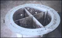
A free surface vortex can form when a liquid exit via a nozzle or hole below it liquid surface (bottom or side). Minimum submergence height (S), can be calculated according to earlier post"Estimate Minimum Submergence to Avoid Vapor Entrainment" shall be maintained in order to avoid gas entrainment in the the liquid outlet. In case of gas entrainment into pump, it will reduce pump capacity and potentially affect the plant performance.In some cases, the estimated minimum submergence height (S) could be high and it may not be cost effective and providing vortex breaker is another option to tackle gas entrainment issue. A vortex breaker is a simple plate(s) arrangement which intentionally to break the vortex vertically or horizontally. Following images are some plate arrangement which may be used as vortex breaker.

The first three are basically a horizontal plate to segregate vortex from inlet while last (bottom) is vertical plates (4 or 6 plates) to break circulation of liquid. Following images are some typical applications of vortex breaker.

Related Topic
- Estimate Minimum Submergence to Avoid Vapor Entrainment
- Estimate Pump Power Consumption without Vendor Information
- Trim Centrifugal Pump Impeller for Reduced Head
- Quick Check if Pump Performance Curve (Water) is Good for High Viscosity Fluid
- Quick Check if NPSHa is Sufficient Using Thoma Cavitation Curve
- Quick Pump Selection...
Labels: Pump
Monday, July 21, 2008
Display problem ? Click HERE
Recommended :
Subscribe FREE - Processing Magazine
A free surface vortex potentially form when :i) liquid exit via a nozzle or hole below it liquid surface (bottom or side) and
ii) liquid height (between liquid surface and nozzle/hole) is below a minimum submergence height (S).
When free surface vortex is formed, gas entrainment will occur and pull vapor / gas above liquid surface exit together with liquid via the nozzle / hole. The following image shows series of events taken place when a free surface vortex is formed.
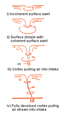
Similarly, gas entrainment occurs at pump suction intake point causes vapor/gas enter pump reduce pumping capacity and vibration (due to pump impeller imbalance).
Submergence (S) is defined as the height between liquid surface and the exit hole. Following images show submergence (S) for different intake location and nozzle type.

Submergence subjects to intake velocity with the following relationship :
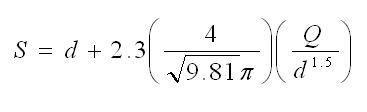
where
d = intake diameter (m)
Q = intake flowrate (m3/s)
Example :
A pump transferring liquid from a suction tank to a reactor at a rate of 227.1m3/h. The pump suction inlet nozzle with a internal diameter of 304.9mm is located horizontally. What is the minimum submergence to avoid gas entrainment ?
d = intake diamter = 304.9 /1000 = 0.3049 m
Q = intake flowrate = 227.1 / 3600 m3/h = 0.063 m3/s
S = 0.3049 + 2.3 (4 / SQRT(9.81) x PI) (0.063 / 0.3049)
S = 0.66 m
Thus, minimum submergence (S) is 0.66 m above intake nozzle.
* SQRT = Square-root
** PI = 3.141592654
Related Topic
- Estimate Pump Power Consumption without Vendor Information
- Trim Centrifugal Pump Impeller for Reduced Head
- Quick Check if Pump Performance Curve (Water) is Good for High Viscosity Fluid
- Quick Check if NPSHa is Sufficient Using Thoma Cavitation Curve
- Quick Pump Selection...
- Estimate Pump Efficiency base on Specific Speed (Ns)
- Pump Efficiency Estimation Without Vendor Information
Labels: Pump
Saturday, July 19, 2008
Display problem ? Click HERE
There are million of magazines available in the market covering almost all aspects and specialties. The magazines can be :
- subscribed with fees (most of them)
- subscribed FREE together with your subscription with an organization (i.e CEP for AICHE, TCE for IChemE)
- absolutely subscribed FREE
Being one of loyal reader of Chemical & Process Technology, i am pretty sure all of you should have read at least one or two magazines on regular basis. Have you ever asked why should you read magazine ?
You may already have the answer for it. Why not read how we think about it and share yours.
What is magazine
Before i proceed to discuss why should we read magazine, first thing we may have to ask what is magazine. Magazines, periodicals or serials are publications, generally published on a regular schedule, containing a variety of articles, generally financed by advertising, by a purchase price, or both. Read more here.
Why i read magazine
In earlier post "3 Most Important & FREE Magazines That I Read...", it informed that being a professional engineer (PE) for many years in Chemical & Process and Oil & gas field, three reputable magazines which i continue reading and update myself without fail. There are Chemical Engineering Progress (CEP), Chemical Engineering (CE) and Hydrocarbon Processing HP). Read more here.
There are few major benefits and reasons for reading magazine :
a) UPDATE Latest Information
You may read books for all the background, theory, application and example. You may also read journal for all the hypothesis, details analysis, data, supporting document, etc. However, books capture those accumulated information for the past decade while journal capture those latest noble and scientific development which may/ may not be used and practiced in real world. MAGAZINE is published on regular basis to update you with latest practical information, news, methodology, approaches, knowledge, tips, rule-of-thumb, etc
I have seen in many events, a valuable knowledge & practical experience, the content depth does not enough to be captured and published in journal (journal have stringent requirement on publication), the best place is MAGAZINE. For example, "Accurate Wetted Areas for Partial Filled Vessel", "3 effective ways to control a heat exchanger", etc. These articles do not have noble theory supporting it nor detail scientific analysis, but they are practical and useful experiences can be adopted by others engineer and simple tips/ rule-of-thumb to save your time.
b) STIMULATE idea
With all the efforts of your team, there are still no viable idea and solution for a particular problem. Browsing MAGAZINE is one of the way i find very useful. When you reading the experiences by other engineers in MAGAZINE, it will stimulate your brain the work out some new idea and approach to tackle problem.
c) EXPERT POOL
Once you found an useful knowledge and practical experience by an expect who authored the article, the author contact is always available at the end of the article. We may contact the author for further information and assistance. This is one of the fastest way to find the right people to assist you solving your problem. In addition, the contacts can be collected for future reference. The collection will form the expert pool for yourself and they are readily to assist you.
d) REFERENCE
As mentioned in (a), the MAGAZINE capture those most practical and useful experiences can be adopted by others engineer and simple tips/ rule-of-thumb to save your time. In many event, it can be used as reference and supporting document for your works and report
e) RESOURCE
Articles published in a reputable and reliable MAGAZINE, one of the requirement is author shall list out the reference and supporting documents for their article. By reading this reference and supporting documents, it will further expands your search & knowledge and save your time to find new information and articles
MAGAZINE is obviously a very useful media helping us in achieving our success as engineer. As an Professional Engineers (PE), reading reliable and reputable magazines already part of our works or part of out life to be exact. You are encourage to do the same.
How We Can Assist You
As an effort to assist you to success as Professional Engineer, we have worked with our partner, Netline to offer our readers FREE magazines* subscription to all our readers. Few recommended MAGAZINE for you are Hydrocarbon Processing, PipeLine and Gas Technology (PGT) and Chemical Processing (CP). You may click here for other FREE magazine...
How You Can Assist Your Friend
To assist your friends to success as Professional Engineer as well, you may inform them by clicking this link.
How You Can Assist Yourself & Others
Now is the most important part. How should you assist yourself, your friends and others to success as Professional engineers. Chemical & Process Technology has recently worked together with Netline in order to provides FREE magazines* subscription to all our readers. Just wanna to inform you that you may do the same like Chemical & Process Technology to provide FREE magazines* subscription to your friends and your readers if you have any blog and website. What you needs to works with our partner, Netline.
Netline, established since 1994, offers free B2B magazine subscriptions and other business resources, including informative white papers, analyst reports, live and on-demand webinars, podcasts, and more, across a wide range of industries. RevResponse as interface and managing this activity, puts this content at your fingertips, enabling you to provide your visitors with a free resource library that will keep them coming back again and again. If you want to see more, simply click here and take a look at the diverse selection. By introducing magazine to your friend and your blog/website visitor, Netline will award you with some $$ on every success subscription.

Let share this with you friend (click here to share) and let works together (click here to be partner) to assist yourself and your friend to success as Professional engineer and to promote professionalism.
* For qualified professional.
Related Post
- Another NEW & FREE magazine - Pipeline & Gas Journal
- 3 Most Important & FREE Magazines That I Read...
- Chemical Engineering Digital Issue July 2008
- Don't miss CHEMICAL ENGINEERING Supplementary Issue in Chinese...
- Non - Technical Quick References for a Chemical & Process Engineers
- Chemical Engineers Top Salary Ladder
Labels: E-Doc, Education, Learning
Friday, July 18, 2008

Subscribe FREE - Processing Magazine
Earlier post "Back Pressure Affect Conventional PSV Set Pressure : Case Study #1 - Bonnect Vent to ATM" has discussed how backpressure affects a conventional type Pressure Relief Valve (PSV) with bonnet vent to ATM and checks required to ensure the system is healthy.Similarly this post is a case study for a conventional type PSV with non-bonnet vent (bonnet vent to flare system). Let take the similar conditions as per case study #1 for easy comparison.
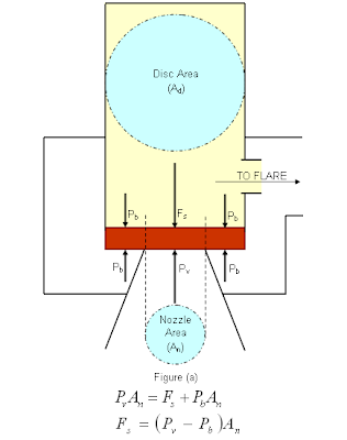
"A Pressure Relief Valve (PSV) is conventional type with bonnet vent to atmosphere. This PSV is protection a pressure vessel with pre-specified design pressure of 7 barg. Maximum expected operating pressure (MOP) of the system is about 6.2 barg. The vessel has a maximum allowable working pressure (MAWP) of 8 barg. The normal continuous superimposed back pressure (PBs) is zero barg (atmosphere). PSV set pressure (Pset) has been adjusted to be inline with design pressure (DP) of 7 barg. The PSV spring has been pre-set to open when the pressure is reach 7 barg. Disc area (Ad) and nozzle area (An) are 113mm2 and 71mm2 respectively (for illustration purpose only).
Plant debottlenecking has introduced a new Pressure control valve (PCV) continuous releasing vapor into the common flare header as the PSV. This has resulted a constant superimposed back pressure of 0.3 barg. As per early post "How Back Pressure Affect Conventional PSV Set Pressure Subject to It Vent", increases in superimposed back pressure will increase opening pressure of conventional PSV (open at higher pressure), is the system still healthy ?"
From above system description;
- PSV type : Conventional type PSV with non-bonnet vent (bonnet vent to Flare).
- DP = 7 barg
- Pset (=Pv) = 7 barg
- MOP = 6.2 barg
- MAWP = 8 barg
- PBs,norm = zero barg (atmosphere)
- Ad = 113 mm2
- An = 71 mm2
The spring has been pre-set to open at DP = 7 barg and expected to reach complete opening at/below 7.7 barg.
After debottlenecking...
With superimposed back pressure, Pbs=0,
==> Fs = (Pv - Pb)An
==> Fs = (Pv - 0)An
==> Fs = PvAn
==> Fs = (Pv - 0)An
==> Fs = PvAn
After debottlenecking and new PCV results increased superimposed back pressure to P'b=Pbs=0.3 barg,
(P'v is new pressure causing PSV starts to open)
==> P'vAn = Fs + P'bAn
==> P'vAn = PvAn + P'bAn
==> P'v = Pv + P'b
==> P'v = 7 + 0.3
==> P'v = 7.3 barg
Thus, PSV will only open at P'v = 7.3 barg.
MOP / P'v = 6.2 / 7.3 = 84.9% < 90%. This is OK for conventional type PSV.
Built-up back pressure (Pbb) shall be calculated (say 0.4 barg),
Pbb / P'v = 0.4 / 7.3 = 5.5% < 10%. This is still OK for conventional type PSV.
As the opening pressure P'v=7.3 barg < MAWP of 8 barg, it is still OK.
After PSV set pressure is reset...
On the other hand, if operator would like to reset the PSV setting (F's) in order the PSV to open at 7 barg with superimposed back pressure of 0.3 barg, another assessment where the PCV is offline shall be checked. When PCV is offline, Pb = 0 barg.
After reseting, P'v = 7 barg, P'b = 0.3 barg,
==> P'vAn = Fs + P'bAn
==> F's = P'vAn - P'bAn
When PCV is offline, superimposed back pressure will drop to P"b=0 barg,
with new opening pressure of P"v,
==> P"vAn = F's + P"bAn
==> P"vAn = P'vAn - P'bAn + P"bAn
==> P"v = P'v - P'b + P"b
==> P"v = 7 - 0.3 + 0
==> P"v = 6.7 barg
The new opening pressure will potentially decrease to 6.7 barg.
MOP / P'v = 6.2 / 6.7 = 92.5% > 90%. This may not be aacceptable for conventional type PSV. Shall take effort to check with PSV vendor for confirmation.
Built-up back pressure (Pbb = 0.4 barg),
Pbb / P'v = 0.4 / 6.7 = 5.8% < 10%. This is still OK for conventional type PSV.
Thus, under this case, it is not advisable to reset the spring.
Observations
In this case study, there are some observation can be deduced :
- A conventional type PSV with non-bonnet vent (vent to flare), increases in superimposed back pressure will increase opening pressure of conventional PSV (open at higher pressure). It shall always be confirmed with MAWP of the protected system.
- In case above healthy criteria can not be met, may consider reset the PSV spring setting in order to decrease the set pressure of PSV
- With decrease in set pressure, it may results premature opening of PSV with earlier superimposed back pressure. This shall always check with if this is acceptable.
- Back Pressure Affect Conventional PSV Set Pressure : Case Study #1 - Bonnect Vent to ATM
- How Back Pressure Affect Conventional PSV Set Pressure Subject to It Vent
- Several Impact of Backpressure on Conventional PSV
- Simple Flow Chart to Determine Requirement of Thermal Relief
- Why Rupture (RD) Upstream of Pressure Relief Valve (PRV) ?
- Why Two Rupture Discs in Series ?
- Tube Rupture : Pressure Relief Valve (PSV) or Rupture Disk (RD) ?
- Criteria for Requirement of Pressure Relief Device for Tube Rupture
Labels: Overpressure Protection, Pressure Relief Device
Thursday, July 17, 2008

Recommended :
Subscribe FREE - Processing Magazine
Adventures in Energy is an interactive Flash-based demonstration of some of the cutting-edge technologies being used in the exploration, production, and transportation of oil and natural gas. It is a great eye-breaking, learning & refreshing tools for those who are new to Oil and Gas. It explore some of the innovative practices that are being used to provide us with the safe, reliable energy supply that helps to power our everyday lives.
Subscribe FREE - Processing Magazine
Adventures in Energy is an interactive Flash-based demonstration of some of the cutting-edge technologies being used in the exploration, production, and transportation of oil and natural gas. It is a great eye-breaking, learning & refreshing tools for those who are new to Oil and Gas. It explore some of the innovative practices that are being used to provide us with the safe, reliable energy supply that helps to power our everyday lives.This learning tools consists of 8 modules with several subsection within a module. Quick quiz available at the end of each module to test understanding of visitor /reader towards the content. Following are the listing of module and subsection in this learning tools :
* Home
* What are Oil and Natural Gas?
o Introduction
o How Are Oil/Natural Gas Formed?
o Where Is Petroleum Found?
o Will We Run Out?
o Quick Quiz
* Exploration and Production
o Introduction
o Exploration
o Creating a Drilling Site
o Drilling Rigs
o Advanced Drilling Techniques
o Well Evaluation
o Completion
o Extracting Oil and Natural Gas
o Separating Oil, Natural Gas and Water
o Protecting Sensitive Environments
o Restoration of Land-Based Sites
o Restoration of Offshore Sites
o Quick Quiz
* Natural Gas Processing
o Introduction
o Dehydration
o "Sweetening"
o Natural Gas Liquids
o Quick Quiz
* Oil Tankers
o Introduction
o Tanker Design
o Navigation
o Lightering
o Louisiana Offshore Oil Port
o Quick Quiz
* Refining Oil
o Introduction
o Distilling
o Cracking
o Reforming
o Blending (vapor pressure)
o Blending (octane)
o Treating
o Quick Quiz
* Refined Product Pipelines
o Introduction
o Control Center
o Maintenance
o Batch Management
o Distribution Centers
o Quick Quiz
* Natural Gas Pipelines
o Introduction
o Compressors
o "City Gates"
o Storage
o Liquefied Natural Gas (LNG)
o Quick Quiz
* Oil and Natural Gas in Your Life
o Introduction
o At the Pump
o See for Yourself
o Other Products You Use
o Alternative Energy Technologies
o Quick Quiz
This tools could be used as introduction section to new comer to oil & gas field. Teacher in school may use it to provides better explanation on this subject.Click here to view this great learning tools... Adventures in Energy
Available FREE by American Petroleum Petroleum (API).
Related Post
- Another NEW & FREE magazine - Pipeline & Gas Journal
- 3 Most Important & FREE Magazines That I Read...
- Two Most Important Articles for Heuristic in Chemical Engineering
- Chemical Engineering Digital Issue July 2008
- Don't miss CHEMICAL ENGINEERING Supplementary Issue in Chinese...
- Non - Technical Quick References for a Chemical & Process Engineers
