Friday, September 28, 2007
 Heat exchanger sleeving, a money-saving technology generally associated with the electric power industry, is drawing increasing interest from engineers in the chemical process industries (CPI), as well.
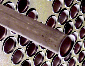
Sleeving consists of expanding thin tubes (sleeves) into the tubes of a heat exchanger. The expanding process produces a residual, interfacial fit pressure between the outside surface of the sleeve and the inside surface of the tube. The sleeves may be short, for instance about 6 to 16 in., or may extend for the full straight length of the tubes. Typical sleeve thicknesses are 0.01 to 0.03 in., depending upon material of construction and thickness of the original tubes. In addition to the expansion step, sometimes the inner end of the sleeves is welded to the inside wall of the tube.
In tubular heat transfer equipment in power plants, sleeving has long been used for one or more of these purposes:
- To reduce the prospect of inlet-end tube erosion (short sleeves for this purpose are also called ferrules, and their use is called ferruling)
- To restore tubes to service that had been plugged by plant personnel because of known perforations in discrete, identifiable locations
- To restore tubes to service that had been plugged because their walls had become excessively thin
- To bridge failures in discrete locations of tubes that are otherwise intact; for example, if a tube has a circular crack just beyond the inner face of the tubesheet
Related Topics

Labels: Heat Exchanger, Life, Sleeving
Thursday, September 27, 2007

Related Topics

Labels: Heat Exchanger, Heat Transfer
Wednesday, September 26, 2007
It extended to pumping liquid from one tank / drum to another tank /drum. It elaborate quite a lot on the pump head-capacity curve and interaction with piping resistance curve. the best features in this article is the STEP-by-STEP of pump hydraulic calculation, available Net Positive Suction Head (NPSHa) determination. This typical form the basis for a pump specification. A process engineer MUST read this and familiar with pump hydraulic.
Apart it also discuss the affinity law, selection guidelines for centrifugal & reciprocating pumps, pump protection methodology, etc.
Related Topics :

Labels: Design, Hydraulic, Piping
Monday, September 24, 2007

Related topics :
Labels: Design, Hydraulic, Piping
Thursday, September 20, 2007

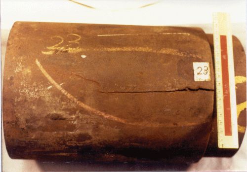
High temperature gas contain Hydrogen is compressed and fed to furnace and reactor. Heating and reaction taken place in the furnace and reactor and hot product is fed to a separator. Pressure Relief Valve protecting compressor is bypassed the furnace and reactor and connected to downstream of furnace and reactor. Generally the is no flow passing the Pressure Relief Valve discharge and is expected the discharge piping is always under low temperature. Those High temperature hydrogen attack is not expected in the Pressure Relief Valve discharge piping and design has not considered it.
After the incident, investigation has reported that the burst piping is caused by High Temperature Hydrogen Attack. How the piping is exposed high temperature and how the hydrogen can get into this piping ?
If you review details drawing in figure 4 in the report, you will find that the piping burst at the location closed to the main pipe. During normal operation, hot gas is flowing through the main pipe and main pipe is heated to high temperature. Hot main pipe will transmit heat to the branch from Pressure relief Valve with conduction effect. Temperature is gradual reduced with distance from the branch tie-in.
In the event compressor is overpressure, pressure relief valve popped will release high temperature gas with hydrogen rich in it. Whenever it passing through the pipe, hot piping metal will pick-up the hydrogen, react with Carbon in the piping and form Methane and this will weaken the hot carbon steel piping.
One note has not been addressed is that there is residue hydrogen gas in the product line. This continuously expose the branch with hydrogen. Hydrogen pick-up activity is continues during normal operation.
Lesson here is never under-estimated Hydrogen attack in metal and alloy. Whenever dealing with hydrogen, special attention shall be taken for those non- continuous operating lines.
Related reading
- High Temperature Hydrogen Attack in metal & alloy
- Hydrogen Embrittlement TEST method
- Hydrogen present and it's impact to metallurgy
- Different Equation for Pitting Resistance Equivalent Number (PREN)
- Chlorride stress corrosion cracking and use of correct MOC for seawater
- Pitting Corrosion - Mechanism & Prevention
Labels: Accident, Corrosion, Corrosion Resistance Material, Material
Tuesday, September 18, 2007
This is another of excellent workbook related to Emergency Relief System recommends to those engineer who works (design, engineering, operation) in Oil & Gas platform, Chemical & Process plant, Refinery, Chemical plant, etc. Again in particular for SAFETY & LOSS PREVENTION engineer...

Workbook for Chemical Reactor Relief System Sizing
The workbook is to provide information on methods available for the sizing of emergency relief systems for exothermic runaway reactions in liquid-phase chemical reactions. This work mainly written for SAFETY & LOSS PREVENTION engineers who are dealing with Chemical relief with reaction and shall have good basic experiences in Chemical reaction Kinetics and fluid flow.
This workbook is available FREE for download from HSE UK.
Related topics
- A must have book...Emergency Relief System Design Using DIERS Technology
- Requirement of overpressure protection devices on system design to PIPING code
Labels: Ebook, Emergency Relief System, Loss Prevention, Safety
Sunday, September 16, 2007


Part of the PREFACE...
- Direct empirical scaling of experimental data obtained in vessels witha very lower thermal inertia.
- Semi-theoretical graphical or analytical design methods.
- Computer simulation of incidents and flow through relief systems.
- to provide a record of the DIERS research project.
- to help organizations acquire, assimilate and implement the vastamount of DIERS information and technology by serving as both areference and training tool.
- to illustrate ERS design methodology by means of selected sampleproblems.
- to serve as a text for the AIChE/DIERS Continuing EducationCourse entitled "Emergency Relief System Design Using DIERS Technology."
Related reading
Labels: Emergency Relief System, Loss Prevention, Safety
Saturday, September 15, 2007
Friday, September 14, 2007
The methane forms and stays in grain boundaries and voids however it does not diffuse out of the metal. Once it accumulated in the grains and voids, it expands and forms blister , weaken the metal strength and initiate cracks in the steel.
High-strength low-alloy steels are particularly susceptible to this mechanism, which leads to embrittlement of the bulk parent metal (typical C-0.5 Mo steels). The embrittlement in the material can result in a catastrophic brittle fracture of the asset.
Following is a picture of Blistering in metal due to High Temperature Hydrogen Attack.
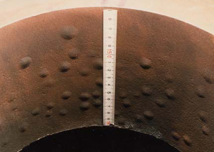
"Exisitng C-0.5Mo steel in hydrogen service is still our concern in industries. High Temperature Hydrogen Attack (HTHA) has been one of the major problems in petroleum and petrochemical industry because of its effect. Since the original Nelson Curves was suggested in 1949 to define the operating limits for steels used in hydrogen service to avoid HTHA, a number of research and investigation activities on HTHA have been carried out mainly in The United States and
Related reading
- Hydrogen Embrittlement TEST method
- Hydrogen present and it's impact to metallurgy
- Different Equation for Pitting Resistance Equivalent Number (PREN)
- Chlorride stress corrosion cracking and use of correct MOC for seawater
- Pitting Corrosion - Mechanism & Prevention
Labels: Corrosion, Corrosion Resistance Material, Material
Thursday, September 13, 2007
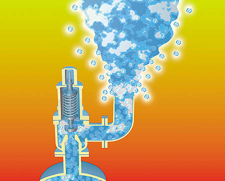
 There are some confusion or argument if over perssure protection devices e.g. Pressure Relief Valve, rupture disc, etc, shall be provided on a pressure containing part which designed to PIPING code i.e. ASME B31.3.
Above statement may be true :
- if the INVENTORY capture in the system is LOW and associated RISK is LOW.
- if the system is TOTALLY FREE from overpressure scenario i.e. external fire, solar heating, etc. For example buried pipeline.
Requirement of PSV shall NOT be 100% judged from the design code itself. The RISK and CONSEQUENCE e.g. INVENTORY associates risk & consequences shall come into consideration to define if a overpressure protection i.e PSV is required.
Good engineering practices such as SHELL DEP 80.45.10.10-Gen, section 2.2.2, has provision of waiver of overpressure protection if made-of small inventory (<500 Liters), containing non-toxic fluid and fluid initial boiling point is higher than maximum ambient temperature.
Related reading
Labels: Code, Overpressure Protection, Pressure Relief Device
Wednesday, September 12, 2007
 In earlier post << DISTILLATION : Alcohol Distillation >> and << World Class Home Distillation >>, I have recommended some information on Making of Alcohol for those who are interested...
Labels: Distillation
Monday, September 10, 2007

Standard Test Methods (NACE, ASTM)
- NACE TM0177 - laboratory testing of metals for resistance to sulfide stress cracking in H2S environments.
- NACE TM0284 - evaluation of pipeline and plate steels for resistance to stepwise cracking.
- ASTM G129 - slow strain rate test for determination of environmentally assisted cracking.
- ASTM G142 - tension tests in hydrogen environments.
- ASTM G146 - hydrogen induced disbonding of stainless clad steel plate in refinery hydrogen service.
- ASTM F-326 - method for electronic hydrogen embrittlement test for cadmium electroplating processes.
- ASTM F-519 - method for mechanical hydrogen embrittlement testing of plating processess and aircraft maintenance chemicals.
- ASTM A-143 - practice of safeguarding against embrittlement of hot dip galvanized structural steel products and detecting embrittlement.
- ASTM B-577 - hydrogen embrittlement of deoxidized and oxygen free copper.
Some guidelines for use of test methods :
- General purpose - Slow strain rate test methods. Conservative results is expected.
- High strength material - Constant load test method
- Low strength material - Non-stressed coupons exposed to testing fluid
- Material exposed to Hydrogen environment at high temperature - Special testing to be handled by specialist.
- Hydrogen present and it's impact to metallurgy
- Different Equation for Pitting Resistance Equivalent Number (PREN)
- Chlorride stress corrosion cracking and use of correct MOC for seawater
- Pitting Corrosion - Mechanism & Prevention
Labels: Corrosion, Corrosion Resistance Material, Material
Sunday, September 9, 2007

In one of the field development project, the feed composition contain trace amount of hydrogen (H2). What extra pre-cautions that we needs to take care as compare to other hydrocarbon gases? One of the problems that shall always be taken care is Hydrogen embrittlement and material selection.
What is H2 embrittlement ?
H2 embrittlement is the embrittlement of metal or alloy involves hydrogen ingression in to metal or alloys matrix and significantly decrease it’s ductility (ability to deform), cause metal or alloys crack and catastrophic failure at stresses below normal yield stress level of the attacked material.
How H2 cause metal or alloys lose it ductility ?
Whenever metal or alloys expose to fluid contains hydrogen, hydrogen will dissolved in solid metal to give up it electrons to metal and form hydrogen nucleus which is very small. Small nucleus hydrogen will stay in the metal or alloys matrix, it probably will meet with another nucleus hydrogen and combine and form molecule Hydrogen. Molecule Hydrogen will expand and cause metal or alloys cracking in micro scale. This partially reduce it tensile strength. Expansion of molecule Hydrogen in metal or alloys matrix will displaced it metal further and decrease its ductility.
How H2 is introduce into metal or alloy matrix ?
Hydrogen can be introduced into metal or alloy :
- manufacturing & making of metal or alloy
- welding
- contact with fluid contains hydrogen
- electroplating
- cathodic protection
- rusting (corrosion)
- phosphating
- pickling
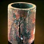
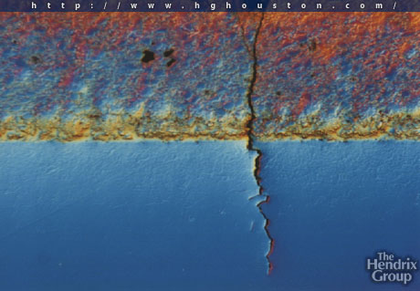
Metal cracking cause by H2 embrittlement
Following are some images shows cracking caused by h2 embrittlement.
How to minimize or avoid H2 embrittlement ?
There are number of ways to minimize or avoid H2 embrittlement :
a) minimize amount of residual H2 in metal or alloy during fabrication
- Cleaning, preheating, keep dry during welding
- avoid rapid heating and cooling
- Post Weld Heat Treatment of metal or alloy
b) minimize amount of H2 pick up by metal or alloy during operation
- avoid using chemical or additive generating H2
c) Use high resistance to H2 embrittlement material e.g. aluminium, plastic, etc
d) Use low strength metal or alloy
e) Use plating or coating process with low or no hydrogen generation
Further reading
- Different equation for Pitting Resistance Equivalent Number (PREN)
- Chloride stress corrosion cracking and use of correct MOC for seawater
- Pitting corrosion - Mechanism & Prevention
- Hydrogen Embrittlement : A guide for the metal finisher
- Hydrogen embrittlement : How Small Details Can Have Large Effects
Labels: Corrosion, Corrosion Resistance Material, Material
Thursday, September 6, 2007
As this unit will be installed on existing platform, space and weight constraint are the MAJOR issues. Many efforts have been implemented in order to reduce new installation space and weight. One of them is to reduce the Lube Oil Cooler Size.
Turbulator
The following image demonstrates a wire matrix turbulator by hiTRAN
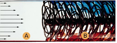
Wire matrix turbulator, known as a HiTRAN® Matrix Element, is inserted into inner tube of Heat Exchanger. The basic principle is to promote fluid mixing, convert laminar flow to turbulence flow pattern, maintaining turbulence flow pattern and improve tube-side heat and mass transfer.
From above image,
- region (A) is laminar flow conditions
- region (B) is turbulence caused by the use of hiTRAN matrix tube Inserts
See below the comparison between Compressor lube oil cooler (Air-Cooled Heat Exchanger) with and without turbulator :
Number of tube rows above each other 5* (with turbulator) 10* (without turbulator)
Width 4* m(with turbulator) 7.3* m (without turbulator)
Length 7.9* m (with tubulator) 12.2* m (without turbulator)
Height 7.2* m (with turbulator) 9.3* m (without turbulator)
* For reference only
Turbulator has significantly reduce the space consume and weight and it ensure the project to proceed to installation phase. Idea of using turbulator is one of the success story in debottlenecking project especially those have space and weight constraints.
Further Reading
Labels: Air Cooler, Heat Exchanger
Tuesday, September 4, 2007
Labels: Acid Gas Removal, gas processing, Gas Sweethening
