Monday, June 30, 2008
Display problem ? Click HERE
Recommended :
Subscribe FREE - Plant Services
 A stream or unit operation has been properly defined in a HYSYS file (i.e. ABC.hsc), you would like to copy and transfer complete information to another HYSYS file (i.e. 123.hsc), a tedious way is the print the Datasheet of the stream or unit operation with all information (in ABC.hsc) and key in the same information in 123.hsc. This is rather time consuming and potentially expose to typo error.
Subscribe FREE - Plant Services
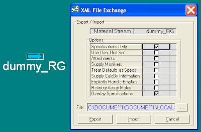
A stream or unit operation has been properly defined in a HYSYS file (i.e. ABC.hsc), you would like to copy and transfer complete information to another HYSYS file (i.e. 123.hsc), a tedious way is the print the Datasheet of the stream or unit operation with all information (in ABC.hsc) and key in the same information in 123.hsc. This is rather time consuming and potentially expose to typo error.HYSYS has a special feature (if you have not know about it) is the XML Data Exchange. It help to extract information of a stream or unit operation into a temporary file (UnitOp.XML) and allow other file can access the information in this XML file.
For example, you would like to transfer stream information (i.e. Rich gas in ABC.hsc) into a stream (i.e. dummy_RG in 123.hsc).
Step 1 : Open ABC.hsc file
Step 2 : Put the pointer ("cross lines") on the Rich Gas stream.
Step 3 : Right Click, follow by clicking on the XML Data Exchange. XML file Exchange sheet will be displayed.

Step 4 : Click Export. All information from Rich Gas stream will be transferred into UnitOp.XML

Step 5 : Open the new file (123.hsc) and create a new stream dummy_RG
Step 6 : Put the pointer ("cross lines") on the dummy_RG stream
Step 7 : Right Click, follow by clicking on the XML Data Exchange. XML file Exchange sheet will be displayed.
Step 8 : Click Import. All information from UnitOp.XML stream will be transferred into dummy_RG.
Above method may apply to other unit operation like separator, pump, etc. It save a lot of simulation time when you are handling many streams in many files.
Related Topic
- A Great Material In Traininig Young Engineer in HYSYS
- Useful Documentation for HYSYS ...
- Properly Simulate a Separator with Demister in HYSYS
- What to do if HYSYS 3.2 Can not Locate License Server ?
- Lesson Leaned from Installation of SHELL FRED
- Bug in ASPENTECH HYSYS 2006 Dynamic Depressuring Fisher Valve model
- How to apply valve equation in HYSYS Depressuring ?
Labels: HYSYS
Sunday, June 29, 2008
Display problem ? Click HERE
Recommended :
Subscribe FREE - Plant Services
In earlier post "FAYF - Acid Solution Storage", Carbon Steel (CS) may be used for concentrated Sulfuric acid (H2SO4) at ambient temperature. However, diluted H2SO4 may severely corrodes CS. Non-metal material (PVC, PFA, FEP, PTFE) may be used for concentrated and diluted H2SO4 solution. Nevertheless, these materials lose it strength at high temperature and high pressure operation. Using non-metal material may not be cost effective at high temperature and high pressure design.
Thus for high temperature and high pressure operation, exotic material Zirconium and its alloy may be considered.
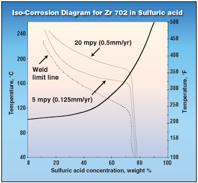
Zirconium has excellent corrosion resistance in all concentrations of sulfuric acid up to 70% and well above boiling.
Zirconium Limitation and its work-around...
 H2SO4 concentration exceeded 55%, there will be preferential corrosion attack at weld. WIth H2SO4 concentration exceeded 65%, there may be Sulfide Stress Corrosion Cracking (SSCC) in Zirconium. Thus, stress-relief anneal (heat treatment) should be conducted to avoid above mentioned preferential corrosion and SSCC. However, In the presence of fluoride ions, Zirconium should not be used with sulfuric acid.
For H2SO4 concentration exceeded 70%, other material such as Tantalum may be considered. Tantalum can take any H2SO4 concentration with temperature upto 200 degC.
Read more details explanation in
Note :
*This article is only available FREE to Chemical Engineering Magazine registered user.
Login required. Registration FREE (Click HERE).
** Download immediately as article available FREE within short period (JUNE 2008 only)
*** Found lost link or unable to download, may contact me...
RELATED POST
Subscribe FREE - Plant Services
In earlier post "FAYF - Acid Solution Storage", Carbon Steel (CS) may be used for concentrated Sulfuric acid (H2SO4) at ambient temperature. However, diluted H2SO4 may severely corrodes CS. Non-metal material (PVC, PFA, FEP, PTFE) may be used for concentrated and diluted H2SO4 solution. Nevertheless, these materials lose it strength at high temperature and high pressure operation. Using non-metal material may not be cost effective at high temperature and high pressure design.Thus for high temperature and high pressure operation, exotic material Zirconium and its alloy may be considered.
Zirconium has excellent corrosion resistance in all concentrations of sulfuric acid up to 70% and well above boiling.
Zirconium Limitation and its work-around...
H2SO4 concentration exceeded 55%, there will be preferential corrosion attack at weld. WIth H2SO4 concentration exceeded 65%, there may be Sulfide Stress Corrosion Cracking (SSCC) in Zirconium. Thus, stress-relief anneal (heat treatment) should be conducted to avoid above mentioned preferential corrosion and SSCC. However, In the presence of fluoride ions, Zirconium should not be used with sulfuric acid.For H2SO4 concentration exceeded 70%, other material such as Tantalum may be considered. Tantalum can take any H2SO4 concentration with temperature upto 200 degC.
Read more details explanation in
Note :
*This article is only available FREE to Chemical Engineering Magazine registered user.
Login required. Registration FREE (Click HERE).
** Download immediately as article available FREE within short period (JUNE 2008 only)
*** Found lost link or unable to download, may contact me...
RELATED POST
- FAYF - Acid Solution Storage
- High Temperature Hydrogen Attack in metal & alloy
- Hydrogen Embrittlement TEST method
- Hydrogen present and it's impact to metallurgy
- Different Equation for Pitting Resistance Equivalent Number (PREN)
- Chlorride stress corrosion cracking and use of correct MOC for seawater
- Pitting Corrosion - Mechanism & Prevention
Labels: Corrosion Resistance Material, Material
Saturday, June 28, 2008
Display problem ? Click HERE

This following reading material has been introduced by Ahmad, a fresh chemical engineer and oyal reader of Chemical & Process Technology. Thanks Ahmad.
HYSYS : An introduction to Chemical Engineering Simulations is intended for student who are using HYSYS for th first time and have a little or no experience in computer simulation. It can be used as a textbook in any chemical engineering courses, workshop, etc. The book can be served as reference in more advanced chemical engineering courses when HYSYS is used as tool for simulation for problem solving. It also used as supplement to assist training of young engineers. It was written by Engr. Mohd Kamaruddin Abd. Hamid from Universiti Technology Malaysia (UTM), one of the famous Higher Education Study in Malaysia.
My 2 cents comments
This book is rather a good beginning for a freshman in learning HYSYS and a good reference material for a young engineer. Those small organizations with limited budget in training can utilize this book as a material for their young engineer training purpose.
There are substantial HYSYS reference in "Useful Documentation for HYSYS ...". This post will be updated from time to time with the inclusion of contributions by all loyal readers and visitors of Chemical & Process Technology.
Thanks to Ahmad.
Related Topic
- Useful Documentation for HYSYS ...
- Properly Simulate a Separator with Demister in HYSYS
- What to do if HYSYS 3.2 Can not Locate License Server ?
- Lesson Leaned from Installation of SHELL FRED
- Bug in ASPENTECH HYSYS 2006 Dynamic Depressuring Fisher Valve model
- How to apply valve equation in HYSYS Depressuring ?
Labels: HYSYS
Thursday, June 26, 2008
Display problem ? Click HERE
Recommended :
Subscribe FREE - Plant Services
Liquid is known as "incompressible" fluid. When it is trapped or blocked with heat input, liquid expansion with with insufficient room for expansion or release, the internal pressure exerted on liquid container i.e. pipe, vessel, etc would increases quickly. This is known as hydraulic expansion thermal relief which potentially leads to piping or equipment fail catastrophically.
Subscribe FREE - Plant Services
Liquid is known as "incompressible" fluid. When it is trapped or blocked with heat input, liquid expansion with with insufficient room for expansion or release, the internal pressure exerted on liquid container i.e. pipe, vessel, etc would increases quickly. This is known as hydraulic expansion thermal relief which potentially leads to piping or equipment fail catastrophically.Vessel or other pressure contained compartment to industrial accepted code such as ASME, JIS, DIN, GB, etc. These codes would request pressure relief device i.e. pressure relief valve (PRV) to protect the vessel or pressure contained compartment from overpressure scenario including hydraulic expansion thermal relief. Nevertheless, the piping design code i.e. ASME does not request pressure relief device and it subject to analysis and justification.
There are several aspects shall be considered to analyze and judge if thermal relief is required :- Heat source & heat input rate
- Liquid properties
- Trapped volume & pressure level
- System tightness & leakage
- Blocking-in probability and safe procedure
- other means of thermal relief
There are several potential heat sources :
- Hot fluid or heating medium in heat exchanger or heater
- Heating fluid in Jacketed / Coiled Vessel
- Reactor (exothermic reaction ) with cooling medium in jacket
- External fire
- Heat tracing by heating medium or electricity
- Ambient heat input (due to hot environment i.e. coal boiler house)
- Solar radiation
Item (5) has lower potential in high heat input as compare to item (1) to (4). High availability and reliability safeguarding device shall be provided in order to eliminate the potential of liquid expansion and thermal relief. In many event, providing a small DN15x20 PSV is much cost effective than providing other safeguarding measures.
Item (6) and (7) have least potential in high heat input. If the system can be buried, shielded, painted with white or metallic paint to reflect solar radiation, or efficiently insulated to minimise heat gain, the requirement for thermal relief can probably be eliminated. Again, in many event, providing a small DN15x20 PSV is much cost effective than providing other safeguarding measures.
Trapped Liquid Properties
 Those liquid trapped or blocked in is flammable, low boiling point including cryogenic type, volatile and toxic are regarded high potential liquid expansion and high risk liquid group. Thermal relief is always required however subject to trapped volume quantity, likelihood of liquid trapped event, risk to human, etc. Low risk liquid such as water, solar radiation heat input is very unlikely to create a safety hazard. Nevertheless, for long pipeline with large volume liquid, there is still a potential liquid expansion lead pipeline failure.
Trapped volume & Pressure Level
Trapped volume and pressure level links to risk and hazard level. Large the trapped volume and higher the pressure level, the higher the risk and hazard level to human and surrounding and a thermal relief protection is required.
Blocking-in probability and safe procedure
A system normally in flowing condition and will only be blocked in during maintenance period, a safe administrative procedure is implemented to ensure no trapped liquid during blocked in condition, it can be acceptable not to consider liquid expansion lead to catastrophe failure. This is inline with API Std 521, 2007. Nevertheless, special cases such as long pipeline and large vessel & exchanger and safety analysis shows the probability is reasonably high, a detail calculation and analysis is required to justify requirement of PSV for thermal relief.
System tightness & leakage
A small leakage across valve, flanges and fittings would significant reduce the likelihood of overpressure due to liquid expansion. However, the leakage via these device may be guaranteed the leakage rate and failed to justify in quite a lot of similar event.
Other means of thermal relief
Present of other means of relief such a control valve, high reliability device, etc would reduce the likelihood of liquid expansion.
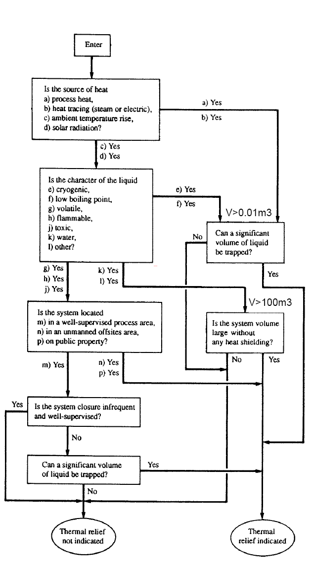
Following is flow chart can be used to helps any engineer to determine if a thermal relief PSV is required.
Above flow chart is a tool to assist engineer to make a quick check if a thermal relief PSV is required. However, it does not cover risk level for all scenario. Using this flowchart with a sound engineering judgment and analysis shall be implemented simultaneously.
Related Post
Item (6) and (7) have least potential in high heat input. If the system can be buried, shielded, painted with white or metallic paint to reflect solar radiation, or efficiently insulated to minimise heat gain, the requirement for thermal relief can probably be eliminated. Again, in many event, providing a small DN15x20 PSV is much cost effective than providing other safeguarding measures.
Trapped Liquid Properties
Those liquid trapped or blocked in is flammable, low boiling point including cryogenic type, volatile and toxic are regarded high potential liquid expansion and high risk liquid group. Thermal relief is always required however subject to trapped volume quantity, likelihood of liquid trapped event, risk to human, etc. Low risk liquid such as water, solar radiation heat input is very unlikely to create a safety hazard. Nevertheless, for long pipeline with large volume liquid, there is still a potential liquid expansion lead pipeline failure.Trapped volume & Pressure Level
Trapped volume and pressure level links to risk and hazard level. Large the trapped volume and higher the pressure level, the higher the risk and hazard level to human and surrounding and a thermal relief protection is required.
Blocking-in probability and safe procedure
A system normally in flowing condition and will only be blocked in during maintenance period, a safe administrative procedure is implemented to ensure no trapped liquid during blocked in condition, it can be acceptable not to consider liquid expansion lead to catastrophe failure. This is inline with API Std 521, 2007. Nevertheless, special cases such as long pipeline and large vessel & exchanger and safety analysis shows the probability is reasonably high, a detail calculation and analysis is required to justify requirement of PSV for thermal relief.
System tightness & leakage
A small leakage across valve, flanges and fittings would significant reduce the likelihood of overpressure due to liquid expansion. However, the leakage via these device may be guaranteed the leakage rate and failed to justify in quite a lot of similar event.
Other means of thermal relief
Present of other means of relief such a control valve, high reliability device, etc would reduce the likelihood of liquid expansion.
Following is flow chart can be used to helps any engineer to determine if a thermal relief PSV is required.
Above flow chart is a tool to assist engineer to make a quick check if a thermal relief PSV is required. However, it does not cover risk level for all scenario. Using this flowchart with a sound engineering judgment and analysis shall be implemented simultaneously.
Related Post
- Why Rupture (RD) Upstream of Pressure Relief Valve (PRV) ?
- Why Two Rupture Discs in Series ?
- Tube Rupture : Pressure Relief Valve (PSV) or Rupture Disk (RD) ?
- Criteria for Requirement of Pressure Relief Device for Tube Rupture
- Some Comments on Providing External Insulation as Protective Measure against FIRE
- Protective Measures against FIRE other than Pressure Relief Device (PRD)
- Design Temperature (Td) versus Maximum Allowable Working Temperature (MAWT)
- PSV for Shell-and-Tube HEX Tube Side Overpressure Protection against External Fire Attack ?
Labels: Overpressure Protection, Pressure Relief Device
Wednesday, June 25, 2008
Display problem ? Click HERE

Simple update to IEM Members or those who are practicing Engineering in MALAYSIA...
I received a notification from IEM that there will be a series of interesting events for JUNE & JULY 2008...
Visit to HUME Concrete Marketing S/B
- 28 June 2008, Saturday (4 CPD)
- 8.30 a.m. to 1.00 p.m
- Participants are to assemble at Bangunan Ingenieur before 8.00 a.m.
- Fees :RM 30.00 - transportation of the site tour
Hume Concrete Marketing Sdn Bhd is the marketing arm of Hume Concrete Division, which in turn is one of the strategic business units of Hume Industries (M) Berhad. The first Hume precast concrete factory was established in Prai way back in 1929. From this humble beginning, Hume Concrete Division has grown to be the premier manufacturer of precast concrete products, with 5 main factories strategically located throughout Malaysia, to cater for both local and export markets. Hume is the pioneer in introducing the standard range of precast products such as Spun Pipe, Prestressed Beam, RC Pile, U-Drain, Box Culvert, etc. into the local market. With accumulated experience and commitment towards R & D, we have in recent years developed a range of innovative products such as Hume Box Girder, Hume Arch Culvert, Hume Half Slab, Hume T-Wall, Hume S-Barrier and Hume Stadium Bleacher, to name a few. Hume is also the Licensee of BEBO range of arch crossings from BEBO Arch International AG, Switzerland. Furthermore, Hume has built up a strong technical team to offer customized precast solutions to meet specific needs of individual clients, especially in the field of precast jetty component.
Prepared by Engr. K P Pradeep, M.I.E.M, PEng
Talk on "Evolution of the Distributed Control System (DCS)"Prepared by Engr. K P Pradeep, M.I.E.M, PEng
- 11 July 2008, Friday (2 CPD) - 2nd Floor, IEM Conference Hall
- 5.30 pm to 7.30 pm
- 2 nd Floor, IEM Conference Hall, Bangunan Ingenieur, Petaling Jaya
- Speaker : Mr. Stephen Lim
In this presentation, Stephen will cover several aspects regarding the DCS. An introduction to the Distributed Control System, from what it is, what it comprises of and how it has developed throughout the decades will be shown. This will provide an outlook on the historical emergence of such a system and the ever-growing need for the DCS in the process industry. Comparisons between a Programmable Logic Controller (PLC) and a DCS will be made to show the applications and industries these systems are catered to. For the hybrid industries, we will discuss on how the Programmable Automation Controller (PAC) affects the DCS market. Other topics of this presentation will include networking and wireless technologies, process field-bus technologies, advanced process control techniques and how these have been integrated into the DCS.
Prepared by Engr. Abdul Fattah bin Mohamed Yatim, MIEM
Dialogue: "Continuing Professional Development & you an intermittent review'
- 2 August 2008, Saturday (2 CPD)
- IEM Conference Hall, 2nd Floor, Bangunan Ingenieur, PJ
- 9:00 a.m. to 11:00 a.m.
The Board of Engineers Malaysia Continuing Professional Development Program is into its fourth year running. However, in a recent small preliminary audit on the Continuing Professional Development program for the period from 2005 to through 2007, it was found that a significant number of professional engineers (> 90%) has not come to grips with the concept of
continuing professional development mandatory of licensed professional engineers. There is glaring ill-understanding on the part of the professional engineers while documenting their CPD experiences and suffice to say that it is to the extend appalling, the responses of highly educated engineering professionals to what is a simple documentation. So it is with the desire to see to it that professional members of The Institution of Engineers Malaysia do it right and keeping it simple, that this dialogue is to gauge what’s on your mind, allowing you to voice your opinions/grievances, forward suggestions that should help the CPD programs @ IEM commensurate with the requirements of the Board of Engineers Malaysia. Again, on the premise that CPD is here to stay, this dialogue is for you to say your piece, exchange opinions and gather information on how best to go about it. So don’t stay away! It pays to be a member of IEM!
Prepared by Engr. Dr. Lee Teang Shui
Labels: NEWS
Tuesday, June 24, 2008
Recommended :
Subscribe FREE - Chemical Processing
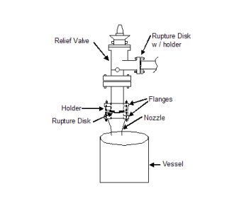
 Two main group of pressure relief devices are accepted as ultimate or final safeguarding device against overpressure protection of pressure contained equipments. There are reclosable type (pressure relief valve) and non-reclosable type (rupture disc). Both type of devices have been used in different application with their special reclosable and non-reclosable characteristic. Nevertheless, in some application, rupture disc (RD) and pressure relief valve (PRV) are use in combination. They have been applied such that RD is located upstream of PRV.
Subscribe FREE - Chemical Processing
Two main group of pressure relief devices are accepted as ultimate or final safeguarding device against overpressure protection of pressure contained equipments. There are reclosable type (pressure relief valve) and non-reclosable type (rupture disc). Both type of devices have been used in different application with their special reclosable and non-reclosable characteristic. Nevertheless, in some application, rupture disc (RD) and pressure relief valve (PRV) are use in combination. They have been applied such that RD is located upstream of PRV.What is the main purpose and advantages by placing RD upstream of PRV ?
To answer this question, it can be answered from several aspects :
- Safety
- Environment
- Cost
Equipment with fluid contain particles, solid, substances may freeze, crystallize & polymerize, etc, these substances potential stay and stick to the nozzle and PSV inlet pipe. It potentially lead to reduced flow path area and reduce flowing capacity of the relief flow path. Reduced flow would lead to overpressure and catastrophe event. Apart, reduced flow path increases inlet line frictional lose (more than 3% of set pressure) and potentially cause PSV chattering and damage. Providing RD upstream of PRV would avoid these substances accumulate at the inlet nozzle and pipes.
Prevent Opening of PRV (Safety)
As solid substance can contacts with PRV disc and seat, it may stick to the disc and seat and solidify. Sticked substance may prevent PRV from opening or increases force (pressure) to open the PRV. This potentially cause internal pressure exceeded Maximum Allowable Working Pressure (MAWP) of the protected equipment and lead to catastrophe event. Providing RD upstream of PRV would avoid these substances contact with PRV's disc and seat.
PRV "Slow" Action (Safety)
This has been discussed in "Tube Rupture : Pressure Relief Valve (PSV) or Rupture Disk (RD) ?". In the event liquid in Low Pressure Side (LPS), sudden tube rupture may generate a huge surge pressure to the LPS within a mili-second and results the intermittent peak pressure exceeded design pressure of LPS, pressure relief valve (PRV) is NOT recommended in this case. Pressure relief valve is known to be a “slow acting device”, it may NOT response fast enough to relieve pressure. Thus, a rupture disk which known as “quick acting device” is always recommended in this case.
 PRV Passing / Leaks (Environment & Health)
PRV passing and leaks is one of the common phenomenon and difficult to avoid. Continuous leaking toxic substances to atmosphere would lead to pollution (environment issue) and contact with human (health issue). Providing a RD could prevent continuous leakage.
Corrosive Fluid Corrode PRV (Capital Cost)
Corrosive fluid contact with PRV would required a Corrosion Resistance Material (CRA) PRV. It will be less expensive with corrosion resisted (CRA) RD and non-corrosion resisted (non-CRA) PRV.
Longer Overhaul/Maintenance Period (Maintenance Cost)
As fluid is not in contact with PRV (with RD upstream), the PRV is considered rather "clean" and "new". Thus, a longer period of between each Overhaul/maintenance can be extended. This indirectly reduce maintenance cost.
Extended PRV Life Span (Maintenance Cost)
Similar to above, fluid is not in contact with PRV, the PRV is considered rather "clean" and "new" and life span of PRV is extended.
Extended PRV Life Span (Maintenance Cost)
Similar to above, fluid is not in contact with PRV, the PRV is considered rather "clean" and "new" and life span of PRV is extended.
Thus, RD / PSV combination in many events could increase safety and reduce environment impact and cost.
Related Post
- Why Two Rupture Discs in Series ?
- Tube Rupture : Pressure Relief Valve (PSV) or Rupture Disk (RD) ?
- Criteria for Requirement of Pressure Relief Device for Tube Rupture
- Some Comments on Providing External Insulation as Protective Measure against FIRE
- Protective Measures against FIRE other than Pressure Relief Device (PRD)
- Design Temperature (Td) versus Maximum Allowable Working Temperature (MAWT)
- PSV for Shell-and-Tube HEX Tube Side Overpressure Protection against External Fire Attack ?
Labels: Corrosion Resistance Material, Overpressure Protection, Pressure Relief Device
Monday, June 23, 2008

Subscribe FREE - Chemical Processing
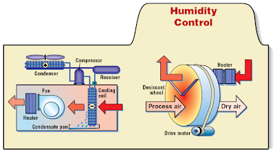
Chemical Engineering JUNE 2008 release has shared a new FAYF. This FAYF is related to some tips on Dehumidification.
What is Dehumidification ?
Chemical Engineering JUNE 2008 release has shared a new FAYF. This FAYF is related to some tips on Dehumidification.What is Dehumidification ?
Dehumidification is a process to reduce the level of humidity in air to a level for good health, cleanliness and preserve structure & quality of material.
Why dehumidify air ?
Human health - As humid air can cause mold and mildew to grow inside homes, it potentially increases human health risks.
Why dehumidify air ?
Human health - As humid air can cause mold and mildew to grow inside homes, it potentially increases human health risks.
Prevent moisture regain
- Dried food such as rice, bread, etc are dry in nature to maintain it structure, avoid mold growth and low decaying process, . Maintaining moisture in air prevent dry food becoming wet.
Prevent condensation - Moisture in are contact with cold surface like refrigerant pipe, fridge, etc would cause condensation.
Prevent corrosion - Condensed water on metal surface would promote corrosion.
Drying - Dried air can be used to reduce moisture content in product.
How air is Dehumidify ?
Three methods are common used in dehumidifying. There are :
(i) Cooling
- Cool air below dew point and moisture in the air is condensed and drained out.
How air is Dehumidify ?
Three methods are common used in dehumidifying. There are :
(i) Cooling
- Cool air below dew point and moisture in the air is condensed and drained out.
(ii) Adsorption
- Humidity is reduced with an adsorbent material as silica gel or activated alumina. Adsorption is a physical process where moisture is condensed and kept in material. Adsorbent material can be reactivated by passing hot gas.
(iii) Absorption
- Humidity is reduced with an absorbent material such as calcium chloride solution. Absorption involves a change in the physical or chemical structure of the material.
In this FAYF, only Cooling and Adsorption process are discussed.
In addition, the FAYF briefly compare the advantages and disadvantages of Cooling and Adsorption process. Basically cooling is economic and consider when dew pointing level is not that stringent. Adsorption process is used when a very dry air is required.
Read more in...
FAYF - DEHUMIDIFIER
(Click here*)
(Click here*)
Note :
*This FAYF is only available FREE to Chemical Engineering Magazine registered user. Login required. Registration FREE.
** Download immediately as article available FREE within short period (JUNE 2008 only)
*** Found lost link or unable to download, may contact me...
Technology
** Download immediately as article available FREE within short period (JUNE 2008 only)
*** Found lost link or unable to download, may contact me...
Technology
- FAYF - Acid Solution Storage
- FAYF - Flowmeter selection in brief...
- FAYF - TIPS on Heat Transfer Fluid
- FAYF - Heat Transfer - Useful Heat Transfer Equation
- OGT - Others FREE articles related to Amine & CO2...
- Optimized Gas Treating, Inc. (OGT) - Experts in CO2-Amine
- GTC - Technology Provider for naphtha processing to terephthalic acid purification
Labels: Absorption, Adsorption, Corrosion, Heat Transfer
Sunday, June 22, 2008
Display problem ? Click HERE

A vessel with liquid at it boiling point exposing to external heat input from Fire would lead to liquid vaporization. Vaporization would subsequently leads internal pressure increases upto Pressure Relieve Valve (PRV) set pressure. The PRV will starts to open to relieve part of the vapor in order to maintain the vessel internal pressure within maximum allowable accumulated pressure (121% of PRV set pressure if the Vessel is designed to ASME Section VIII).
Determination of Relieve load for boiling liquid would required latent heat of the boiling liquid in the vessel. Dealing with single component, the latent heat can be easily obtained from literature or HYSYS simulator. However, in real world system, the fluid could be a multi-component fluid which the latent heat will change from initial boiling point (IBP) for final boiling point (FBP). In addition, light component with lower latent heat and lower molecular weight will release first as compare to heavy component with higher latent heat and higher molecular weight. Latent heat change lead to different relieve load and different properties would result different relieving area. Those a rigorous method may required to determine maximum relieving area. Following are the steps can be used to determine the latent heat and maximum relieving area.
HYSYS snapshot below may be referred when running through the steps.

STEP 1 : Define fluid in the vessel is at maximum Operating pressure (P0) & operating temperature (T0) prior to fire start.
HYSYS : Stream 1 is at P0 & T0. Flash stream 1 in VESSEL V-100 and associate vapor and liquid outlet are stream 2 & 3.
STEP 2a : Determine liquid volume (Vl0) and vapor volume (Vv0) which will be defined by the physical vessel dimension and piping volume. Calculate liquid volume (Vl0) and vapor volume (Vv0) consider liquid level in the vessel is at maximum liquid level (L0) and piping vapor & liquid volume.
STEP 2b : Adjust the inventory (vapor mass and liquid mass) in the vessel until you achieve the vapor
volume (Vv0) and liquid volume (Vl0).
HYSYS : Copy stream 2 to stream 4. Copy stream 3 to stream 5. Mix stream 4 & 5 into stream 6. ADJUST stream 4 Mass Flow to obtain Stream 6 Vapor Actual Volumetric Flow to Vv0. ADJUST stream 5 Mass Flow to obtain Stream 6 Liquid Actual Volumetric Flow to Vl0.
STEP 3 : Bring the the system to Relieving pressure (Pr0=121% of Pset). By maintaining system volume at V0 (=Vv0+Vl0). The system is at relieving condition. The temperature at this point is Tr0.
HYSYS : Define a new stream 7 with a BALANCE unit (mole balance only). Set Stream 7 pressure at Pr0. ADJUST stream 7 temperature until Overall Actual Volumetric Flow to V0 (=Vv0+Vl0).
STEP 4 : Next step is further input heat (Q1) to achieve 1-2 deg C above Tr0 but maintain pressure at Pr0. Normally the total volume (V1) at this point potentially higher than V0.
HYSYS : Flash stream 7 in VESSEL V-101 into Vapor outlet, stream 6 and Liquid Outlet stream 11. Attach a heat stream (Q-100) into V-101. SET stream 8 temperature 1-2 degC above stream 7.
STEP 5 : Part of the vapor (m1) from the system shall be removed in order to bring the system volume (V1) back to V0 as the physical volume maintain.
HYSYS : SPLIT stream 8 into stream 9 and 10. Mix stream 9 & stream 11 form stream 12. ADJUST stream 9 Mass Flow (m1) to obtain Stream 12 Overall Actual Volumetric Flow to V0.
STEP 6 : Above has shown that m1 (stream 9) will be removed with the heat input of Q1 (Q-100) and maintaining at set pressure. Heat input is used to heat the vapor and liquid from Tro to Tr1 (sensible heat) and vaporized m1 of liquid (Latent Heat of Vaporization).
Latent Heat of Vaporization,
where
m8 - Mass of stream 8 (Vapor)
m9 - Mass of stream 9 (Removed Vapor)
m11 - Mass of stream 11 (Liquid)
Cp7 - Stream 7 (Mixed) specific heat capacity
Cp8 - Stream 8 (Vapor) specific heat capacity
Cp11 - Stream 11 (Liquid) specific heat capacity
dT = Tr0 - Tr1
STEP 7 : Determine Fire heat load input (Qc1) from API equation (Q=43.2A^0.82).
STEP 8 : Determine PSV mass flow rate with M1= m1 x (Qc1/ Q1)
STEP 9 : Calculate the Relief area (A1) base on M1 and fluid properties from stream 9.
STEP 10 : Repeat (4) - (9) until you get the maximum Relief area (Amax).
 One shall remember there are several assumptions have been considered in this method. One of them is Liquid properly disengaged from vapor and zero entrainment is assumed. Read more in "How Fluid Characteristic affect 2 phase Relief via PSV on Liquid filled Vessel Exposing to External Fire".
Above method also assumed 100% heat input from fire will be transferred to fluid. No accumulation of heat in vessel metal is considered (for conservatism). The heat transfer rate at liquid is considered perfect to allow 100% heat transfer.
The heat input into vessel exposing to vapor section, majority of the heat will stay in the metal. This is significantly reduce the vessel maximum allowable stress. Nevertheless, it was assumed the stress due to internal pressure is always lower than vessel maximum allowable stress throughout the relieving period.
Related Topic
HYSYS : Stream 1 is at P0 & T0. Flash stream 1 in VESSEL V-100 and associate vapor and liquid outlet are stream 2 & 3.
STEP 2a : Determine liquid volume (Vl0) and vapor volume (Vv0) which will be defined by the physical vessel dimension and piping volume. Calculate liquid volume (Vl0) and vapor volume (Vv0) consider liquid level in the vessel is at maximum liquid level (L0) and piping vapor & liquid volume.
STEP 2b : Adjust the inventory (vapor mass and liquid mass) in the vessel until you achieve the vapor
volume (Vv0) and liquid volume (Vl0).
HYSYS : Copy stream 2 to stream 4. Copy stream 3 to stream 5. Mix stream 4 & 5 into stream 6. ADJUST stream 4 Mass Flow to obtain Stream 6 Vapor Actual Volumetric Flow to Vv0. ADJUST stream 5 Mass Flow to obtain Stream 6 Liquid Actual Volumetric Flow to Vl0.
STEP 3 : Bring the the system to Relieving pressure (Pr0=121% of Pset). By maintaining system volume at V0 (=Vv0+Vl0). The system is at relieving condition. The temperature at this point is Tr0.
HYSYS : Define a new stream 7 with a BALANCE unit (mole balance only). Set Stream 7 pressure at Pr0. ADJUST stream 7 temperature until Overall Actual Volumetric Flow to V0 (=Vv0+Vl0).
STEP 4 : Next step is further input heat (Q1) to achieve 1-2 deg C above Tr0 but maintain pressure at Pr0. Normally the total volume (V1) at this point potentially higher than V0.
HYSYS : Flash stream 7 in VESSEL V-101 into Vapor outlet, stream 6 and Liquid Outlet stream 11. Attach a heat stream (Q-100) into V-101. SET stream 8 temperature 1-2 degC above stream 7.
STEP 5 : Part of the vapor (m1) from the system shall be removed in order to bring the system volume (V1) back to V0 as the physical volume maintain.
HYSYS : SPLIT stream 8 into stream 9 and 10. Mix stream 9 & stream 11 form stream 12. ADJUST stream 9 Mass Flow (m1) to obtain Stream 12 Overall Actual Volumetric Flow to V0.
STEP 6 : Above has shown that m1 (stream 9) will be removed with the heat input of Q1 (Q-100) and maintaining at set pressure. Heat input is used to heat the vapor and liquid from Tro to Tr1 (sensible heat) and vaporized m1 of liquid (Latent Heat of Vaporization).
Latent Heat of Vaporization,
Hvap = [Q1 - m8 x dT x (Cp7+Cp8)/2 - m11 x dT x (Cp7+Cp8)/2]/m9
where
m8 - Mass of stream 8 (Vapor)
m9 - Mass of stream 9 (Removed Vapor)
m11 - Mass of stream 11 (Liquid)
Cp7 - Stream 7 (Mixed) specific heat capacity
Cp8 - Stream 8 (Vapor) specific heat capacity
Cp11 - Stream 11 (Liquid) specific heat capacity
dT = Tr0 - Tr1
STEP 7 : Determine Fire heat load input (Qc1) from API equation (Q=43.2A^0.82).
STEP 8 : Determine PSV mass flow rate with M1= m1 x (Qc1/ Q1)
STEP 9 : Calculate the Relief area (A1) base on M1 and fluid properties from stream 9.
STEP 10 : Repeat (4) - (9) until you get the maximum Relief area (Amax).
One shall remember there are several assumptions have been considered in this method. One of them is Liquid properly disengaged from vapor and zero entrainment is assumed. Read more in "How Fluid Characteristic affect 2 phase Relief via PSV on Liquid filled Vessel Exposing to External Fire".Above method also assumed 100% heat input from fire will be transferred to fluid. No accumulation of heat in vessel metal is considered (for conservatism). The heat transfer rate at liquid is considered perfect to allow 100% heat transfer.
The heat input into vessel exposing to vapor section, majority of the heat will stay in the metal. This is significantly reduce the vessel maximum allowable stress. Nevertheless, it was assumed the stress due to internal pressure is always lower than vessel maximum allowable stress throughout the relieving period.
Related Topic
- Useful Documentation for HYSYS ...
- Extend of Pool Fire...
- How Fluid Characteristic affect 2 phase Relief via PSV on Liquid filled Vessel Exposing to External Fire
- Extra Caution When Eliminating Overpressure by Fire Attacks
- Should we consider JET FIRE for Pressure Relief Valve (PSV) load determination ?
- PSV for Shell-and-Tube HEX Tube Side Overpressure Protection against External Fire Attack ?
- Should maximum recommended wall temperature (Tw) for carbon steel vessel used as design temperature ?
Labels: Fire, HYSYS, Overpressure Protection, Pressure Relief Device
Saturday, June 21, 2008
Display problem ? Click HERE

A team from Massachusetts Institute of Technology (MIT) has recently created a new material for direct-methanol fuel cells (DMFC) which increases power output by more than 50 percent. The team used layer-by-layer assembly technique and able to creates a thin firm (nanomembrane) less permeable to methanol as compares to Nafion which presently used in the market. Read more in "MIT creates new material for fuel cells".
This significant improvement in nano technology and fuel cell industry. Fuel cell is known as one of the environment friendly energy source has obtained serious attention by many governments and high level education. This break-through probably lead nano and fuel technology to another level.
This significant improvement in nano technology and fuel cell industry. Fuel cell is known as one of the environment friendly energy source has obtained serious attention by many governments and high level education. This break-through probably lead nano and fuel technology to another level.
Labels: NanoTech
Display problem ? Click HERE
 Few years back involved in a commissioning of a gas processing plant. The process engineer hasover-estimated the pressure drop on the Deminineralized Water (DW) pump discharge line (actual pressure drop on site is much lower). Extra pressure drop will be throttled by the manual and/or automatic control valve. This implied that the DW pump works "extra" as well as the valve.
There are a few impacts associate with this simple over-estimate :
- Increased pump power consumption
- Extra pressure drop across control valve increases wear and tear and reduce valve lifespan.
- Operates at higher pressure level increases safety risk
As the projects is promoting Green philosophy and ALARP principles, the management has decided to minimize the consequence and/or optimize above situation. There are few straight forward to above situation :
- Change fixed speed to variable speed
- Trim impeller
Change speed of motor is considered one the very good option as the system will reduce pump head to suit system curve demand, reduce power consumption and operates at lower pressure (reduce safety risk). In additional, in the event the pressure drop on the system increases in future due to fouling, corroded pipe, etc, the pump speed can be increases anytime to meet the new demand. Nevertheless, this involved inclusion of extra device like frequency inverter and cabling, potential motor size change, extra installation & testing time and delay in start-up, this option has been "parked" for future consideration.
Trim pump impeller is another way to tackle above issue. Although it is not the best option, it is considered a reasonable and acceptable option during this commissioning and start-up period. Now, the question is
how much should i trim the impeller in order to meet new condition ?
The Affinity Law is concept that you should looks for. The Affinity Law is one of common concept in pump industry and used widely in estimating pump new performance in the event of impeller size changed, motor speed changed and both of above. Umbrella
The Affinity Law states that for similar conditions of flow (i.e. substantially same efficiency) the capacity (Q) will vary directly with the ratio of speed (N2/N1) and/or impeller diameter (D2/D1) and the head with the square of this ratio at the point of best efficiency (BEP). Other points to the left or right of the best efficiency point will correspond similarly. Refer table to view the relation between capacity (Q), speed (N), impeller size (D), pump head (H) and motor power (bhp).
 Figure 1 : Affinity Law Relationship
Source : Centrifugal Pump : Design & Application
(Click to view larger chart)
Above law is a fundamental relationship which derived from theory. There is some deviation of performance in real world. The higher the percentage of impeller being trimmed, the the higher the deviation is. Thus, a correction factor (Kc) shall be included in order to correct the performance. Following Impeller Trim Correction may be used to correct the the performance.
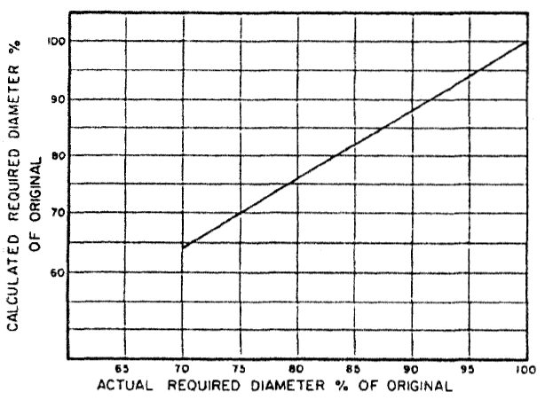 Figure 2 : Impeller Trim Correction
Source : Centrifugal Pump : Design & Application
(Click to view larger chart)
The are two conditions associate to trimming of impeller.
- Specific speed, Ns less than 2500, Impeller trim to be limited to 70%. Trim cut below 70% may cause significant efficiency drop and instable operation.
- Specific speed, NS = 2500-4000, Impeller trim to be limited to 90%. Trim cut
below 90% may cause possible hydraulic problems associated with inadequate vane overlap.
Example,
An existing pump impeller size is 7-in with pump head of 135 ft. What is the impeller trim is required to reduce pump head to 90 ft ?
H2/H1 = (D2/D1)^2
(D2/D1) = (H2/H1)^0.5
(D2/D1) = (90/135)^0.5
(D2/D1) = 0.8163 (81.63%)
From figure 2 : Impeller Trim Correction chart,
Corrected (D2/D1) = 84% (more than 70%, OK for Ns less than 2500)
Thus, D2 = 0.84 x 7 = 5.88 inches.
The associate new Flow (Q) and Power (bhp) can be calculated according to above equation with the D2/D1. The new efficiency can be recalculated base on the Specific Speed (Ns) as discussed in "Estimate Pump Efficiency base on Specific Speed (Ns)".
Above demonstrates the new sets Flow, Power, Head and efficiency for a Trimmed impeller for a single point. If you have the existing pump curve (H vs Q), you may re-establish the new curve (H2 vs Q2) base on existing curve (H1 vs Q1) for a trimmed impeller size (D2). With new curve, you may read the H2 at required pump flow i.e. Qr. If the H2 @ Qr is lower than required pump head (Hr), it signified the impeller is over-trimmed and D2 shall be increased (reduced trim percentage), vice versa until you get the curve with same pump flow (Q1=Q2=Qr) with reduced pump head (H2=Hr).
Related Topic
Related Topic
Labels: Pump
Wednesday, June 18, 2008
Display problem ? Click HERE
 High demand in energy source i.e. petroleum, LNG, etc leads to high pricing of these sources. This has given addition incentive to explore those sour field. Sour field being Oil or gas contains high H2S which potentially lead to material cracking.
What are the problem or concerns related to H2S ?
Toxic
First and far most important concern related to H2S is high toxicity. Human exposure of H2S at high concentration within a short period could lead to fatal.
Environment
H2S release to atmosphere would mix and dissolve in moisture and form acid rain which is corrosive and create human health concerns.
Corrosion & Stress Cracking
i) Sulphide Stress Corrosion Cracking (SSCC)
H2S dissolved in water to form weak acid promote corrosion and form free hydrogen. Free Hydrogen will penetrate the metal, reduce ductility of metal and potentially lead to stress failure below it yield stress, results Sulphide Stress Corrosion Cracking (SSCC).
Sulfide stress corrosion cracking (SSCC) is cracking of metal involving corrosion and tensile stress (residual and/or applied) in the presence of water and H2S. SSC is a form of hydrogen stress cracking (HSC) and involves embrittlement of the metal by atomic hydrogen that is produced by acid corrosion on the metal surface. Hydrogen uptake is promoted in the presence of sulfides. The atomic hydrogen can diffuse into the metal, reduce ductility and increase susceptibility to cracking. High strength metallic materials and hard weld zones are prone to SSC. (Source : NACE MR 0175)
Apart from SSCC, H2S also cause other cracking, including stress corrosion cracking (SCC), hydrogen-induced cracking (HIC) and stepwise cracking (SWC), stress-oriented hydrogen induced cracking (SOHIC), soft zone cracking (SZC) and galvanically induced hydrogen stress cracking.
Hydrogen Stress Cracking (HSC)
HSC refer to cracking that results from the presence of hydrogen in a metal and tensile stress (residual and/or applied). HSC describes cracking in metals that are not sensitive to SSC but which may be embrittled by hydrogen when galvanically coupled, as the cathode, to another metal that is corroding actively as an anode. The term galvanically induced HSC has been used for this mechanism of cracking.*
Stress Corrosion Cracking (SCC)
SCC refer to cracking of metal involving anodic processes of localized corrosion and tensile stress (residual and/or applied) in the presence of water and H2S. Chlorides and/or oxidants and elevated temperature can increase the susceptibility of metals to this mechanism of attacks. *
For Chlorides stress corrosion cracking (CSCC), read more in Chloride Stress Corrosion Cracking & Use correct MOC for seawater service
 Hydrogen-Induced Cracking (HIC)
HIC refer to planar cracking that occurs in carbon and low alloy steels when atomic hydrogen diffuses into the steel and then combines to form molecular hydrogen at trap sites. Cracking results from the pressurization of trap sites by hydrogen. No externally applied stress is needed for the formation of hydrogen-induced cracks. Trap sites capable of causing HIC are commonly found in steels with high impurity levels that have a high density of planar inclusions and/or regions of anomalous microstructure (e.g. banding) produced by segregation of impurity and alloying elements in the steel. This form of hydrogen-induced cracking is not related to welding.*
Stepwise Cracking (SWC)
Hydrogen Stress Cracking (HSC)
HSC refer to cracking that results from the presence of hydrogen in a metal and tensile stress (residual and/or applied). HSC describes cracking in metals that are not sensitive to SSC but which may be embrittled by hydrogen when galvanically coupled, as the cathode, to another metal that is corroding actively as an anode. The term galvanically induced HSC has been used for this mechanism of cracking.*
Stress Corrosion Cracking (SCC)
SCC refer to cracking of metal involving anodic processes of localized corrosion and tensile stress (residual and/or applied) in the presence of water and H2S. Chlorides and/or oxidants and elevated temperature can increase the susceptibility of metals to this mechanism of attacks. *
For Chlorides stress corrosion cracking (CSCC), read more in Chloride Stress Corrosion Cracking & Use correct MOC for seawater service
Hydrogen-Induced Cracking (HIC)HIC refer to planar cracking that occurs in carbon and low alloy steels when atomic hydrogen diffuses into the steel and then combines to form molecular hydrogen at trap sites. Cracking results from the pressurization of trap sites by hydrogen. No externally applied stress is needed for the formation of hydrogen-induced cracks. Trap sites capable of causing HIC are commonly found in steels with high impurity levels that have a high density of planar inclusions and/or regions of anomalous microstructure (e.g. banding) produced by segregation of impurity and alloying elements in the steel. This form of hydrogen-induced cracking is not related to welding.*
Stepwise Cracking (SWC)
SWC refer to cracking that connects hydrogen-induced cracks on adjacent planes in a steel. This term describes the crack appearance. The linking of hydrogen-induced cracks to produce stepwise cracking is dependent upon local strain between the cracks and embrittlement of the surrounding steel by dissolved hydrogen. HIC/SWC is usually associated with low-strength plate steels used in the production of pipes and vessels.*
Stress-Oriented Hydrogen-Induced Cracking (SOHIC)
Stress-Oriented Hydrogen-Induced Cracking (SOHIC)
SOHIC refer to staggered small cracks formed approximately perpendicular to the principal stress (residual or applied) resulting in a “ladderlike” crack array linking (sometimes small) pre-existing HIC cracks. The mode of cracking can be categorized as SSC caused by a combination of external stress and the local strain around hydrogen-induced cracks. SOHIC is related to SSC and HIC/SWC. It has been observed in parent material of longitudinally welded pipe and in the heat-affected zone (HAZ) of welds in pressure vessels. SOHIC is a relatively uncommon phenomenon usually associated with low-strength ferritic pipe and pressure vessel steels.*
Soft Zone Cracking (SZC)
SZC refer to form of SSC that may occur when a steel contains a local “soft zone” of low yield strength material. Under service loads, soft zones may yield and accumulate plastic strain locally, increasing the SSC susceptibility to cracking of an otherwise SSC-resistant material. Such soft zones are typically associated with welds in carbon steels.*
* Source : NACE MR 0175 - ISO 15156
Related Post
- High Temperature Hydrogen Attack in metal & alloy
- Hydrogen Embrittlement TEST method
- Hydrogen present and it's impact to metallurgy
- Different Equation for Pitting Resistance Equivalent Number (PREN)
- Chlorride stress corrosion cracking and use of correct MOC for seawater
- Pitting Corrosion - Mechanism & Prevention
- How a Chloride Stress Corrosion Cracking Lookslike ?
Labels: Chloride Stress Corrosion Cracking, Corrosion Resistance Material, Material
Tuesday, June 17, 2008
Display problem ? Click HERE

A crude transfer pump with capacity of 500 gpm and pump head of 400 ft pumping crude with viscosity of 88 centistokes. With these basic information, Process engineer will prepare a pump specification. Together with other mechanical requirements, all these documents will be submitted to pump vendor for pump quotation. After proper pump selection, pump vendor will submit the quotation with pump curve. The curve indicating performance curve for water instead of crude. The marked operating point on the curve (water) are capacity of 505 gpm, pump head of 417 ft and pump efficiency of 75%. Is the selected pump acceptable ?
Obviously the pump performance curve for water can not be make equivalent to performance when pumping crude with viscosity of 88 centistokes. With following correction charts, the capacity, head and efficiency when pumping crude with identical pump can be found.
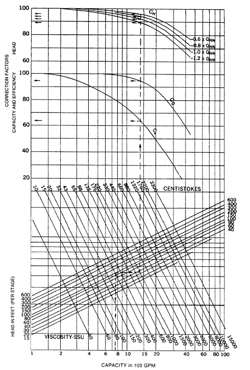 Chart 1 : Correction chart for flow in the range of 100 gpm - 10000 gpm
(Click to view larger chart)
 Chart 1 : Correction chart for flow in the range of 10 gpm - 100 gpm
(Click to view larger chart)
- Capacity correction = 0.99
- Head correction = 0.96
- Efficiency correction = 0.8
The corrected pump capacity when pumping crude @ 88 cSt = 0.99 x 510 gpm = 500 gpm.
The corrected pump head when pumping crude @ 88 cSt = 0.96 x 417 ft = 400 ft.
Above indicated the selected pump is acceptable.
When calculating the pump shaft power, the pump efficiency shall be corrected by multiplying the efficiency obtain from pump curve (water) with efficiency correction.
Related Topic
Labels: Pump
Monday, June 16, 2008
Display problem ? Click HERE
A pump with capacity of 100 m3/h and pump head of 75 m, base on suction drum elevation, fluid condition and suction piping condition, the calculated available Net Positive Suction Head (NPSHa) is 2m. This NPSHa shall be verified with NPSH required (NPSHr) by selected pump.How would you know if NPSHa is sufficient before the pump vendor provide the information on pump required Net Positive Suction Head (NPSHr) ?
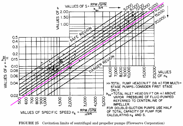
Horizontal axis : Specific speed (Ns)
Vertical axis : Thoma Sigma number, Sigma = NPSHr / H, where H=pump head
Incline line : Suction specific speed (Nss)
All points above the pink line are indicates pump operate in safe region.
From above example, the calculated pump specific speed (Ns) is about 996. From Thoma cavitation curve, with Ns=996 vertically upward cross the pink limiting line, read horizontal to the left, the Thoma sigma number is about 0.04.
Pump required Net Positive Suction Head (NPSHr) is 0.04 x 75 = 3m (more than NPSHa of 2m). This indicated that the pump potential cavitate under normal operation as NPSHa less than NPSHr. Quick action to rectify the drum elevation & pump suction piping design may required to avoid potential future change.
Above pink limiting line was based on suction specific speed, Nss = 11000. In many event, pump manufacturer may design pump with normal Nss of 8000-8500.
Related Topic
- Quick Pump Selection...
- Estimate Pump Efficiency base on Specific Speed (Ns)
- Pump Efficiency Estimation Without Vendor Information
- How to Detect Pump Cativation ?
- How to Increase NPSHa to a Pump ?
- Relationship between NPSHa & NPSHr
- Why Centrifugal pump NPSH required increases with flow ?
Labels: Pump
Sunday, June 15, 2008
Display problem ? Click HERE
Recommended :
 Pressure reduction by self-regulated, pilot operated or full control valve with pressure control loop is common in tank blanketing system. When qualifying control valves for pressure reduction application, there are several factors to consider. This first thing you need to consider is which type of control method you would like to implement in order to have a effective control. Following are some fundamental factors may be consider :
- What is the pressure drop, or the difference between inlet pressure and outlet pressure ?
- What is the set point?
- Will there be large flow variations?
- How critical is the regulation/control?
Droop Effect in a self-regulated valve arrangement is one the important factor to consider. There are several question would be raised when you read about Droop :
- What is the Droop Effect?
- How Droop effect affect control performance ?
- How to reduce Droop effect ?
- How to choose a right valve in this arrangement ?
- What are the general rules ?
Related Topic
Labels: Control valve
Friday, June 13, 2008
Display problem ? Click HERE
Recommended :
 BP went to spud Polaris deep BB II. They spudded on top of an old Telegraph cable that was 3 mile long. They pulled the Drill string BHA last night at 5pm & at 1pm on the 15th May and they are still trying to remove the cable...
If the old Telegraph cable route map information is available, BP may avoid this accident, schedule delay, additional unexpected cost, etc. You can imagine how important is information and information management...


- Pipeline rupture In Varanus Island
- Break the Rules... Pay the Price...
- Vacuum Hazard - Another Catastrophic Factor...
- Dust Explosion Basic & Protection
- Extra Caution When Eliminating Overpressure by Fire Attacks
- Blast rocks Texas oil refinery
Labels: Accident
Thursday, June 12, 2008
Display problem ? Click HERE
Recommended :
 You are assigned to site to make a site visit. Your task is to investigate the serious water hammering issue in the condensate line. In the plant, you found a condensate return line with a pressure gauge indicating 10 barg, you would like to know the temperature of the condensate.
 What is the quickest way to find this temperature with your pocket calculator ?
The simple Square-root-Square-root formula will help you. The formula is :
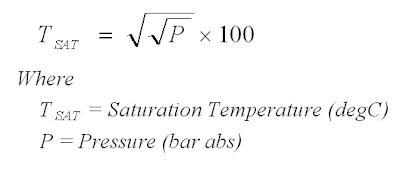
Earlier post "Conduct Steam-Water Balance MANUALLY using Water97_v13" has discussed the saturate steam - condensate temperature can be extracted using a special function, tSat(P) in Excel Add-on in (Water97_v13.xla or Alternative download). Of course, HYSYS has the capability of predicting the saturated steam-condensate temperature. The Saturation temperature at different pressure from 0 to 200 barg have been predicted using HYSYS, Water97_v13.xla and Square-root-Square-root formula. Results tabulated as follow :
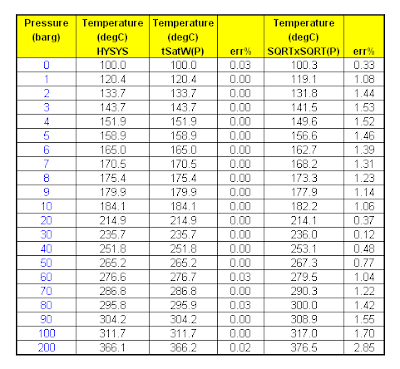
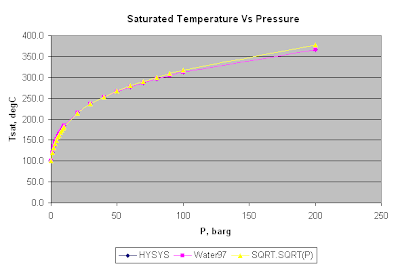
Above simple studies showed that :- tSATW(P) function in Water97_v13.xla is virtually same as HYSYS prediction. Error is negligible.
- Square-root-Square-root formula (compare to HYSYS) constantly over predict saturation temperature over the pressure range from 0-200 barg.
- Square-root-Square-root formula (compare to HYSYS), over-predict is increased with pressure.
- Square-root-Square-root formula (compare to HYSYS) prediction error in the range of 0.3 to less than 3%.
In view of above error, 0.3 to 3% error is rather small and Square-root-Square-root formula can be used to make a quick prediction of saturation temperature for steam-condensate.
Updated on June 15, 2008
- Unit P shall be in bar abs instead of barg. Thanks to Manjushinee.
Related Topic
Updated on June 15, 2008
- Unit P shall be in bar abs instead of barg. Thanks to Manjushinee.
Related Topic
Labels: Rule-Of-Thumb, Steam
