Monday, November 23, 2009
Display problem ? Click HERE
As discussed in "Measures & Technique In Eliminating / Minimizing PWL", one of the measures to reduce Sound Power Level (PWL) at sources PWL is to split the flow. Half the original flow would result approximately 3 dB reduction. This post will discuss how this 3 dB reduction is derived.
A common acceptable method to predict Sound Power Level (PWL in dB) of AIV source is as follow :

A common acceptable method to predict Sound Power Level (PWL in dB) of AIV source is as follow :
Refer to "Sound Power Level (PWL) Prediction from AIV Aspect" for more discussion on above equatio.
Above equation will provide PWLW for a stream with W mass flow. If the stream is split into two stream, the mass flow will be W/2.
Sound Power level for single half-stream (W/2),
PWLW/2 = PWLW + 10Log [(1/2)^2]
PWLW/2 = PWLW - 6
When two half-streams with PWLW/2 are mixed, the resultant PWL of two half-streams may be estimated base on method as discussed in "Calculate Combined Sound Power Level (PWL)".
From this post,
Both half-streams have same PWL. The PWL difference (PWL,diff) is zero (0).
PWL adder = 10 ^ (0.4771 - 0.0795 x PWL,diff)
PWL adder = 10 ^ (0.4771 - 0.0795 x 0)
PWL adder = 3 dB
Both half-streams have same PWL.
Maximum PWL = PWLW/2 = PWLW - 6
Therefore, Combined PWL is :
Combined PWL = PWLW/2 - PWL adder
Combined PWL = PWLW - 6 - 3
Combined PWL = PWLW - 3
So, half the flow will results approximately 3 dB reduction from total flow.
Ref.
i) "Designing Piping Systems Against Acoustically Induced Structural Fatigue", E.L. Eisinger, Journal of Pressure Vessel Technology, Aug 1997.
Related Topic
Above equation will provide PWLW for a stream with W mass flow. If the stream is split into two stream, the mass flow will be W/2.
Sound Power level for single half-stream (W/2),
PWLW/2 = PWLW + 10Log [(1/2)^2]
PWLW/2 = PWLW - 6
When two half-streams with PWLW/2 are mixed, the resultant PWL of two half-streams may be estimated base on method as discussed in "Calculate Combined Sound Power Level (PWL)".
From this post,
Combined PWL = Maximum PWL + PWL Adder
Both half-streams have same PWL. The PWL difference (PWL,diff) is zero (0).
PWL adder = 10 ^ (0.4771 - 0.0795 x PWL,diff)
PWL adder = 10 ^ (0.4771 - 0.0795 x 0)
PWL adder = 3 dB
Both half-streams have same PWL.
Maximum PWL = PWLW/2 = PWLW - 6
Therefore, Combined PWL is :
Combined PWL = PWLW/2 - PWL adder
Combined PWL = PWLW - 6 - 3
Combined PWL = PWLW - 3
So, half the flow will results approximately 3 dB reduction from total flow.
Ref.
i) "Designing Piping Systems Against Acoustically Induced Structural Fatigue", E.L. Eisinger, Journal of Pressure Vessel Technology, Aug 1997.
Related Topic
- Calculate Combined Sound Power Level (PWL)
- Measures & Technique In Eliminating / Minimizing PWL
- Principle in Eliminating & Minimizing AIV Impact
- Energy Input or E-method In Assessing AIV
- Assess AIV with "D/t-method" with Polynomial PWL Limit Line
- Assess AIV with "D/t-method" with Logarithm PWL Limit Line
Wednesday, November 18, 2009
Display problem ? Click HERE

Recommended :
- Tips on Succession in FREE Subscription
- Subscribes to FREE Hydrocarbon Processing

Earlier post "Measures & Technique In Eliminating / Minimizing PWL" discussed about several measures can be considered in eliminating and minimizing PWL for pressure reduction devices. In similar post, Sound Power Level attenuation due to extended "strengthened" pipe has also been presented. This post will focus on approach to estimate combined sound power level (PWL mix) for two or more streams.
In process plant, there will be scenario for two and/or more pressure reduction devices (PRD) downstream piping discharge to a common header. Typical example is blowdown / restriction orifice to flare header. During plant wide total plant blowdown, all blowdown valves may be opened simultaneously or opened in group. Different PRD will results different level of PWL. Now the queries will be :
Mathematically,
PWL Adder
PWL adder is estimated from PWL difference between both stream and the following equations.
If PWL Difference (PWL, diff)
Two Pressure control valves with PWL of 160 dB and 166 dB discharging to a flare header. Calculate combined PWL.
Assumed PWL attenuation due to piping is ignored.
PWL,diff = 166 - 160 = 6 dB
PWL adder = 10 ^ (0.4771 - 0.0795 x 6) = 1 dB
Combined PWL = Maximum PWL + PWL Adder
Combined PWL = 166 + 1 = 167 dB.
Related Topic
- Tips on Succession in FREE Subscription
- Subscribes to FREE Hydrocarbon Processing
Earlier post "Measures & Technique In Eliminating / Minimizing PWL" discussed about several measures can be considered in eliminating and minimizing PWL for pressure reduction devices. In similar post, Sound Power Level attenuation due to extended "strengthened" pipe has also been presented. This post will focus on approach to estimate combined sound power level (PWL mix) for two or more streams.
In process plant, there will be scenario for two and/or more pressure reduction devices (PRD) downstream piping discharge to a common header. Typical example is blowdown / restriction orifice to flare header. During plant wide total plant blowdown, all blowdown valves may be opened simultaneously or opened in group. Different PRD will results different level of PWL. Now the queries will be :
- How these PWL are interact between each and other ?
- How to estimate resultant PWL ?
- Are different PWL addition arithmetically ?
Mathematically,
Combined PWL = Maximum PWL + PWL Adder
PWL Adder
PWL adder is estimated from PWL difference between both stream and the following equations.
If PWL Difference (PWL, diff)
- between 0 to 6 dB, PWL adder = 10 ^ (0.4771 - 0.0795 x PWL,diff)
- between 6 to 10 dB, PWL adder = 10 ^ (0.5651 - 0.0942 x PWL,diff)
- between 10 to 14 dB, PWL adder = 10 ^ (0.5432 - 0.092 x PWL,diff)
- more than 14 dB, PWL adder = 10 ^ (0.7794 - 0.1088 x PWL,diff)
Two Pressure control valves with PWL of 160 dB and 166 dB discharging to a flare header. Calculate combined PWL.
Assumed PWL attenuation due to piping is ignored.
PWL,diff = 166 - 160 = 6 dB
PWL adder = 10 ^ (0.4771 - 0.0795 x 6) = 1 dB
Combined PWL = Maximum PWL + PWL Adder
Combined PWL = 166 + 1 = 167 dB.
Related Topic
- Measures & Technique In Eliminating / Minimizing PWL
- Principle in Eliminating & Minimizing AIV Impact
- Energy Input or E-method In Assessing AIV
- Assess AIV with "D/t-method" with Polynomial PWL Limit Line
- Assess AIV with "D/t-method" with Logarithm PWL Limit Line
- Extra Attention to Common Point and Similarity on AIV Failure
- Piping Excitation When Expose to Acoustic Energy
- Acoustic Induced Vibration (AIV) Fatigue
Tuesday, November 17, 2009
Display problem ? Click HERE

Recommended :
- Tips on Succession in FREE Subscription
- Subscribes to FREE Hydrocarbon Processing
The importance of drop size information has increased considerably during the last decade. Many spray applications such as evaporative cooling, gas conditioning, fire suppression, spray drying and agricultural spraying rely on this information for effective use. It is increasingly important for engineers to understand the basic atomization process and how it is evaluated. Earlier post "Visualize Spraying Nozzle Performance" presented some spray nozzle videos to help in visualizing the performance characteristics of the most common nozzle spray pattern types. In this post, a simple but important booklet may be downloaded to understand further the drop size in spraying technology.
Understand Drop Size- Tips on Succession in FREE Subscription
- Subscribes to FREE Hydrocarbon Processing
The importance of drop size information has increased considerably during the last decade. Many spray applications such as evaporative cooling, gas conditioning, fire suppression, spray drying and agricultural spraying rely on this information for effective use. It is increasingly important for engineers to understand the basic atomization process and how it is evaluated. Earlier post "Visualize Spraying Nozzle Performance" presented some spray nozzle videos to help in visualizing the performance characteristics of the most common nozzle spray pattern types. In this post, a simple but important booklet may be downloaded to understand further the drop size in spraying technology.This booklet is designed to provide engineers with a working knowledge of drop size and related issues. It begins with a brief introduction to atomization and is followed by sections on drop size sampling techniques (methods available for capturing data) and drop size analyzers (methods available for recording data). Sections 4, 5 and 6 discuss the statistics and terminology used in drop size data analysis. Several drop size distribution functions and drop size mean diameter terms are defined and discussed. Factors affecting drop size distribution are discussed in Section 7. Section 8 reviews several forms of drop size data such as graphical and tabular and how data is used. Section 9 addresses practical considerations to take into account when evaluating drop size data. This section examines various aspects of data interpretation to reduce confusion when reviewing reports. Lastly, Section 10 provides a list of reference materials, suggested reading and information on drop size related organizations.
Download
Related Post
- Visualize Spraying Nozzle Performance
- Pump Pressure Versus Head
- Why Centrifugal pump NPSH required increases with flow ?
- Tips for Centrifugal Pump
- Rule-of-thumb For Minimum Flow Recycle
- Basis & Tips on Setting Centrifugal Pump "Warming" Recycle Flow
Friday, November 13, 2009
Display problem ? Click HERE

FREE Chemical Engineering Digital Issue for Nov 2009 already released !
Chemical Engineering Magazine as just released Nov 2009 issue. If you are the subscriber of Chemical Engineering, you should have received similar notification.
A Primer on Spray Drying
Industrial Wireless : Proven Success, Untethered Potential
An explosion of success stories, final ratification of the ISA 100.11a standard and technological improvements have officially removed this technology from the black box of “promised” benefits
Diagnostics: Simplifying Optimization
Improved programming and interfaces are making it easier for end users to marry process control, asset management and diagnostic data
FAYF - Aboveground and Underground Storage Tanks
This one-page guide outlines the pros and cons of using aboveground- and underground-storage tanks
De-emphasize Capital Costs For Pipe Size Selection
Focus more on mass flowrates, fluid densities and operating hours for real savings
Making the Leap from R&D to Manufacturing
Crafting the right information-management strategy is essential to scaling up promising discoveries
Direct-Fired Heaters: Evaluate Thermal Performance and the Effects of Fouling
As process specifications change, heaters often need to accommodate increased capacity. Use these calculations to determine the effects of doing so on fouling
If you are subscriber, you may access previous digital releases. Learn more in "How to Access Previous Chemical Engineering Digital Issue".
If you yet to be subscriber of Chemical Engineering, requested your FREE subscription via this link (click HERE). Prior to fill-up the form, read "Tips on Succession in FREE Subscription".
Related Post
Chemical Engineering Magazine as just released Nov 2009 issue. If you are the subscriber of Chemical Engineering, you should have received similar notification.
***********************
Interesting articles for this month :A Primer on Spray Drying
An understanding of the basic information presented here will help produce powdered products with desired characteristics, while operating the drying plant safely and with minimum energy
Industrial Wireless : Proven Success, Untethered Potential
An explosion of success stories, final ratification of the ISA 100.11a standard and technological improvements have officially removed this technology from the black box of “promised” benefits
Diagnostics: Simplifying Optimization
Improved programming and interfaces are making it easier for end users to marry process control, asset management and diagnostic data
FAYF - Aboveground and Underground Storage Tanks
This one-page guide outlines the pros and cons of using aboveground- and underground-storage tanks
De-emphasize Capital Costs For Pipe Size Selection
Focus more on mass flowrates, fluid densities and operating hours for real savings
Making the Leap from R&D to Manufacturing
Crafting the right information-management strategy is essential to scaling up promising discoveries
Direct-Fired Heaters: Evaluate Thermal Performance and the Effects of Fouling
As process specifications change, heaters often need to accommodate increased capacity. Use these calculations to determine the effects of doing so on fouling
***********************
TIPSIf you are subscriber, you may access previous digital releases. Learn more in "How to Access Previous Chemical Engineering Digital Issue".
If you yet to be subscriber of Chemical Engineering, requested your FREE subscription via this link (click HERE). Prior to fill-up the form, read "Tips on Succession in FREE Subscription".
Related Post
Labels: E-Doc, Education, Learning
Wednesday, November 11, 2009
Recommended :
- Subscribe FREE - Chemical Engineering
- Tips on Succession in FREE Subscription

High frequency acoustic excitation downstream of pressure reducing device potentially results downstream piping failure due to Acoustic Induced Vibration (AIV). Earlier post "Principle in Eliminating & Minimizing AIV Impact" discussed about common principles in minimizing Sound Power level (PWL). This post will discuss in detail the practical measures and techniques in Eliminating and Minimizing PWL.
- Subscribe FREE - Chemical Engineering
- Tips on Succession in FREE Subscription
High frequency acoustic excitation downstream of pressure reducing device potentially results downstream piping failure due to Acoustic Induced Vibration (AIV). Earlier post "Principle in Eliminating & Minimizing AIV Impact" discussed about common principles in minimizing Sound Power level (PWL). This post will discuss in detail the practical measures and techniques in Eliminating and Minimizing PWL.
Type of AIV Source
There are several types of device will generate high frequency vibration. There are :
- Ejector
- Eductor
- Turbo expander
- Pressure relief valve / Rupture disc
- Control valve
- Restriction orifice
Ejector, Eductor & Turbo Expander
Past experiences (published data) have shown that ejector, eductor and turbo expansion is expected to generate high PWL, however there is no published data / information shown failure on AIV. This could be due to it construction which possibly reduce the generation and transmission of vibration level. More studies may be required to understand less AIV threats in these devices.
Past experiences (published data) have shown that ejector, eductor and turbo expansion is expected to generate high PWL, however there is no published data / information shown failure on AIV. This could be due to it construction which possibly reduce the generation and transmission of vibration level. More studies may be required to understand less AIV threats in these devices.
Pressure Relief Devices (PRD)
Pressure relief device (Pressure relief valve / Rupture disc) potentially generate high PWL and lead piping failure due to AIV. However, for old plant design, designer / engineer consider the low operation frequency of this device and may not sufficiently cause piping failure due to AIV. PRD has not been considered as a threat from AIV aspect. Recent experiences have shown the likelihood of PRD downstream piping failure due to AIV is sufficient to results a threat. to the plant and operator . New plant design has started to design system to minimize / avoid the AIV issue downstream of PRD.
Restriction Orifice /Control Valves
Restriction orifice and control valves are devices generate high PWL and past experiences shows piping failure due to AIV.
Measures & Technique In Eliminating / Minimizing PWL
There are several measures can be considered in eliminating and minimizing PWL for pressure reduction devices.
a) Restriction Orifice (RO)
a.i) Multi-staged restriction orifice
Single RO results significant pressure decrease from upstream pressure (Pu) to minimum pressure (Pvc) at vena contrata follow by pressure recovery from minimum pressure (Pvc) to downstream pressure (Pd). The result highly turbulence flow pattern, high cavitation, and non-recoverable energy loses which lead to very high PWL. Provision of multiple RO would reduce above phenomenon and reduce PWL accordingly. For multi-stage RO, it can be implement in at least two ways :
1) Installation Multiple ROs along piping and segregated with piping spool. This is simple but more tedious work.
2) Installation Integrated Multiple ROs. This is even simple, may be high cost and less tedious. Below image is a integrated Multiple RO. Read more in "Multi-Stage Restriction Orifice".

a.ii) Single & Multi-Stage Multi-ported resistance plates
Another way to reduce PWL is use multi-ported RO (single stage and multi-stages) as shown in below image. Read more in "Fisher Baunmann Multi-ported resistance plates". The potential of PWL reduction for multi-ported resistance plates is about 20 dB.


Low noise trim is commonly used in control valve to reduce Sound Power level (PWL) and noise level. There are few design in reducing PWL and there are :
b.i) Staged trim low noise
Staged trim low noise trim is adopted multi-stage pressure letdown similar to multi-stage RO.

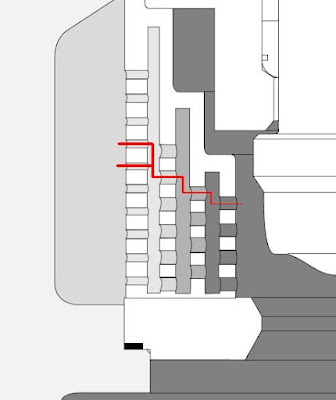
b.ii) Multiple flow path type low noise trim
Multiple flow path low noise trim is one of the very effective noise (Sound Pwer Level) attenuator. It possibly reduce the noise level up to 40 dB. Image below shows a Multiple flow path low noise trim installed in a control valve.


"The "Whisper Trim I" (supplied by Fisher) lowers valve noise by utilizing multiple orifices of special shape, size and spacing. These orifices break up turbulent fluid streams, reducing noise-producing interactions. The trim shifts acoustic energy to higher frequencies that are not readily absorbed by downstream piping. At high frequencies, the piping radiates much less sound in the audible range, which also helps to reduce strain energy and combat piping fatigue. The exit jets from the trim are essentially parallel. This avoids shock cell interaction of the outlet jets that could cause turbulence and noise. Tight shutoff is recommended to protect against high velocity erosion commonly experienced with seat leakage."
Read more in "Fisher® WhisperFlo® Aerodynamic Noise Attenuation Trim".
TIGER TOOTH
TIGER TOOTH design involves concentric grooves (or teeth) machined into the face and backside of a series of circular stacked discs (called a stack), which also acts as a seat retainer. Flow passes from the center of the stack through the teeth undergoing a series of sudden contractions and expansions. Pressure decreases progressively in steps via series of teeths and stacks.

Below is the typical noise reduction / Sound power attenuation curve for TIGER TOOTH low noise trim. Maximum attenuation can be as high as 30 dB.

Read more in "VALTEK TIGER TOOTH"
b.iii) Labyrinth-disk type low noise trim
Another type of low noise trim is the Labyrinth-disk type low noise trim. It works approximate the same way as Multiple flow path type low noise trim.
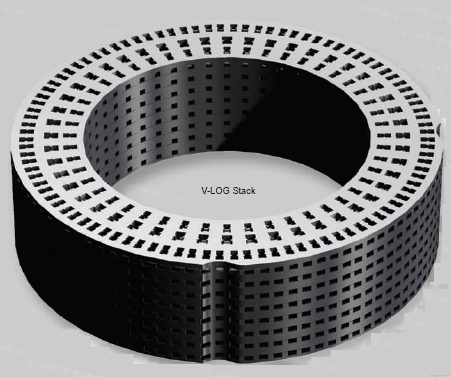
"Noise or Sound Power Level reduction is accomplished by directing the gas through discrete flow channels that are designed with multiple stages consisting of 90 degree turns along with intermediate contractions and expansions in the flow area. The labyrinth flow path of the V-LOG Trim subjects the gas to a high level of friction as it is redirected through each turn in the flow path. V-LOG's patented flow contractions produce maximum flow resistance. In fact, among competing products, Masoneilan's V-LOG Trim yields the highest flow resistance per stage. The enhanced flow geometry of the V-LOG trim creates a series of kinetic energy losses, followed by partial energy recoveries at each stage. This gradual letdown process is highly effective for noise attenuation due to the staged reduction of the fluid pressure."
Read more in "Masoneilan's V-LOG Energy Management Technology" and "72000 Series Large Mass Flow / Low Noise Valve"

Below is the typical noise reduction / Sound power attenuation curve for MEGASTREAM low noise trim. Maximum attenuation can be as high as 28 dB.
Read more in "VALTEK MEGASTREAM".
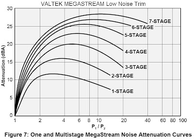
MEGASTREAM
MEGASTREAM trim eliminates the problem of control valve noise by dealing effectively with gaseous pressure reduction, and by controlling turbulence carried into the downstream piping using multi-stage expansion and distribution. Each stage is designed to take a small pressure drop and prevent high velocities present in single-throttling-point trims.


Below is the typical noise reduction / Sound power attenuation curve for MEGASTREAM low noise trim. Maximum attenuation can be as high as 28 dB.

Read more in "VALTEK MEGASTREAM".
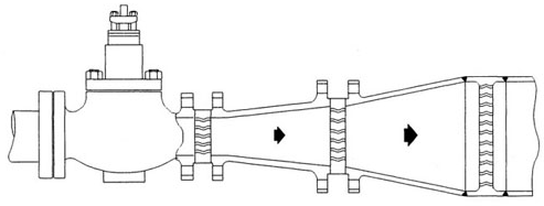
c) Inline Diffuser or Silencer
Inline Diffuser or Silencer is another way to reduce Sound Power level (PWL). A diffuser is a pressure reducing device that is installed downstream from a control valve.

The total pressure drop needed for flow control of a flow control loop is divided between the valve and diffuser. This enables the valve to operate at a lower pressure ratio (Δp/p1) and greatly reduce the control valve noise level. A properly selected diffuser valve combination can result in up to a 40 dBA noise reduction. However, one of the concern is the diffuser internals may subject high level of vibration and possibly failed (past experiences) without knowing. Whenever diffuser or silencer is used for eliminating AIV problem, the reliability of diffuser or silencer shall be taken into account.
d) Split source
This is one of the method in reducing sound power level at source. The principle is to split the AIV source. In general, half the original flow would result approximately 3 dB reduction.
e) Extended "strengthened" pipe
Sound power level (PWL) would reduce along the pipe. Therefore sometimes the "strengthened" (AIV resistance) pipe is extended in order to reduce the sound power level. In general, there will be approximately 3 dB for every 50 pipe nominal diameter.
Related Topic
- Principle in Eliminating & Minimizing AIV Impact
- Energy Input or E-method In Assessing AIV
- Assess AIV with "D/t-method" with Polynomial PWL Limit Line
- Assess AIV with "D/t-method" with Logarithm PWL Limit Line
- Extra Attention to Common Point and Similarity on AIV Failure
- Piping Excitation When Expose to Acoustic Energy
- Acoustic Induced Vibration (AIV) Fatigue
