Sunday, May 2, 2010
High frequency acoustic excitation downstream of pressure reducing device potentially results downstream piping failure due to Acoustic Induced Vibration (AIV). Earlier post "Principle in Eliminating & Minimizing AIV Impact" discussed about common principles in minimizing Sound Power level (PWL). Several proposed measures to reduce Sound Power Level at source discussed in "Measures & Technique In Eliminating / Minimizing PWL".
High Risk Area
Piping downstream of AIV source expose to high Sound Power Level, past experiences shown that high risk location is at circumferential piping with high stress concentration and/or asymmetric piping. Typical example are
- Welded tee or branch in particular large main pipe with small branch,
- Main pipe supported vent / drain
- Main pipe supported instrument connection
- Welded support
- Connection (Tee or elbow) subject to thermal cyclic
- Line / connection subject to sonic flow
Recommendation
The principle is tackling high risk area are minimizing high stress concentration area, reduce asymmetric connection and provide reinforced connection. A few good engineering practices may reduce (but not 100%) risk of AIV problem :
- Avoid using threadolet fittings
AVOID

- Use Sweepolet instead of Weldolet
MAXIMIZE

MINIMIZE

- Use forged type Tee and fittings instead of welded type.
USE

- Use Full Wrap Around reinforcement for welded type tee
USE


- Reinforce welded pipe support
- Use thicker pipe wall (strengthen) of main pipe
Related Topic
- Measures & Technique In Eliminating / Minimizing PWL
- Principle in Eliminating & Minimizing AIV Impact
- Energy Input or E-method In Assessing AIV
- Assess AIV with "D/t-method" with Polynomial PWL Limit Line
- Assess AIV with "D/t-method" with Logarithm PWL Limit Line
- Extra Attention to Common Point and Similarity on AIV Failure
- Piping Excitation When Expose to Acoustic Energy
- Acoustic Induced Vibration (AIV) Fatigue


High frequency acoustic excitation downstream of pressure reducing device potentially results downstream piping failure due to Acoustic Induced Vibration (AIV). Earlier post "Principle in Eliminating & Minimizing AIV Impact" discussed about common principles in minimizing Sound Power level (PWL). Several type of low noise trim in control valve is typical device used to reduce Sound Power Level. There are multi-stage type, multiple path type and Labyrinth-disk type. Details can be read found in "Measures & Technique In Eliminating / Minimizing PWL" and typical low trim trim e.g. WHISPER trim from EMERSON FISHER and V-LOG from DRESSER MASONEILAN are included. This post is to include another two more low noise trim from FLOWSERVE VALTEK.
Two type of low noise trims are provided by FLOWSERVE VALTEK. They are MEGASTREAM and TIGERTOOTH.
MEGASTREAM
MEGASTREAM trim eliminates the problem of control valve noise by dealing effectively with gaseous pressure reduction, and by controlling turbulence carried into the downstream piping using multi-stage expansion and distribution. Each stage is designed to take a small pressure drop and prevent high velocities present in single-throttling-point trims.


Below is the typical noise reduction / Sound power attenuation curve for MEGASTREAM low noise trim. Maximum attenuation can be as high as 28 dB.

Read more in "VALTEK MEGASTREAM".
TIGER TOOTH
TIGER TOOTH design involves concentric grooves (or teeth) machined into the face and backside of a series of circular stacked discs (called a stack), which also acts as a seat retainer. Flow passes from the center of the stack through the teeth undergoing a series of sudden contractions and expansions. Pressure decreases progressively in steps via series of teeths and stacks.

Below is the typical noise reduction / Sound power attenuation curve for TIGER TOOTH low noise trim. Maximum attenuation can be as high as 30 dB.

Read more in "VALTEK TIGER TOOTH"
Related Topic
- Measures & Technique In Eliminating / Minimizing PWL
- Principle in Eliminating & Minimizing AIV Impact
- Energy Input or E-method In Assessing AIV
- Assess AIV with "D/t-method" with Polynomial PWL Limit Line
- Assess AIV with "D/t-method" with Logarithm PWL Limit Line
- Extra Attention to Common Point and Similarity on AIV Failure
- Piping Excitation When Expose to Acoustic Energy
- Acoustic Induced Vibration (AIV) Fatigue
Sunday, April 18, 2010
Earlier post “Process Critical Line” has presented a checklist of process critical line. During design phase, these process shall be checked in detail to minimize or avoid problem such as vibration, hammering, capacity reduction, cavitation, etc to occur. This post will further present good engineering practice for process critical line.
Gravity Flow
Any line subject to gravity flow e.g. drain, flare, vent, etc, low pocket shall be avoided. Liquid or solid accumulate in low pocket potentially result corrosion and blockage. Line should be sloped (and/or free draining) from sources to receiver.
Pump Suction
Line to pump suction should be designed to allow self floating as far as possible where lowest liquid level is above the pump highest point.
Recommended :
- Subscribe FREE - Chemical Engineering
- Tips on Succession in FREE Subscription

Gravity Flow
Any line subject to gravity flow e.g. drain, flare, vent, etc, low pocket shall be avoided. Liquid or solid accumulate in low pocket potentially result corrosion and blockage. Line should be sloped (and/or free draining) from sources to receiver.
Pump Suction
Line to pump suction should be designed to allow self floating as far as possible where lowest liquid level is above the pump highest point.
Recommended :
- Subscribe FREE - Chemical Engineering
- Tips on Succession in FREE Subscription
Ensure minimum submergence of tank to avoid potential vapor being sucked in to pump suction line due to vortex. If positive submergence is not achievable, installation of vortex breaker is another option. Read more in “Vortex Breaker to Avoid Vapor Entrainment”.
Any high pocket shall be avoided and provision of eccentric reducer at the pump suction to avoid potentially vapor lock prior to pump start-up.
Ensure NPSHa is always higher than NPSHr with a positive margin e.g. 1m for entire operation range (turndown to design capacity) and operation conditions (highest operating temperature). There are 17 Ways to Reduce Likelihood of Pump Cavitation.
Minimize suction length and fitting as much as possible to minimize potential of pump cavitation.
Compressor Suction
Compressor suction knock out drum (KOD) may be equipped with mist eliminator e.g. wiremesh to promote droplet coalescing and separation.
KOD vapor exit nozzle should be designed large enough to minimize exit momentum (rho V2 less than 6000 Pa) in order to minimize reentrainment of coalesced liquid droplet into vapor.
Compressor in general can tolerate small amount of liquid. If absolute no liquid is allowed enter compressor as imposed by compressor manufacturer, one may consider provision of insulation to minimize ambient and JT cooling and heat tracing to compensate heat loss due to above mentioned cooling.
Absolute no low pocket shall present in the compressor suction line as low pocket can accumulate liquid and slug of liquid can cause severe damage to compressor.
May consider a compressor suction strainer for start-up and commissioning. As compressor is sensitive to suction line pressure drop, any additional fitting and device at compressor suction can lead to capacity reduction, installation of suction strainer shall be analyzed in detail during design phase.
Flashing / Two phase Gas-Liquid Flow
Slugging and plugging flow in vertical and horizontal potentially results significant vibration to piping. During process design phase, slugging and plugging flow shall be avoided for entire operating range (turndown to design capacity) and operating conditions.
May consider provision of vapor liquid separation and run separator separate header for vapor and liquid line if slugging / plugging flow is unavoidable. For steam header, provide sufficient steam traps to drain-off condensate and minimize potential of slugging flow.
Extra and strengthen support may be provided to avoid severe vibration and failure on pipe crack.
Liquid-Liquid Coalescer
Vapor generation in liquid-liquid coalescer may accumulate and result under-performed liquid-liquid separation. May consider to provide sufficient static head to suppress vapor generation in liquid-liquid coalescer. It is always recommended to provide a vapor equalization line back to separator to release any vapor form in liquid-liquid coalescer.
Low Pressure Line
Minimizing pressure drop in low pressure line is the key factor to ensure proper performance of system. Minimize line length, fittings, elbow, etc and use of smooth surface pipe e.g. stainless steel may be considered.
Potential Surge Line
Steam supply line experience heat loss and condensation due to partially damaged insulation and extreme low ambient temperature. Flashing condensate with steam return to collection header mix with cold condensate. Both condition would results sudden steam collapse and lead to implosion. Steam implosion would generate severe movement of condensate in the collection header and severe vibration of header. Therefore proper maintenance of insulation is extremely important in keep steam line from transient surge. Besides, provide sufficient steam trap to eliminate condensate from steam line.
Long pipeline transferring incompressible fluid e.g. LNG rundown line, produce water injection line, etc potentially experience transient surge (water hammer) in the event of closure of shutdown valve. Transient surge analysis shall be conducted during design phase to ensure surge is avoided. Slower closure of shutdown valve is one of the key component in minimizing surge in long pipe line. Non-slam check valve on the pump discharge may also assist in minimizing surge in long pipeline with pump. Surge suppression system may be considered in the event surge is unavoidable. One shall take note that provision of pressure relief valve may not help to eliminating surge due to slow response time of PRV.
Pressure Relief Valve Inlet & Outlet
May consider discussion and recommendation in :
Any high pocket shall be avoided and provision of eccentric reducer at the pump suction to avoid potentially vapor lock prior to pump start-up.
Ensure NPSHa is always higher than NPSHr with a positive margin e.g. 1m for entire operation range (turndown to design capacity) and operation conditions (highest operating temperature). There are 17 Ways to Reduce Likelihood of Pump Cavitation.
Minimize suction length and fitting as much as possible to minimize potential of pump cavitation.
Compressor Suction
Compressor suction knock out drum (KOD) may be equipped with mist eliminator e.g. wiremesh to promote droplet coalescing and separation.
KOD vapor exit nozzle should be designed large enough to minimize exit momentum (rho V2 less than 6000 Pa) in order to minimize reentrainment of coalesced liquid droplet into vapor.
Compressor in general can tolerate small amount of liquid. If absolute no liquid is allowed enter compressor as imposed by compressor manufacturer, one may consider provision of insulation to minimize ambient and JT cooling and heat tracing to compensate heat loss due to above mentioned cooling.
Absolute no low pocket shall present in the compressor suction line as low pocket can accumulate liquid and slug of liquid can cause severe damage to compressor.
May consider a compressor suction strainer for start-up and commissioning. As compressor is sensitive to suction line pressure drop, any additional fitting and device at compressor suction can lead to capacity reduction, installation of suction strainer shall be analyzed in detail during design phase.
Flashing / Two phase Gas-Liquid Flow
Slugging and plugging flow in vertical and horizontal potentially results significant vibration to piping. During process design phase, slugging and plugging flow shall be avoided for entire operating range (turndown to design capacity) and operating conditions.
May consider provision of vapor liquid separation and run separator separate header for vapor and liquid line if slugging / plugging flow is unavoidable. For steam header, provide sufficient steam traps to drain-off condensate and minimize potential of slugging flow.
Extra and strengthen support may be provided to avoid severe vibration and failure on pipe crack.
Liquid-Liquid Coalescer
Vapor generation in liquid-liquid coalescer may accumulate and result under-performed liquid-liquid separation. May consider to provide sufficient static head to suppress vapor generation in liquid-liquid coalescer. It is always recommended to provide a vapor equalization line back to separator to release any vapor form in liquid-liquid coalescer.
Low Pressure Line
Minimizing pressure drop in low pressure line is the key factor to ensure proper performance of system. Minimize line length, fittings, elbow, etc and use of smooth surface pipe e.g. stainless steel may be considered.
Potential Surge Line
Steam supply line experience heat loss and condensation due to partially damaged insulation and extreme low ambient temperature. Flashing condensate with steam return to collection header mix with cold condensate. Both condition would results sudden steam collapse and lead to implosion. Steam implosion would generate severe movement of condensate in the collection header and severe vibration of header. Therefore proper maintenance of insulation is extremely important in keep steam line from transient surge. Besides, provide sufficient steam trap to eliminate condensate from steam line.
Long pipeline transferring incompressible fluid e.g. LNG rundown line, produce water injection line, etc potentially experience transient surge (water hammer) in the event of closure of shutdown valve. Transient surge analysis shall be conducted during design phase to ensure surge is avoided. Slower closure of shutdown valve is one of the key component in minimizing surge in long pipe line. Non-slam check valve on the pump discharge may also assist in minimizing surge in long pipeline with pump. Surge suppression system may be considered in the event surge is unavoidable. One shall take note that provision of pressure relief valve may not help to eliminating surge due to slow response time of PRV.
Pressure Relief Valve Inlet & Outlet
May consider discussion and recommendation in :
Control Valve & Restriction Orifice
Flow Induced Vibration (FIV) and Acoustic Induced Vibration (AIV) may be studied to identify location of piping which potentially experience high risk of low frequency and high frequency vibration. Minimizing small bore connection may be considered e.g. provision connection with more than 2 inches, avoid using connection smaller than 2 inches. For small bore connection, may consider brazing and extra support to strengthen the connection and avoid pipe cracking.
Anti-cavitation trim could be considered for control valve potentially experience cavitation. Similarly provision of multiple restriction orifice (RO) in series or multi-ported RO may be considered if cavitation occurs in RO.
Related Topic
- Process Critical Line
- Control Valve Cavitation Damage and Solutions
- Problems and Measures for Condensate Recycle Control Valve
- FAQ Related to Control Valves
- Useful Documents Related to Control Valve
- FREE & Reliable Control Valve Sizing Software
- Anti-surge Control (ASC) or Capacity Control (CC) Valve in Vertical Upward Run ?
- Combine Anti-surge control (ASC) & Capacity Control (CC) Functions ?
Labels: AIV, Control valve, Noise, Piping
Tuesday, April 13, 2010
Process design involve line sizing and pressure profile definition. All line size will be presented in Piping & Instrumentation Diagram (P&ID). Nevertheless, there is no line length, elbow and elevation define in P&ID. Upon receipt of P&ID, Piping engineer will begin the piping routing activities and assign necessary length, elbow and elevation to the line. This piping routing may not consistent with assumption taken by process engineer during earlier process design. Significant increase in pressure drop, wrong routing of pipe , incorrect sloping, etc could lead to severe vibration, valve chartering, reduced capacity, under-perform equipment, etc. Therefore it is important for a process engineer to identify Process Critical Line for detail isometric checking. Following will tabulate typical line may experience potential problem and required detail process checking.
Recommended :
- Subscribe FREE - Chemical Engineering
- Tips on Succession in FREE Subscription
Gravity flow
In general most fluid is transferred by pressure from source to destination during normal operation. Pressure head available at source will overcome frictional loss, velocity head and static head. This allow fluid transfer from low point to elevated point. Typical example is transfer liquid from closed drain drum to production separator with the pressure head develop by a reciprocating pump. This kind of pipe is typically know as pressurized pipe. Nevertheless, there are some fluid is transferred by gravity force (or static head). Typical system is closed drain network, process line designed for gravity transfer, etc. Improper design of gravity flow would lead to reduce or no flow.
Pump Suction
Cavitation is phenomenon cause by bubble generation follow by bubble collapsed. More thorough discussion on cavitation phenomenon, cavitation damages and the way to minimize / avoid cavitation can be found in following post :
- What is pump cavitation ?
- How Pump Cavitation Sound and Looks Like ?
- Why Cavitation is Destructive ?
- Damages by Cavitation
- Relationship between NPSHa & NPSHr
Typically to minimize / avoid cavitation damage is to ensure Net Positive Suction Head required (NPSHr) by the pump is lower than the NPSH available (NPSHa) by the system itself. Pump suction line size and routing is a dominant factor affects NPSHa. Improper design of pump suction line would lead to severe cavitation, vibration and pump damage.
Centrifugal Compressor Suction
Centrifugal Compressor capacity is subject to designated flow and compressor inlet condition. Any changes in suction condition (e.g. decrease in density) would seriously affect compressor capacity (e.g. decrease in capacity). Improper design of line between Compressor suction Knock-out drum (KOD) and compressor inlet nozzle would lead to high pressure drop, subsequently lower density and capacity decrease.
Long compressor line (from KOD to compressor) would increase potential of heat loss to ambient (severe during winter time) and results condensation. Present of condensate in vapor to compressor and impinge on compressor impeller when vapor is accelerated potentially damage compressor impeller and severe vibration in compressor.
Flare/Vent Collection Header
Flare / vent collection header has significant impact on built-up backpressure to pressure relief valve. (PRV) Severe pressure drop can lead built-up back pressure exceed it allowable limit e.g. 10% for conventional type PRV. Warm fluid mix with cold fluid in flare header may results two phase gas liquid flow in flare header. Similarly, severe flare header vibration can occur with the present of slugging / plugging flow. Low point in flare line potentially results liquid accumulation in flare line and corrosion may occur. In the major relief event, high velocity vapor pushing accumulated liquid would results slugging flow in the flare line. Liquid column flowing at vapor velocity knocking of elbow/bend may generate severe vibration.
Flashing / Two phase Gas-Liquid Flow
Liquid at saturation point coming from separator potentially flash and two phase gas liquid flow. Typical flow regime is Bubbly flow. Similarly saturated vapor experience ambient cooling and line frictional loss results condensation and two phase gas liquid flow. Typical flow regime is Mist flow. Both Bubbly and Mist flow are not destructive in nature and properly a normal support would be sufficient. Nevertheless, slugging and plugging flow in vertical and horizontal potential results significant vibration to piping. Extra and strengthen support is required to avoid severe vibration and failure on pipe crack. More discussion on Problems Caused by Two Phase Gas-Liquid Flow.
Liquid-Liquid Coalescer
Saturated liquid from separator feeding liquid-liquid separator, any pressure drop increase potentially lead to vapor accumulation and under-performed liquid-liquid separation.Low Pressure Line
Low pressure stream e.g. overhead from amine regeneration column, end flash gas from end flash column, etc is very sensitive to frictional loss.Low pressure here is pressure very close to atmospheric pressure. Any increase in frictional loss will seriously reduce flow through the pipe.
Potential Surge line
Steam supply line experience heat loss and condensation due to partially damaged insulation and extreme low ambient temperature. Flashing condensate with steam return to collection header mix with cold condensate. Both condition would results sudden steam collapse and lead to implosion. Steam implosion would generate severe movement of condensate in the collection header and severe vibration of header. Long pipeline transferring incompressible fluid e.g. LNG rundown line, produce water injection line, etc potentially experience transient surge (water hammer) in the event of closure of shutdown valve. Piping surge is severe in nature and potentially lead to pipe crack and support failure.
Wet Corrosive Service
Some line is normally flow with vapor contains CO2 & H2S and sulfide stress corrosion cracking (SSCC) and general CO2 corrosion is not expected as only vapor flow. During winter low ambient temperature and under turndown operation, ambient cooling potentially lead to vapor condensation and induced SSCC and general corrosion on under-designed piping. Typical example is Condensate stabilizer overhead. Similarly warm wet flare header is normally dry due to continuous dry gas purging. In the event, PRV passing leaks wet vapor into warm wet header or any PRV open follow by closure of PRVs, wet vapor potentially condensed and accumulate in low point and results general corrosion.
Critical Pressure drop line
Line normally design for low pressure drop, any increase in pressure drop could to capacity reduction and/or under-perform downstream unit. Typical example is high pressure gas feeding liquefaction Main Cryogenic Heat Exchanger. Any reduction in Feed pressure to MCHE would lead to higher heat of vaporization and reduce LNG production.
Pressure Relief Valve Inlet
Under normal design condition, PRV inlet line non-recoverable pressure loss shall be limited to 3% of PRV set pressure Any significant increase in line length and elbow (due to piping routing) will results non-recoverable pressure loss increase and lead to PRV chattering.
Pressure Relief Valve Outlet
Upon opening of PRV, instantaneous large gas or vapor passing PRV. High frequency noise is generated results acoustic induced vibration (AIV) which potentially cause discharge pipe cracking. Instantaneous large gas/vapor flow accelerated from zero velocity to maximum velocity will induced high reaction force to downstream piping. Under-designed pipe may crack on high reaction force.
Control valve and Restriction Orifice
Fluid passing control valve and restriction orifice continuously will generate low frequency noise. This noise wave will be transmitted to downstream piping and result Flow Induced Vibration (FIV) which potentially leads to pipe cracking in particular at small bore connection to large line
Saturated liquid passing a control valve or restriction orifice, pressure will began to decrease and lowest pressure closed to vena contracta, follow by pressure recovery once is passed the vena contracta. Lowest pressure point could be lower than vapor pressure of fluid. Vapor bubble will begin to form and once fluid passed through the vena contracta, vapor will start to collapse and results jet wave impacting control valve or restriction or piping. Above phenomenon generally known as cavitation which generate severe vibration to the piping.
Any scenario is normally ignore or miss by engineer where control valve downstream piping may not design for occurrence sonic flow downstream piping. This typically occur in line with control valve discharge to flare/vent header. Sonic flow potentially reduce flowing capacity and how reaction force to piping.
Related Topic
- Control Valve Cavitation Damage and Solutions
- Problems and Measures for Condensate Recycle Control Valve
- FAQ Related to Control Valves
- Useful Documents Related to Control Valve
- FREE & Reliable Control Valve Sizing Software
- Anti-surge Control (ASC) or Capacity Control (CC) Valve in Vertical Upward Run ?
- Combine Anti-surge control (ASC) & Capacity Control (CC) Functions ?
Labels: AIV, Control valve, Noise, Piping
Saturday, January 23, 2010
Recommended :

Cavitation damage and fatigue due to acoustically induced vibration have discussed several times in previous posts such "cavitation" and "AIV". Control valve is known as one the common element / component in a plant potential source of cavitation and AIV related problems. Many efforts in combating both issues were proposed.
Typical solution is anti-cavitation trim e.g. staged trim, multi-flow path trim, labyrinth-disk type trim, etc.
i) Staged trim low noise
Staged trim low noise trim is adopted multi-stage pressure letdown similar to multi-stage RO.

ii) Multiple flow path type low noise trim
Multiple flow path low noise trim is one of the very effective noise (Sound Pwer Level) attenuator. It possibly reduce the noise level up to 40 dB. Image below shows a Multiple flow path low noise trim installed in a control valve.


Read more in "Fisher® WhisperFlo® Aerodynamic Noise Attenuation Trim".
iii) Labyrinth-disk type low noise trim
Another type of low noise trim is the Labyrinth-disk type low noise trim. It works approximate the same way as Multiple flow path type low noise trim.
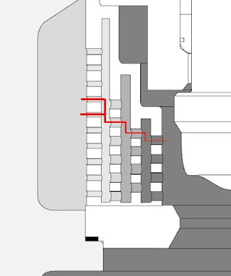
Above trims design is commonly based on general principle in cavitation prevention which is ensure the operating pressure along the flow path in valve trim above fluid vapor pressure. See below image.

Below are some old useful articles related cavitation and multi-stage disc trim available for download. The post part of the continuation post from "Useful Documents Related to Control Valve"
 Fluid kinetic energy as a selection criteria for control valve
A selection criteria is provided that assures a control valve will perform its control function without the attendant problems of erosion, vibration, noise and short life. The criteria involves limits on the fluid kinetic energy exiting through the valve throttling area. Use of this criteria has resolved existing valve problems as demonstrated by retrofitting of the internals of many valves and vibration measurements before and after the retrofit. The selection criteria is to limit the valve throttling exit fluid kinetic energy to 70 psi (480 KPa) or less.
Multi-stage valve trim retrofits vibration eliminate damaging
Through the RHR valve trim retrofit at Quad Cities with multi-stage, tortuous-path, pressure reducing disks and an emergency capacity cage, the damaging vibration previously experience during system test operation has been eliminated. Further, an unlikely repetition of the previously experienced valve blockage by a Rad bag or any other medium has been precluded by the 50% over-capacity cage in the last 20% of valve stroke. Also, previous concerns regarding possible piping fatigue failures within the RHR system as a result of past severe vibration problems have been eliminated.
Specifying control valves for severe-service applications
Large number of the process control valves used in fossil-fired power plants must operate under severe-services conditions—that is, in high-pressure and / or high-temperature applications. When specifying valves for such applications, extreme care must be taken to avoid costly premature failures. This article discusses the stringent requirements that valves must meet to safety operate and deliver long-term performance under severe service conditions. Requirements are examined for both generic and specific applications.
Solving cavitation and Sand Erosion problems
In combating cavitation and erosion, principle in eliminating proposed are multistage velocity control and proper material of construction. Few valve applications in oil and gas production are more destructive and require more continuous maintenance than separator level-control valves. Over the years, the industry has frequently come to accept poor service life in this application. Service lives of a few weeks between complete rebuilds are common. But acceptance of poor service life is no longer necessary.
Control Valve Cavitation
Trim exit velocity is one of the parameter to be considered in control valve selection. Nevertheless, it may not completely explains entire physical phenomena occur in a control valve.The trim velocity approach may not reliable enough in solving problem related to control valve cavitation. The critical pressure drop method and the sigma method which will be introduced proves that the single stage valve may not experience cavitation, despite a trim exit velocity much higher than 100 ft/sec.
Impact of control valve design piping vibration
Vibration of the recycle piping system on the main oil export pumps from a platform in the North Sea raised concern about pipe breakage due to fatigue. Failures had already occurred in associated small bore piping and the instrument air supply lines. and control accessories on the recycle flow control valves. Concern also existed due to the vibration of non-flowing pipe work and systems such as the deck structure, cable trays and other instrumentation, which included fire and gas detection systems. The vibration was finally solved by changing the control valve to a trim that added enough pressure stages to assure the trim exit velocities and energy levels were reduced to levels demonstrated historically as needed in severe service applications. This vibration energy reduction was more than 16 times. This was achieved by reducing the trim exit velocity from peaks of 74 m/s to 12 m/s.
Special thanks to Control Component Inc.
Related Topic
- Problems and Measures for Condensate Recycle Control Valve
- FAQ Related to Control Valves
- Useful Documents Related to Control Valve
- FREE & Reliable Control Valve Sizing Software
- Anti-surge Control (ASC) or Capacity Control (CC) Valve in Vertical Upward Run ?
- Combine Anti-surge control (ASC) & Capacity Control (CC) Functions ?
Labels: AIV, Control valve, Noise
Friday, January 1, 2010
Recommended :
- Subscribe FREE - Chemical Engineering
- Tips on Succession in FREE Subscription
Quick closure of valve will results sudden reversal of forward fluid flow and change in velocity. This action will subsequently results sudden momentum changes and lead to severe vibration and peak force act on the piping. In incompressible (liquid) and multiphase (two phase) fluid, it is similar to an accelerate "liquid column" hammering at a wall. The phenomena is commonly known as "water hammer". Water hammer is unlikely to occur in gas / vapor during quick valve closure due to compressible characteristic.
- Subscribe FREE - Chemical Engineering
- Tips on Succession in FREE Subscription
Quick closure of valve will results sudden reversal of forward fluid flow and change in velocity. This action will subsequently results sudden momentum changes and lead to severe vibration and peak force act on the piping. In incompressible (liquid) and multiphase (two phase) fluid, it is similar to an accelerate "liquid column" hammering at a wall. The phenomena is commonly known as "water hammer". Water hammer is unlikely to occur in gas / vapor during quick valve closure due to compressible characteristic.

Quick closure of valve results sudden change in fluid momentum (+mv to -mv) would lead to instantaneous peak force. Similarly, quick opening of valve for incompressible, multiphase and gas/vapor will results sudden change in momentum (0 to +mv) and subsequently instantaneous peak force acting on the piping. This phenomena is commonly occurs in control valve (CV), Blowdown valve (BDV) and pressure relief device i.e. pressure relief valve (PRV) and rupture disc (RD). The instantaneous peak force acting on the piping may potentially lead to piping failure. An assessment method will be presented below to assess the potential failure of piping due to quick opening of valve.
This post will particularly focus on PRV, RD and BDV with gas/ vapor discharge only.
Peak force induced by sudden gas/vapor release
When a valve quick open from FULL Close to FULL Open, instantaneously release gas/vapor from valve upstream piping to downstream piping at choking velocity results peak force (FMax, kN) as :

W = Vapor mass flow (kg/s)
k = Vapor specific heat ratio
Mw = Vapor molecular weight
T = Temperature (K)
Piping Limiting Force
A steel piping with Piping limiting force (FLimit, kN),

with piping wall thickness correction factor,

Do = Pipe external diameter (m)
Di = Pipe internal diameter (m)
Wt = Pipe wall thickness (mm)
WtSch_40 = Schedule 40 pipe wall thickness (mm)
C = Pipe support correction factor
Pipe support stiffness level and correction factor
Pipe support stiffness level and correction factor subjects to support span length (LS) and pipe external diameter (Do) which can be determined from below chart.

Assessment Criteria
To ensure piping will not failed on sudden opening of valve, the following shall be met :
FMax < 0.3 FLimit
In the event FMax is more than 0.3 but less than 0.5 of FLimit, a detail small bore connection checking shall be conducted.
Ref :
1. "Guideline for avoidance of vibration induced fatigue in process work"
Ref :
1. "Guideline for avoidance of vibration induced fatigue in process work"
Related Post
- Assess Potential Piping Failure Due to Valve Quick Opening with Two-Phase Vapor Liquid
- Quick Determination Pipe Support Stiffness Level and Correction Factor
- Check Valve Types and Selection
- Anti-surge Control (ASC) or Capacity Control (CC) Valve in Vertical Upward Run ?
- Combine Anti-surge control (ASC) & Capacity Control (CC) Functions ?
- Potential Problem associate with Double NRV in Series within a Line
- Several Strategies To Minimize Relief Capacity in Back-Flow Scenario
Monday, December 21, 2009
Display problem ? Click HERE

Recommended :
- Tips on Succession in FREE Subscription
- Subscribes to FREE Hydrocarbon Processing

In process plant, there will be scenario for two and/or more pressure reduction devices (PRD) downstream piping discharge to a common header. Typical example is blowdown / restriction orifice to flare header. During plant wide total plant blowdown, all blowdown valves may be opened simultaneously or opened in group. Different PRD will results different level of PWL.When two Sound power sources are combined, it is understood that the total combined Sound Power Level will increase due to two energy stream are combined. However these energy streams are transmitted in wave form, the resultant Sound Power level will not be added arithmetically i.e. 1+1=2. In earlier post "Calculate Combined Sound Power Level (PWL) Using Graphical Method", an graphical method using PWL adder is presented.
The total combined Sound Power Level is equal to "PWL adder" (which estimated base on PWL difference between both stream and from several experience equations ) plus maximum PWL out of both streams.
Combined PWL = Maximum PWL + PWL Adder
This post will present another analytical method to calculate combined PWL for multiple streams (PWL1, PWL2...)
Total combined Sound Power Level
PWLC = 10 Log10 [+ 10^(PWL1 / 10) + 10^(PWL2 / 10)+...]
Example
Two Pressure control valves with PWL of 160 dB and 166 dB discharging to a flare header. Calculate combined PWL.
Graphical method
Assumed PWL attenuation due to piping is ignored.
PWL,diff = 166 - 160 = 6 dB
PWL adder = 10 ^ (0.4771 - 0.0795 x 6) = 1 dB (refer earlier post).
Combined PWL = Maximum PWL + PWL Adder
Combined PWL = 166 + 1 = 167 dB.
Analytical method
From above analytical equation,
Combined PWL = 10 Log10 [10^(166/10)+10^(160/10)]
Combined PWL = 167 dB
Obviously analytical method is simpler and faster.
Related Topic
- Calculate Combined Sound Power Level (PWL) Using Graphical Method
- Measures & Technique In Eliminating / Minimizing PWL
- Principle in Eliminating & Minimizing AIV Impact
- Energy Input or E-method In Assessing AIV
- Assess AIV with "D/t-method" with Polynomial PWL Limit Line
- Assess AIV with "D/t-method" with Logarithm PWL Limit Line
- Extra Attention to Common Point and Similarity on AIV Failure
Wednesday, December 2, 2009
Display problem ? Click HERE
Rules of thumbs said that every 50D pipe length results approximately 3 dB Sound Power Level (PWL) attenuation where D is in meter (m). This is presented in "Measures & Technique In Eliminating / Minimizing PWL". This post will base on this simple rule-of-thumbs to generate a simple equation for Sound Power Level attenuation due to pipe length.
Derivation
For every pipe length of 50D, the PWL loss will be 3 dB,
PWL loss per meter of pipe length = 3 / 50D = 0.06/D
Sound Power Level attenuation for any pipe length of L,
where
PWLLoss,L = PWL loss per meter pipe length (dB/m)
L = Pipe length (m)
D = Pipe internal diameter (m)
Following is typical graph for Unit PWL versus pipe ID.

Related Topic
Derivation
For every pipe length of 50D, the PWL loss will be 3 dB,
PWL loss per meter of pipe length = 3 / 50D = 0.06/D
Sound Power Level attenuation for any pipe length of L,
PWLLoss,L = 0.06 L/D
where
PWLLoss,L = PWL loss per meter pipe length (dB/m)
L = Pipe length (m)
D = Pipe internal diameter (m)
Following is typical graph for Unit PWL versus pipe ID.

Related Topic
- PWL Reduction By Splitting Flow
- Calculate Combined Sound Power Level (PWL)
- Measures & Technique In Eliminating / Minimizing PWL
- Principle in Eliminating & Minimizing AIV Impact
- Energy Input or E-method In Assessing AIV
- Assess AIV with "D/t-method" with Polynomial PWL Limit Line
- Assess AIV with "D/t-method" with Logarithm PWL Limit Line
Monday, November 23, 2009
Display problem ? Click HERE
As discussed in "Measures & Technique In Eliminating / Minimizing PWL", one of the measures to reduce Sound Power Level (PWL) at sources PWL is to split the flow. Half the original flow would result approximately 3 dB reduction. This post will discuss how this 3 dB reduction is derived.
A common acceptable method to predict Sound Power Level (PWL in dB) of AIV source is as follow :

A common acceptable method to predict Sound Power Level (PWL in dB) of AIV source is as follow :
Refer to "Sound Power Level (PWL) Prediction from AIV Aspect" for more discussion on above equatio.
Above equation will provide PWLW for a stream with W mass flow. If the stream is split into two stream, the mass flow will be W/2.
Sound Power level for single half-stream (W/2),
PWLW/2 = PWLW + 10Log [(1/2)^2]
PWLW/2 = PWLW - 6
When two half-streams with PWLW/2 are mixed, the resultant PWL of two half-streams may be estimated base on method as discussed in "Calculate Combined Sound Power Level (PWL)".
From this post,
Both half-streams have same PWL. The PWL difference (PWL,diff) is zero (0).
PWL adder = 10 ^ (0.4771 - 0.0795 x PWL,diff)
PWL adder = 10 ^ (0.4771 - 0.0795 x 0)
PWL adder = 3 dB
Both half-streams have same PWL.
Maximum PWL = PWLW/2 = PWLW - 6
Therefore, Combined PWL is :
Combined PWL = PWLW/2 - PWL adder
Combined PWL = PWLW - 6 - 3
Combined PWL = PWLW - 3
So, half the flow will results approximately 3 dB reduction from total flow.
Ref.
i) "Designing Piping Systems Against Acoustically Induced Structural Fatigue", E.L. Eisinger, Journal of Pressure Vessel Technology, Aug 1997.
Related Topic
Above equation will provide PWLW for a stream with W mass flow. If the stream is split into two stream, the mass flow will be W/2.
Sound Power level for single half-stream (W/2),
PWLW/2 = PWLW + 10Log [(1/2)^2]
PWLW/2 = PWLW - 6
When two half-streams with PWLW/2 are mixed, the resultant PWL of two half-streams may be estimated base on method as discussed in "Calculate Combined Sound Power Level (PWL)".
From this post,
Combined PWL = Maximum PWL + PWL Adder
Both half-streams have same PWL. The PWL difference (PWL,diff) is zero (0).
PWL adder = 10 ^ (0.4771 - 0.0795 x PWL,diff)
PWL adder = 10 ^ (0.4771 - 0.0795 x 0)
PWL adder = 3 dB
Both half-streams have same PWL.
Maximum PWL = PWLW/2 = PWLW - 6
Therefore, Combined PWL is :
Combined PWL = PWLW/2 - PWL adder
Combined PWL = PWLW - 6 - 3
Combined PWL = PWLW - 3
So, half the flow will results approximately 3 dB reduction from total flow.
Ref.
i) "Designing Piping Systems Against Acoustically Induced Structural Fatigue", E.L. Eisinger, Journal of Pressure Vessel Technology, Aug 1997.
Related Topic
- Calculate Combined Sound Power Level (PWL)
- Measures & Technique In Eliminating / Minimizing PWL
- Principle in Eliminating & Minimizing AIV Impact
- Energy Input or E-method In Assessing AIV
- Assess AIV with "D/t-method" with Polynomial PWL Limit Line
- Assess AIV with "D/t-method" with Logarithm PWL Limit Line
Wednesday, November 18, 2009
Display problem ? Click HERE
Recommended :
- Tips on Succession in FREE Subscription
- Subscribes to FREE Hydrocarbon Processing

Earlier post "Measures & Technique In Eliminating / Minimizing PWL" discussed about several measures can be considered in eliminating and minimizing PWL for pressure reduction devices. In similar post, Sound Power Level attenuation due to extended "strengthened" pipe has also been presented. This post will focus on approach to estimate combined sound power level (PWL mix) for two or more streams.
In process plant, there will be scenario for two and/or more pressure reduction devices (PRD) downstream piping discharge to a common header. Typical example is blowdown / restriction orifice to flare header. During plant wide total plant blowdown, all blowdown valves may be opened simultaneously or opened in group. Different PRD will results different level of PWL. Now the queries will be :
Mathematically,
PWL Adder
PWL adder is estimated from PWL difference between both stream and the following equations.
If PWL Difference (PWL, diff)
Two Pressure control valves with PWL of 160 dB and 166 dB discharging to a flare header. Calculate combined PWL.
Assumed PWL attenuation due to piping is ignored.
PWL,diff = 166 - 160 = 6 dB
PWL adder = 10 ^ (0.4771 - 0.0795 x 6) = 1 dB
Combined PWL = Maximum PWL + PWL Adder
Combined PWL = 166 + 1 = 167 dB.
Related Topic
- Tips on Succession in FREE Subscription
- Subscribes to FREE Hydrocarbon Processing
Earlier post "Measures & Technique In Eliminating / Minimizing PWL" discussed about several measures can be considered in eliminating and minimizing PWL for pressure reduction devices. In similar post, Sound Power Level attenuation due to extended "strengthened" pipe has also been presented. This post will focus on approach to estimate combined sound power level (PWL mix) for two or more streams.
In process plant, there will be scenario for two and/or more pressure reduction devices (PRD) downstream piping discharge to a common header. Typical example is blowdown / restriction orifice to flare header. During plant wide total plant blowdown, all blowdown valves may be opened simultaneously or opened in group. Different PRD will results different level of PWL. Now the queries will be :
- How these PWL are interact between each and other ?
- How to estimate resultant PWL ?
- Are different PWL addition arithmetically ?
Mathematically,
Combined PWL = Maximum PWL + PWL Adder
PWL Adder
PWL adder is estimated from PWL difference between both stream and the following equations.
If PWL Difference (PWL, diff)
- between 0 to 6 dB, PWL adder = 10 ^ (0.4771 - 0.0795 x PWL,diff)
- between 6 to 10 dB, PWL adder = 10 ^ (0.5651 - 0.0942 x PWL,diff)
- between 10 to 14 dB, PWL adder = 10 ^ (0.5432 - 0.092 x PWL,diff)
- more than 14 dB, PWL adder = 10 ^ (0.7794 - 0.1088 x PWL,diff)
Two Pressure control valves with PWL of 160 dB and 166 dB discharging to a flare header. Calculate combined PWL.
Assumed PWL attenuation due to piping is ignored.
PWL,diff = 166 - 160 = 6 dB
PWL adder = 10 ^ (0.4771 - 0.0795 x 6) = 1 dB
Combined PWL = Maximum PWL + PWL Adder
Combined PWL = 166 + 1 = 167 dB.
Related Topic
- Measures & Technique In Eliminating / Minimizing PWL
- Principle in Eliminating & Minimizing AIV Impact
- Energy Input or E-method In Assessing AIV
- Assess AIV with "D/t-method" with Polynomial PWL Limit Line
- Assess AIV with "D/t-method" with Logarithm PWL Limit Line
- Extra Attention to Common Point and Similarity on AIV Failure
- Piping Excitation When Expose to Acoustic Energy
- Acoustic Induced Vibration (AIV) Fatigue
Wednesday, November 11, 2009
Recommended :
- Subscribe FREE - Chemical Engineering
- Tips on Succession in FREE Subscription

High frequency acoustic excitation downstream of pressure reducing device potentially results downstream piping failure due to Acoustic Induced Vibration (AIV). Earlier post "Principle in Eliminating & Minimizing AIV Impact" discussed about common principles in minimizing Sound Power level (PWL). This post will discuss in detail the practical measures and techniques in Eliminating and Minimizing PWL.
- Subscribe FREE - Chemical Engineering
- Tips on Succession in FREE Subscription
High frequency acoustic excitation downstream of pressure reducing device potentially results downstream piping failure due to Acoustic Induced Vibration (AIV). Earlier post "Principle in Eliminating & Minimizing AIV Impact" discussed about common principles in minimizing Sound Power level (PWL). This post will discuss in detail the practical measures and techniques in Eliminating and Minimizing PWL.
Type of AIV Source
There are several types of device will generate high frequency vibration. There are :
- Ejector
- Eductor
- Turbo expander
- Pressure relief valve / Rupture disc
- Control valve
- Restriction orifice
Ejector, Eductor & Turbo Expander
Past experiences (published data) have shown that ejector, eductor and turbo expansion is expected to generate high PWL, however there is no published data / information shown failure on AIV. This could be due to it construction which possibly reduce the generation and transmission of vibration level. More studies may be required to understand less AIV threats in these devices.
Past experiences (published data) have shown that ejector, eductor and turbo expansion is expected to generate high PWL, however there is no published data / information shown failure on AIV. This could be due to it construction which possibly reduce the generation and transmission of vibration level. More studies may be required to understand less AIV threats in these devices.
Pressure Relief Devices (PRD)
Pressure relief device (Pressure relief valve / Rupture disc) potentially generate high PWL and lead piping failure due to AIV. However, for old plant design, designer / engineer consider the low operation frequency of this device and may not sufficiently cause piping failure due to AIV. PRD has not been considered as a threat from AIV aspect. Recent experiences have shown the likelihood of PRD downstream piping failure due to AIV is sufficient to results a threat. to the plant and operator . New plant design has started to design system to minimize / avoid the AIV issue downstream of PRD.
Restriction Orifice /Control Valves
Restriction orifice and control valves are devices generate high PWL and past experiences shows piping failure due to AIV.
Measures & Technique In Eliminating / Minimizing PWL
There are several measures can be considered in eliminating and minimizing PWL for pressure reduction devices.
a) Restriction Orifice (RO)
a.i) Multi-staged restriction orifice
Single RO results significant pressure decrease from upstream pressure (Pu) to minimum pressure (Pvc) at vena contrata follow by pressure recovery from minimum pressure (Pvc) to downstream pressure (Pd). The result highly turbulence flow pattern, high cavitation, and non-recoverable energy loses which lead to very high PWL. Provision of multiple RO would reduce above phenomenon and reduce PWL accordingly. For multi-stage RO, it can be implement in at least two ways :
1) Installation Multiple ROs along piping and segregated with piping spool. This is simple but more tedious work.
2) Installation Integrated Multiple ROs. This is even simple, may be high cost and less tedious. Below image is a integrated Multiple RO. Read more in "Multi-Stage Restriction Orifice".

a.ii) Single & Multi-Stage Multi-ported resistance plates
Another way to reduce PWL is use multi-ported RO (single stage and multi-stages) as shown in below image. Read more in "Fisher Baunmann Multi-ported resistance plates". The potential of PWL reduction for multi-ported resistance plates is about 20 dB.


Low noise trim is commonly used in control valve to reduce Sound Power level (PWL) and noise level. There are few design in reducing PWL and there are :
b.i) Staged trim low noise
Staged trim low noise trim is adopted multi-stage pressure letdown similar to multi-stage RO.
b.ii) Multiple flow path type low noise trim
Multiple flow path low noise trim is one of the very effective noise (Sound Pwer Level) attenuator. It possibly reduce the noise level up to 40 dB. Image below shows a Multiple flow path low noise trim installed in a control valve.
"The "Whisper Trim I" (supplied by Fisher) lowers valve noise by utilizing multiple orifices of special shape, size and spacing. These orifices break up turbulent fluid streams, reducing noise-producing interactions. The trim shifts acoustic energy to higher frequencies that are not readily absorbed by downstream piping. At high frequencies, the piping radiates much less sound in the audible range, which also helps to reduce strain energy and combat piping fatigue. The exit jets from the trim are essentially parallel. This avoids shock cell interaction of the outlet jets that could cause turbulence and noise. Tight shutoff is recommended to protect against high velocity erosion commonly experienced with seat leakage."
Read more in "Fisher® WhisperFlo® Aerodynamic Noise Attenuation Trim".
TIGER TOOTH
TIGER TOOTH design involves concentric grooves (or teeth) machined into the face and backside of a series of circular stacked discs (called a stack), which also acts as a seat retainer. Flow passes from the center of the stack through the teeth undergoing a series of sudden contractions and expansions. Pressure decreases progressively in steps via series of teeths and stacks.Below is the typical noise reduction / Sound power attenuation curve for TIGER TOOTH low noise trim. Maximum attenuation can be as high as 30 dB.
Read more in "VALTEK TIGER TOOTH"
b.iii) Labyrinth-disk type low noise trim
Another type of low noise trim is the Labyrinth-disk type low noise trim. It works approximate the same way as Multiple flow path type low noise trim.
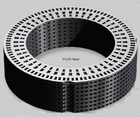
"Noise or Sound Power Level reduction is accomplished by directing the gas through discrete flow channels that are designed with multiple stages consisting of 90 degree turns along with intermediate contractions and expansions in the flow area. The labyrinth flow path of the V-LOG Trim subjects the gas to a high level of friction as it is redirected through each turn in the flow path. V-LOG's patented flow contractions produce maximum flow resistance. In fact, among competing products, Masoneilan's V-LOG Trim yields the highest flow resistance per stage. The enhanced flow geometry of the V-LOG trim creates a series of kinetic energy losses, followed by partial energy recoveries at each stage. This gradual letdown process is highly effective for noise attenuation due to the staged reduction of the fluid pressure."
Read more in "Masoneilan's V-LOG Energy Management Technology" and "72000 Series Large Mass Flow / Low Noise Valve"

Below is the typical noise reduction / Sound power attenuation curve for MEGASTREAM low noise trim. Maximum attenuation can be as high as 28 dB.
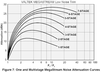
Read more in "VALTEK MEGASTREAM".
MEGASTREAM
MEGASTREAM trim eliminates the problem of control valve noise by dealing effectively with gaseous pressure reduction, and by controlling turbulence carried into the downstream piping using multi-stage expansion and distribution. Each stage is designed to take a small pressure drop and prevent high velocities present in single-throttling-point trims.
Below is the typical noise reduction / Sound power attenuation curve for MEGASTREAM low noise trim. Maximum attenuation can be as high as 28 dB.
Read more in "VALTEK MEGASTREAM".
c) Inline Diffuser or Silencer
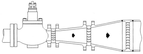
Inline Diffuser or Silencer is another way to reduce Sound Power level (PWL). A diffuser is a pressure reducing device that is installed downstream from a control valve.

The total pressure drop needed for flow control of a flow control loop is divided between the valve and diffuser. This enables the valve to operate at a lower pressure ratio (Δp/p1) and greatly reduce the control valve noise level. A properly selected diffuser valve combination can result in up to a 40 dBA noise reduction. However, one of the concern is the diffuser internals may subject high level of vibration and possibly failed (past experiences) without knowing. Whenever diffuser or silencer is used for eliminating AIV problem, the reliability of diffuser or silencer shall be taken into account.
d) Split source
This is one of the method in reducing sound power level at source. The principle is to split the AIV source. In general, half the original flow would result approximately 3 dB reduction.
e) Extended "strengthened" pipe
Sound power level (PWL) would reduce along the pipe. Therefore sometimes the "strengthened" (AIV resistance) pipe is extended in order to reduce the sound power level. In general, there will be approximately 3 dB for every 50 pipe nominal diameter.
Related Topic
- Principle in Eliminating & Minimizing AIV Impact
- Energy Input or E-method In Assessing AIV
- Assess AIV with "D/t-method" with Polynomial PWL Limit Line
- Assess AIV with "D/t-method" with Logarithm PWL Limit Line
- Extra Attention to Common Point and Similarity on AIV Failure
- Piping Excitation When Expose to Acoustic Energy
- Acoustic Induced Vibration (AIV) Fatigue
