Thursday, October 30, 2008
Display problem ? Click HERE
Recommended :
Subscribe FREE - Chemical Processing
 Multi-stages compressor with intermediate cooling and liquid knock-out is commonly applied in compressing gas from low pressure (say 6 barg) to very high pressure (say 60 barg). This may required 2-stages compression using centrifugal compressor. Intermediate pressure at interstage compressor section could be one-third or half of discharge pressure of final compression stage. Thus in many event, the final stage compression section and intermediate section will have the higher design pressure whilst suction section will have lower design pressure.
Check valve is normally used to install between the two section with different design pressure. Check valve failure (stuck open or leakage) is one of the credible scenario which shall be considered. One of the question is in this check valve failure case, how much back flow shall be considered and how to reduce back-flow and minimize suction Pressure relief valve (PRV) relief capacity ?
Following are some strategies can be considered :
a) Single Check Valve
If single check valve is installed, one shall consider the check valve possibly stuck open. This results 100% back flow through the check valve.
b) Single Check Valve plus Single Shut-down valve
If single check valve and single shutdown valve are installed, one shall consider the check valve possibly stuck open. Although Shutdown valve is available for shut-close purpose, the reliability of single shutdown valve is still insufficient to act as ultimate safeguarding purpose. Thus, this results 100% back flow through the check valve.
c) Double Check Valve
If additional check valve with different technology and manufacturer, one may consider one check valve is stuck open and second check valve is still in place to perform it duty. Nevertheless, one shall not consider the second check valve is 100% reliable and leakage is still possible. Thus, one of the recommendation is to consider 1st check valve full open second check valve leak with 10% check valve flow area.
d) Single Control Valve, Single Check Valve Plus Single Shutdown Valve
If single control valve, single check calve plus single shutdown valve in series are installed and there are at lease two trips are available to trigger back-flow occurrence, this arrangement may be considered acceptable as ultimate safeguard. However, a proper Instrumentation Protective Functional (IPF) studies shall be conducted to confirm.
Import and Debatable Remarks
Fluid Cleanliness Nature - Having say that, above has considered the fluid is clean (no fouling and solid) and will not cause check valve unable to prevent reverse flow. The cleanliness of fluid is one of the critical factor shall be analyzed to derive the safeguarding strategy.
Operation Experiences - Besides cleanliness of fluid, any possible corrosion and surging of system may lead to damage of check valve internal. Some operation experiences shown that there is possibility of check valve internal damaged without operator awareness. Thus, well maintenance procedure and testing and checking procedure is also part of the factors to be considered.
Concluding Remarks
Above strategies may be considered to minimize or eliminate back flow scenario, however a details analysis shall be conducted.
Related Post
Labels: NRV, Overpressure Protection, Pressure Relief Device
Tuesday, October 28, 2008
Display problem ? Click HERE
Recommended :
Subscribes to FREE Hydrocarbon Processing

Carbon Dioxide (CO2) with the present of free water in oil and gas would lead to generation of Carbonic acid. This has been briefly discussed in "CO2 Corrosion in Oil & Gas - Part 1". In this post and "CO2 Corrosion in Oil & Gas - Part 2", there are several articles related to CO2 corrosion.
In earlier discussion in "Quick Estimation of CO2 Corrosion Rate", other than DeWaard and Milliams model, there are other CO2 corrosion models :
Subscribes to FREE Hydrocarbon Processing
Carbon Dioxide (CO2) with the present of free water in oil and gas would lead to generation of Carbonic acid. This has been briefly discussed in "CO2 Corrosion in Oil & Gas - Part 1". In this post and "CO2 Corrosion in Oil & Gas - Part 2", there are several articles related to CO2 corrosion.
In earlier discussion in "Quick Estimation of CO2 Corrosion Rate", other than DeWaard and Milliams model, there are other CO2 corrosion models :
- LIPUCOR model by TOTAL
- HYDROCORR model by SHELL
- CASSANDRA model by BP
- NORSOK M-506 model by NTSI
- KSC model
- IFE model
- etc
M-506 CO2 corrosion rate calculation model
This NORSOK standard, which is a recommended practice, contains
- a computer program for corrosion rate calculations
- a user manual for the computer program. A description of the calculation model, the algorithms and the conditions for the corrosion rate calculations are given. In additions, methods and algorithms for calculation of essential input parameters to the corrosion rate calculations are given.
Download Software
Related Post
- CO2 Corrosion in Oil & Gas - Part 1
- CO2 Corrosion in Oil & Gas - Part 2
- What are the concerns related to H2S ?
- Several Concerns in High CO2 Field Development
- How does Supercritical fluid looks like ?
- High Temperature Hydrogen Attack in metal & alloy
- Hydrogen Embrittlement TEST method
- Chlorride stress corrosion cracking and use of correct MOC for seawater
Sunday, October 26, 2008
Display problem ? Click HERE
Recommended :
Subscribe FREE - Metal Finishing

NACE Standard MR0175 / ISO 15156 - Petroleum and Natural Gas Industries – Materials for use in H2S-containing Environments in Oil and Gas Production was established to provides limits of H2S partial pressure for precautions against sulfide stress cracking (SSC) and guidance for the selection and specification of SSC-resistant materials.
Following are some commonly asked question related to this standard.
Subscribe FREE - Metal Finishing
NACE Standard MR0175 / ISO 15156 - Petroleum and Natural Gas Industries – Materials for use in H2S-containing Environments in Oil and Gas Production was established to provides limits of H2S partial pressure for precautions against sulfide stress cracking (SSC) and guidance for the selection and specification of SSC-resistant materials.
Following are some commonly asked question related to this standard.
- Why NACE MR0175 Called NACE MR0175/ISO 15156 ?
- What is latest error in NACE MR0175 / ISO 15156
- How to use of MR0175 / ISO15156
- How NACE Standards Applied in Farris Pressure Relief Valves ?
- How NACE MR0175-2003 Impact on API 6A Equipemnt and Customer ?
- How ISO 15156 maintenance activities Functions works ?
- How do I know which are the latest editions of the three parts of NACE MR0175/ISO 15156 ?
- Are NACE MR0175/ISO 15156 and ISO 15156 identical in their technical content ?
- Are you aware that the page numbering of NACE and ISO editions of the standard sometimes differ ?
- How do these documents relate to previous editions of NACE MR0175 ?
- How often will the parts of NACE MR0175/ISO 15156 be updated ?
- What happens when amendments are required in the intervening period ?
- What status does a Technical Corrigendum or a Technical Circular have ?
- Are Technical Corrigenda and Technical Circulars incorporated into a standard when it is revised ?
- What is the difference between a Technical Corrigendum and a Technical Circular ?
- Where can Technical Corrigenda and Technical Circulars be obtained ?
- Does the ISO 15156 Maintenance Panel provide a consultancy service concerning materials and their application in sour service ?
- Can the ISO 15156 Maintenance Panel provide advice on the use of alternative materials not listed in the standard ?
- Will the ISO 15156 maintenance Panel provide interpretations for earlier editions of NACE MR0175 ?
- How do I get my material certified to NACE ?
- Is it all right for my company to require compliance with the 2002 version of MR0175 ?
- What do we need to put on the certificate?
- Can you give me the name of someone on a particular committee that I can call to ask a question about a standard ?
- I need to speak with someone who can give me advice on my water treatment system, tell me the best way to apply cathodic protection to my pipeline, or answer another technical question.
- I have a certain opinion on cathodic protection, and my customer has a different opinion. What is NACE’s position on this ?
Related Post
- Material Selection... USER Responsibility
- Error in NACE MR0175 / ISO 15156
- Guideline on Use of MR0175 / ISO15156
- What are the concerns related to H2S ?
- Safety Moment with H2S
- Pyrophoric Fire
- Pitting Corrosion - Mechanism & Prevention
Labels: Corrosion, Material, SSCC
Saturday, October 25, 2008
Display problem ? Click HERE
Recommended :
Subscribe FREE - Metal Finishing
This is a brief history about how NACE MR0175 / ISO 15156 is established since 1950s. It begun after World War II with the establishment of Technical report 1A152 "Sour Oil Well Corrosion" and 1B159 "Well Completion & Corrosion Control of High Pressure Gas Wells" when the demand to gas increased. This followed by NACE 1B163 "Recommendations on Material for Sour Service" and NACE 1F166 "Sulfide Cracking-Resistance Metallic Material for Valves for Production and Pipeline Service" in 1960s. First published of MR 0175 in 1975 and TM0177 "Testing of Metals for Resistance to Sulfide Stress Cracking at Ambient Temperatures" in 1978 and followed by TM0284 "Evaluation of Pipeline Steels for Resistance to Stepwise Cracking" in 1990. MR0175 is then merged with some EFC reports i.e. EFC#16 & #17 and finally first published the NACE MR0175 / ISO 15156 in 2003/2004.
Subscribe FREE - Metal Finishing
This is a brief history about how NACE MR0175 / ISO 15156 is established since 1950s. It begun after World War II with the establishment of Technical report 1A152 "Sour Oil Well Corrosion" and 1B159 "Well Completion & Corrosion Control of High Pressure Gas Wells" when the demand to gas increased. This followed by NACE 1B163 "Recommendations on Material for Sour Service" and NACE 1F166 "Sulfide Cracking-Resistance Metallic Material for Valves for Production and Pipeline Service" in 1960s. First published of MR 0175 in 1975 and TM0177 "Testing of Metals for Resistance to Sulfide Stress Cracking at Ambient Temperatures" in 1978 and followed by TM0284 "Evaluation of Pipeline Steels for Resistance to Stepwise Cracking" in 1990. MR0175 is then merged with some EFC reports i.e. EFC#16 & #17 and finally first published the NACE MR0175 / ISO 15156 in 2003/2004.Critical Improvements
Several critical improvements in the NACE MR 0175 with the published of NACE MR0175 / ISO 15156 in 2003/2004 :
- Inclusion of Stepwise cracking (SWC), Stress Oriented Hydrogen-Induced Cracking (SOHIC), Soft-zone cracking (SZC), etc. Read more on these corrosion type in "What are the concerns related to H2S ?"
- USER who are specifying and/or operating the equipment has full responsibility to ensure a material is works satisfactory in the intended environment. USER is responsible for the material selection. On the other hand, MANUFACTURER is responsible for meeting the metallurgical requirements.
- For revamping/modification of existing facilities and the material was designed for previous revision of NACE MR0175, if USER has the opinion the fluid condition stayed as before, USER may keep the existing material.
- NACE MR0175 / ISO 15156 is solely a guide documents for a proper selection of material in H2S environment. This documents providing list of material resistant to H2S environment, however, the material is not immune to to H2S environment. It implies that improper design, selection, fabrication, etc. may still lead to these material susceptible to H2S environment.
From above statements, the use and implementation of NACE MR0175 / ISO 15156 in H2S environment is within the decision of USER. A metallurgist and material engineer with the assistance of process and chemical engineer within the USER group i.e. COMPANY, CONTRACTOR, and LICENSOR are playing a major role in defining and implementing this standard. DO NOT RELY ON MANUFACTURER & VENDOR !!!
Read more in "Changes to NACE Standard MR0175-2003"
Download
Related Post
Labels: Corrosion, Material, SSCC
Friday, October 24, 2008
Display problem ? Click HERE
Recommended :
Subscribe FREE - Metal Finishing
NACE Standard MR0175 / ISO 15156 - Petroleum and Natural Gas Industries – Materials for use in H2S-containing Environments in Oil and Gas Production was established to provides limits of H2S partial pressure for precautions against sulfide stress cracking (SSC) and guidance for the selection and specification of SSC-resistant materials.
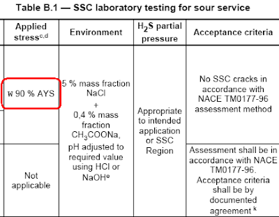
If you refer to NACE MR0175/ISO 15156-2, Table B.1 - SSC laboratory testing for sour service, column 3 "Applied Stress", you will find "w 90 % AYS". See following image.
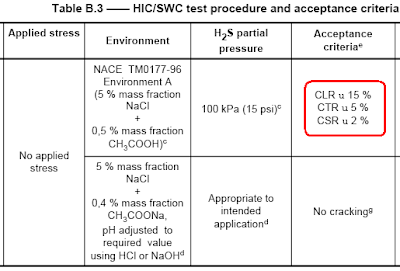
Now, refer to NACE MR0175/ISO 15156-2, Table B.3 - HIC/SWC test procedure and acceptance criteria, column 5 "Acceptance Criteria", you will find "CLR u 15 %", "CTR u 5 %" & "CSR u 2 %". See following image.
What is the meaning of
Download.
Related Post
Subscribe FREE - Metal Finishing
NACE Standard MR0175 / ISO 15156 - Petroleum and Natural Gas Industries – Materials for use in H2S-containing Environments in Oil and Gas Production was established to provides limits of H2S partial pressure for precautions against sulfide stress cracking (SSC) and guidance for the selection and specification of SSC-resistant materials.
If you refer to NACE MR0175/ISO 15156-2, Table B.1 - SSC laboratory testing for sour service, column 3 "Applied Stress", you will find "w 90 % AYS". See following image.
Now, refer to NACE MR0175/ISO 15156-2, Table B.3 - HIC/SWC test procedure and acceptance criteria, column 5 "Acceptance Criteria", you will find "CLR u 15 %", "CTR u 5 %" & "CSR u 2 %". See following image.
What is the meaning of
- "w 90 % AYS"
- "CLR u 15 %"
- "CTR u 5 %"
- "CSR u 2 %"
- "≥ 90 % AYS"
- "CLR ≤ 15 %"
- "CTR ≤ 5 %"
- "CSR ≤ 2 %"
- Table A.3 in NACE MR0175 / ISO 15156-2,
- Table, A.8, A.9, A.17, A.18, A.19...in NACE MR0175 / ISO 15156-3
Download.
Related Post
Tuesday, October 21, 2008
Display problem ? Click HERE
Recommended :
Subscribe FREE - Chemical Processing
Centrifugal compressor is widely used to increase process fluid pressure head to meet process requirement. All centrifugal compressors are equipped with Anti-surge control valve (ASCV) for equipment protective purpose. In many events, This valve may also serve as capacity control valve in order to maintain a specific process parameter.
Subscribe FREE - Chemical Processing
Centrifugal compressor is widely used to increase process fluid pressure head to meet process requirement. All centrifugal compressors are equipped with Anti-surge control valve (ASCV) for equipment protective purpose. In many events, This valve may also serve as capacity control valve in order to maintain a specific process parameter.One of the question being discussed :
Should we locate compressor Anti-surge control (ASC) or Capacity Control (CC) Valve in vertical upward run ?
Should we locate compressor Anti-surge control (ASC) or Capacity Control (CC) Valve in vertical upward run ?
Good engineering practice is to install anti-surge control valve in horizontal run and no low pocket along the inlet and outlet of the control valve to avoid any possible liquid (or solid) accumulation which possibly lead to issues like corrosion, liquid slug, liquid freezing, solid plugging, etc.
Liquid Condensation & Accumulation Causing Corrosion
When ASCV / CCV in close position, vapor with mist liquid may diffuse along the inlet and outlet of ASCV/CCV. Due to heat loss to ambient and/or mist coalescence, mist is possible condensed and accumulated in low pocket and/or downstream of ASCV/CCV downstream on vertical upward run. If the fluid is wet and contains corrosive compounds i.e. Hydrogen Sulfide (H2S), Carbon Dioxide (CO2), low pocket and/or upward run where liquid is accumulated will experience acid corrosion. Pitting and crevice corrosion may be experienced.
Hydrate formation and/or Water Freezing
A fluid with hydrate former and wet, when there is liquid accumulated due to external ambient cooling, there is potential risk of hydrate formation and water freezing. This potential partially or totally clog the recycle line.
Fluid Possibly Crystallization and Solidify
A fluid contain compound possible crystallize and solidify when it is cooled by ambient, when the fluid is cooled by ambient in the stagnant section in recycle line, the fluid is possibly accumulated at low pocket and/or vertical upward run, downstream of ASCV/CCV and crystallized or solidified and plugged the recycle line
Liquid Slugging flow & Induced Vibration
ASCV/CCV is normally closed and liquid is accumulated along the recycle line due to external cooling. In the event of ASCV / CCV open to recycle vapor at compressor discharge back to suction, vapor will push the liquid column flow along the recycle line. This liquid column will be knocking at the ASCV/CCV, bend and tee. Severe slugging and piping vibration may occur and potential damage ASCV/CCV and line.
Thus, it is always recommended to install ASCV / CCV in horizontal run and no low pocket along the inlet and outlet of the control valve that potentially promote corrosion, slugging flow, liquid freezing and solid plugging.
Related Topic
Thus, it is always recommended to install ASCV / CCV in horizontal run and no low pocket along the inlet and outlet of the control valve that potentially promote corrosion, slugging flow, liquid freezing and solid plugging.
Related Topic
- Combine Anti-surge control (ASC) & Capacity Control (CC) Functions ?
- FAQ Related to Control Valves
- Useful Documents Related to Control Valve
- FREE & Reliable Control Valve Sizing Software
- Understand Droop Effect in Self-regulated Control Valve
- WELKER Jet Contorl Valve Handbook
- How to apply valve equation in HYSYS Depressuring ?
Labels: Compressor, Control valve, Surge
Monday, October 20, 2008
Display problem ? Click HERE
Recommended :
Subscribe FREE - Processing Magazine
 H2S dissolved in water to form weak acid promote corrosion and form free hydrogen. Free Hydrogen will penetrate the metal, reduce ductility of metal and potentially lead to stress failure below it yield stress, results Sulphide Stress Corrosion Cracking (SSCC).
Subscribe FREE - Processing Magazine
H2S dissolved in water to form weak acid promote corrosion and form free hydrogen. Free Hydrogen will penetrate the metal, reduce ductility of metal and potentially lead to stress failure below it yield stress, results Sulphide Stress Corrosion Cracking (SSCC).Sulfide stress corrosion cracking (SSCC) is cracking of metal involving corrosion and tensile stress (residual and/or applied) in the presence of water and H2S. SSC is a form of hydrogen stress cracking (HSC) and involves embrittlement of the metal by atomic hydrogen that is produced by acid corrosion on the metal surface. Hydrogen uptake is promoted in the presence of sulfides. The atomic hydrogen can diffuse into the metal, reduce ductility and increase susceptibility to cracking. High strength metallic materials and hard weld zones are prone to SSC.
NACE Standard MR0175 / ISO 15156 - Petroleum and Natural Gas Industries – Materials for use in H2S-containing Environments in Oil and Gas Production was established to provides limits of H2S partial pressure for precautions against sulfide stress cracking (SSC) and guidance for the selection and specification of SSC-resistant materials.
Since the released of this NACE MR0175 / ISO 15156, it has introduced a few more elements into the "sour" service criteria i.e. pH, Chloride contents, etc. This may have created some level of difficulties in understanding and usage of this standard.
Canadian Association of Petroleum Producers (CAPP) has released a document entitle "GUIDE in Use of International Standard NACE MR0175/ISO15156" to provides a supporting document, which may be used as a reference tool to :
- provide a brief overview of the NACE / ISO publication, outlining the most significant changes and their implication to the industry,
- provide guidance and assistance on how to apply the new publication using simple to follow flowcharts, and clarification examples,
- provide sample forms which could be used to meet the intent of the publication.
For those engineer involved in Oil & Gas (upstream) exploration and production, this document is pretty good for understanding and reference.
Download.
Related Post
- What are the concerns related to H2S ?
- Safety Moment with H2S
- Pyrophoric Fire
- Correct model and thermo package in Amine system simulation using HYSYS
- Pitting Corrosion - Mechanism & Prevention
- Hydrogen present and it's impact to metallurgy
- Different Equation for Pitting Resistance Equivalent Number (PREN)
- Chlorride stress corrosion cracking and use of correct MOC for seawater
- How a Chloride Stress Corrosion Cracking Lookslike ?
Labels: Chloride Stress Corrosion Cracking, SSCC
Saturday, October 18, 2008
Display problem ? Click HERE
Recommended :
Subscribes to FREE Hydrocarbon Processing
Control valve is widely used in Oil & gas, refinery, Petrochemical and chemical plant for control purposes of operating parameters i.e temperature, pressure, level, etc. Several articles as compiled in "Useful Documents Related to Control Valve" are pretty useful to many process and chemical engineers.
Centrifugal compressor is widely used to increase process fluid pressure head to meet process requirement. All centrifugal compressors are equipped with Anti-surge control valve (ASCV) for equipment protective purpose. In many events, This valve may also serve as capacity control valve in order to maintain a specific process parameter.
Subscribes to FREE Hydrocarbon Processing
Control valve is widely used in Oil & gas, refinery, Petrochemical and chemical plant for control purposes of operating parameters i.e temperature, pressure, level, etc. Several articles as compiled in "Useful Documents Related to Control Valve" are pretty useful to many process and chemical engineers.Centrifugal compressor is widely used to increase process fluid pressure head to meet process requirement. All centrifugal compressors are equipped with Anti-surge control valve (ASCV) for equipment protective purpose. In many events, This valve may also serve as capacity control valve in order to maintain a specific process parameter.
Anti-surge control valve (ASCV) is one of required equipment protective function for centrifugal compressor. It is used to protect centrifugal compressor from running in surge region, a phenomenon where centrifugal compressor discharge pressure high enough to results reverse flow follow by severe vibration in the compressor chamber. The Anti-surge control valve is recycling discharge gas back to suction to minimize differential pressure across the centrifugal compressor.
Capacity Control valve (CCV) is normally used to maintain a process parameter of a system by recycling excess gas back to compressor suction. Typical process parameters of a system are fix suction pressure, fix discharge pressure and fix differential pressure.
One of the common question raised is :
Should we provide dedicated control valve for anti-surge and capacity control purpose or combine function control valve ?"
 There are several factors lead to separate control valve for dedicate function.
Control Valve Characteristic
This is one of the most important factor to determine if separate control valve is required. For an anti-surge control purpose, the best control valve characteristic is quick opening. However, for capacity control purpose, an equal percentage is mostly used. Thus, this could easy lead to separate control valve with different characteristics used for dedicated function. However, in many occasion, the valve with equal percentage may also serve the purpose of anti-surge control. This is very much subject to compressor characteristic, system operating pressure, system volume, etc. Only way to prove if a single control serve two purpose is Dynamic simulation.
Safety
In many event, the Anti-surge control system together with anti-surge control valve are within a commercial package of compressor. The purpose is to have single point coordination and responsibility and to avoid unnecessary interference. However, using control valve dedicated to Anti-surge control purpose for capacity control purpose would lead to interference and additional signal managing the control valve. Some company safety principle do not allow an protection function used as control function as well. Thus, a separate / dedicate control valve is used. In many recent serious improvement in technology and working method, one control valve serving dual purposes are widely implemented recently.
Wear & Tear
For a control valve serving dual purposes, the control valve may continues in service and this promote wear and tear of the control valve. This would increase the downtime and availability of this control valve. Doubling the control valves will recover the availability again.
Cost
Dedicated control valve for ASCV and CCV is obviously require higher capital investment.
Used of dedicated control valve for anti-surge and capacity control purpose or combine function control valve is subject to case-by-case basis. No one key fit all locks...
Related Topic
- FAQ Related to Control Valves
- Useful Documents Related to Control Valve
- FREE & Reliable Control Valve Sizing Software
- Understand Droop Effect in Self-regulated Control Valve
- WELKER Jet Contorl Valve Handbook
- How to apply valve equation in HYSYS Depressuring ?
- Potential Problem associate with Double NRV in Series within a Line
- 12 Features required for Shutdown Valve (SDV)
Labels: Compressor, Control valve, Surge
Thursday, October 16, 2008
Display problem ? Click HERE
 Simple update to IEM Members or those who are practicing Engineering in MALAYSIA...
The Registration of Engineers Act, 1967 (i.e REA’67 or the Act) has a shelf life of more than 40 years. The Board of Engineers, Malaysia (BEM) was operationalised on the 23rd Aug, 1972 to implement the REA’67. The Act in its original form regulated the natural persons; the Malaysian engineers. Since the BEM came into being, the REA’67 has been amended four (4) times to suit prevailing circumstances, and we now have; registered engineers and ECP’s, Accredited Checkers, etc. Beside the REA’67, we also have the companion “1990 Regulation (2003)”; BEM Guides, and other BEM requirements-all these adding up to what can be described as “Measures” of the Malaysian PRA (i.e. the Professional Regulatory Authority”) over the practice of engineering in the country. Many Malaysian engineers believe that Malaysia needs an act which is suitable for the 21st Century. The IEM being the principle Advocate of the Malaysian Engineering Community, also think so. Accordingly, to get stake-holders’ inputs, a forum on “A New Engineers Act” is hereby proposed.
Date : 23rd October 2008
Time : 9.00 am – 5.00 pm
Venue : PKNS Seminar & Conference Centre
CPD : 8 CPD/PDP hours (BEM Approved)
Panelists : Engr. Rocky HT. Wong, Engr. P.E Chong, Engr. Chen Thiam Leong, Y.Bhg Dato’ Ir. Chew Swee Hock & Ir. Dr. Abdul Majid bin Dato’ Abu Kassim
Registration fee : Member RM 30.00 ; G & S RM 20.00
Wednesday, October 15, 2008
Display problem ? Click HERE
Carbon Dioxide (CO2) with the present of free water in oil and gas would lead to generation of Carbonic acid. This has been briefly discussed in "CO2 Corrosion in Oil & Gas - Part 1". In this post and "CO2 Corrosion in Oil & Gas - Part 2", there are several articles related to CO2 corrosion.
Since the initial studies by DeWaard and Milliams'(1975), there are many other follow-up studies on the CO2 corrosion phenomena. Many CO2 corrosion models have been proposed and used in predicting CO2 corrosion rate. They are :
DeWaard-Milliams nomograph
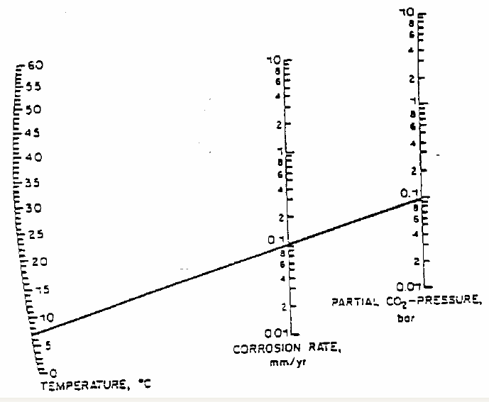
DeWaard and Milliams in their earlier studies has prepared a DeWaard-Milliams nomograph which is pretty simple and useful to have quick estimate for CO2 corrosion rate.
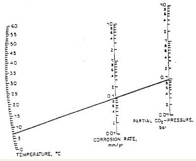
(Click to view larger image)
Since the initial studies by DeWaard and Milliams'(1975), there are many other follow-up studies on the CO2 corrosion phenomena. Many CO2 corrosion models have been proposed and used in predicting CO2 corrosion rate. They are :
- Dewaard- Milliam model
- LIPUCOR model by TOTAL
- HYDROCORR model by SHELL
- CASSANDRA model by BP
- NORSOK M-506 model by NTSI
- KSC model
- IFE model
- etc
DeWaard-Milliams nomograph
DeWaard and Milliams in their earlier studies has prepared a DeWaard-Milliams nomograph which is pretty simple and useful to have quick estimate for CO2 corrosion rate.
(Click to view larger image)
Above is an example where the fluid temperature is about 7 degC with CO2 partial pressure of 0.1 bar, the corrosion rate is 0.1 mm/year.
Related Post
Related Post
- CO2 Corrosion in Oil & Gas - Part 1
- CO2 Corrosion in Oil & Gas - Part 2
- What are the concerns related to H2S ?
- Several Concerns in High CO2 Field Development
- How does Supercritical fluid looks like ?
- High Temperature Hydrogen Attack in metal & alloy
- Hydrogen Embrittlement TEST method
- Chlorride stress corrosion cracking and use of correct MOC for seawater
Monday, October 13, 2008
Display problem ? Click HERE
Earlier post "What are the concerns related to H2S ?" has briefly discussed the concerns of Hydrogen Sulfide (H2S). There are mainly related to toxicity, flammability and corrosivity of H2S. Following are few video clips related to H2S. It provides some in depth understanding of H2S gas.H2S Properties & Characteristic
- H2S is a byproduct formed by decaying of organic matter
- It is toxic, explosive, flammable, corrosive
- Founded in Oil & gas, mining facilities, sewage, wastewater, land filled, etc
- Colorless gas
- Soluble in water
- Smell like rotten egg (sour gas)
- Burn H2S formed SO2, another toxic gas
- Can cause Sulfide Stress Corrosion Cracking (SSCC)
Accidents related to H2S
Truck driver almost killed by H2S
Hydrogen sulfide tanker crashes
Related Post
- What are the concerns related to H2S ?
- High Temperature Hydrogen Attack in metal & alloy
- Hydrogen Embrittlement TEST method
- Hydrogen present and it's impact to metallurgy
- Different Equation for Pitting Resistance Equivalent Number (PREN)
- Chlorride stress corrosion cracking and use of correct MOC for seawater
- Pitting Corrosion - Mechanism & Prevention
- How a Chloride Stress Corrosion Cracking Lookslike ?
Labels: Corrosion
Sunday, October 12, 2008
Display problem ? Click HERE
This is a continuation post from "CO2 Corrosion in Oil & Gas - Part 1" on the useful article related to CO2 corrosion in Oil & Gas.
Recommended :
- Tips on Succession in FREE Subscription
- Subscribe FREE - OilField magazine
 Use of artificial neural networks for predicting crude oil effect on CO2 corrosion of carbon steels
The role of crude oil on CO2 corrosion has gained special attention in the last few years due to its significance when predicting corrosion rates. However, the complexity and variability of crude oils makes it hard to model its effects, which can influence not only wettability properties but also the corrosivity of the associated brine. This study evaluates the usefulness of Artificial Neural Networks (ANN) to predict the corrosion inhibition offered by crude oils as a function of several of their properties which have been related in previous studies to the protectiveness of crude oils, i.e. nitrogen and sulfur contents, resins and asphaltenes, TAN, nickel and vanadium content, etc. Results showed that neural networks are a powerful tool and that the validity of the results is closely linked to the amount of data available and the experience and knowledge that accompany the analysis.
A Stochastic Prediction Model of Localized CO2 Corrosion
In this paper a two-dimensional (2-D) stochastic localized CO2 corrosion model is proposed, which describes the balance of two processes: corrosion (leading to metal loss) and precipitation (leading to metal protection). The model is able to predict localized corrosion of carbon steel in CO2 containing environments. The model uses corrosion rate and surface-scaling tendency predicted by a 1-D mechanistic corrosion model as the inputs. It can predict the possibility of localized corrosion as a function of primitive parameters such as temperature, pH, partial pressure of CO2, velocity, etc. The maximum pit penetration rate as well as the uniform corrosion rate can be predicted and used to describe the severity of the localized attack.
The effect of trace amount of H2S on CO2 corrosion investigated by using the EIS technique
A project has been initiated with the aim of extending the model to cover the effect of H2S on CO2 corrosion. This report covers one of the main building blocks necessary to complete the mechanistic CO2/H2S corrosion model, namely, electrochemistry of API 5L X65 carbon steel CO2 corrosion in the presence of small amounts of H2S (less than 340ppm). The corrosion process monitored by Linear Polarization Resistance (LPR) and Electrochemical Impedance Spectroscopy (EIS) showed a significant decrease in corrosion rate in the presence of H2S due to the metal surface coverage by a sulfide film. This sulfide film was identified as mackinawite by X-ray photoelectron spectroscopy (XPS). Since the experimental results suggested that the mechanism is a retardation of the charge transfer process, the surface coverage was calculated from the corrosion rate. The Langmuir-type adsorption isotherm was successful in modeling the surface coverage by mackinawite in the presence of trace amounts of H2S.
Iron carbonate scale formation and CO2 corrosion in the presence of acetic acid
The role of acetic acid (HAc) on X-65 mild steel carbon dioxide (CO2) corrosion has been investigated in the presence of iron carbonate scale (FeCO3). Free HAc is known to be a source of hydrogen ions and to lead to an increase in mild steel corrosion rates, especially at low pH values. Protective iron carbonate scales form at high temperatures (more than 60°C) and high values of pH. An interesting situation occurs when free HAc and protective FeCO3 scale co-exist. Numerous studies have looked at HAc and FeCO3 scale effects separately, but there is little knowledge of how the protectiveness of FeCO3 scale will be affected, in the presence of acetic acid. Some reports suggested FeCO3 scale thinning and loss of protection in the presence of HAc Thus in order to clarify this aspect of CO2 corrosion, the effect of HAc on FeCO3 scale protectiveness using 3 wt % NaC1 salt solution at T = 80°C has been studied under stagnant conditions. No effect of HAc on FeCO3 scale protectiveness was found over a range of pH and HAc concentrations.
Use and Abuse of EIS in Studying the Mechanisms of CO2/H2S Corrosion of Mild Steel
Electrochemical Impedance Spectroscopy (EIS) is a powerful transient technique which enables an insight into the corrosion process not easily obtained by other predominantly DC techniques. However the EIS technique presents a large challenge both from a theoretical as well as an experimental point of view. Collecting accurate EIS raw data is not easy as EIS is plagues with errors not seen by the DC techniques. Building mechanistic models to capture the EIS data is a very complex task which enables extraction of valuable information about the corrosion process, however the time and effort investment required is very large. In this study of CO2/H2S corrosion of mild steel it was found that a “minor” detail in the experimental set-up caused erroneous acquisition of EIS raw data. These data were “successfully” modeled by using a complex electrochemical theory, which appeared plausible. When the experimental mistake was discovered the EIS data were retaken, the analysis was redone and the conclusions about the corrosion process were completely revised.
Kinetics of Iron Sulfide and Mixed Iron Sulfide/Carbonate Scale Precipitation in CO2/H2S Corrosion
Glass cell experiments were conducted to investigate kinetics of iron sulfide and mixed iron sulfide/carbonate scale precipitation in CO2/H2S corrosion. Weight gain/loss (WGL) method was used to investigate the scale formation using X65 carbon steel as substrates. Scanning Electron Microscopy (SEM/EDS), X-ray Diffraction methodology (XRD), X-ray Photoelectron Spectroscopy (XPS), and Electron Probe Micro-analyzer (EPMA) were used to analyse the scale. The experimental results show that the corrosion products formed in CO2/H2S system depend on the competitiveness of iron carbonate and mackinawite. At high H2S concentration and low Fe2+ concentration, mackinawite was the predominant scale formed on the steel surface. At low H2S concentration and high Fe2+ concentration, both iron carbonate and mackinawite form. It was also found that ferrous ions forming mackinawite scale mainly come from Fe2+ released from the steel surface.
Experimental Study on Water Wetting and CO2 Corrosion in Oil-Water Two-Phase Flow
Internal corrosion occurs only when corrosive water wets the pipe inner wall. However, water wetting is one of most important missing links of our current overall understanding of internal corrosion of oil and gas pipelines. In this study, extensive experimental studies on water wetting in large diameter horizontal oil water pipe flows were carried out. Four main techniques (wall conductance probes, Fe2+ concentration monitoring, wall sampling and flow pattern visualization) were used to determine phase wetting on the internal wall of pipe at different superficial oil and water velocities. Four flow patterns were observed : stratified flow, stratified flow with mixed layer, semi-dispersed and dispersed flows. Three types of phase wetting regimes (water wetting, intermittent wetting and oil wetting) were determined. A comprehensive phase wetting map was obtained based on the overlapping information from these techniques.
Recommended :
- Tips on Succession in FREE Subscription
- Subscribe FREE - Upstream magazine
 CO2 Corrosion of Carbon Steel in High Ionic Strength Brine Solution
Recommended :
- Tips on Succession in FREE Subscription
- Subscribe FREE - Upstream magazine
CO2 Corrosion of Carbon Steel in High Ionic Strength Brine SolutionThe general CO2 corrosion rates of C1018 carbon steel have been measured for NaCl concentrations 3 – 25 wt% at 5ºC, pH4.0. The corrosion process was monitored by linear polarization resistance and potential dynamic sweeps. Experimental results show that high salt concentrations affect the general CO2 corrosion rate significantly and nonlinearly. Potentiodynamicsweep analysis shows that the high content of salt retards both cathodic and anodic process. No significant effects of velocity on corrosion rates are seen for various saline conditions
Basics Revisited - Kinetics of Iron Carbonate Scale Precipitation in CO2 Corrosion
Glass cell experiments were conducted to understand kinetics of iron carbonate scale formation in pure carbon dioxide (CO2) corrosion of mild steel. Weight gain and loss (WGL) method was used as a direct approach to investigate kinetics of scale formation. The experiments were done at the temperatures of 60oC to 90oC, and an iron carbonate supersaturation range of 12 to 350. It is found that the calculated results obtained by the previous kinetics expressions using the traditional dissolved ferrous ion concentration method are one to two orders of magnitude higher than the experimental precipitation rates obtained in the present study by the WGL method. The results show that the main source of the ferrous ions which are involved in formation of the protective iron carbonate scale is the iron dissolution process. It has been clearly demonstrated that the precipitation rate of iron carbonate is directly related to the conditions at the steel surface which can frequently be very different from the one in the bulk fluid.
Case Base Reasoning Model of CO2 Corrosion Based on Field Data
An important aspect in corrosion prediction for oil and gas wells and pipelines is to obtain a realistic estimate of the corrosion rate. Corrosion rate prediction involves developing a predictive model that utilizes commonly available operational parameters, existing lab/field data and theoretical models to obtain realistic assessments of corrosion rates. The Case-based Reasoning (CBR) model for CO2 corrosion prediction is designed to mimic the approach of experienced field corrosion personnel. The model takes knowledge of corrosion rates for existing cases and uses CBR techniques and Taylor series expansion to predict corrosion rates for new fields having somewhat similar parameters. The corrosion prediction using CBR model is developed in three phases: case retrieval, case ranking, and case revision. In case retrieval phase, the database of existing cases is queried in order to identify the group of cases with similar values of critical corrosion parameters. Those cases are ranked in the second phase, using a modified Taylor series expansion of the corrosion function around each case. The most similar case is passed to the third phase: case revision. The correction of the corrosion rate by using a mechanistic corrosion model is utilized in order to predict the corrosion rate of the problem under consideration. The (CBR) model has been implemented as a prototype and verified on a large hypothetical case database and a small field database with real data.
Investigation of the Localized CO2 corrosion Mechanism
Localized CO2 corrosion on mild steel is always associated with the partial breakdown of a protective corrosion product scale such as iron carbonate. The scale breakdown can happen for a variety of reasons many of them related to fluid flow. It is hypothesized that following the scale damage, a galvanic effect is established between the scale covered surface (cathode) and the scale free surface (anode) leading to propagation of localized attack. To test this hypothesis, in a series of laboratory experiments, an iron carbonate scale is formed by a repeatable process. Subsequently, in the so called “scale removal tests” the breakdown of the scale under flowing conditions is investigated. The results show that the iron carbonate scale can be partially removed by mechanical stresses, chemical dissolution or by both mechanisms acting simultaneously. In another series of experiments, a newly developed “artificial pit” test is used to investigate the propagation of localized CO2 corrosion via a galvanic coupling. The artificial pit is composed of a large cathode covered by protective iron carbonate scale, and a small bare steel anode. The two are electrically isolated and connected by a zero resistance ammeter to measure the galvanic current during the tests. The results have confirmed the galvanic mechanism for localized CO2 corrosion propagation. It has been demonstrated that pits will propagate only if the conditions are just right: the solution is neither under-saturated nor heavily supersaturated with respect to iron carbonate, i.e. they are in the so called “grey zone”.
Effect of Organic Acids on CO2 Corrosion
In the majority of the published work related to organic acid corrosion of mild steel, the focus is on acetic acid due to its prevalence in a typical organic acid mix seen in the field. In this work, the electrochemical behaviour of X65 carbon steel in the presence of other important organic acids (formic and propionic) and the effect that these have in the growth and protectiveness of iron carbonate (FeCO3) scale have been investigated. It was found that very little difference exists in electrochemical behaviour of the formic, acetic and propionic acids when it comes to CO2 corrosion of mild steel, given that the pH and concentrations of the undissociated organic acids is the same. Just like the other two weak organic acids, formic acid increases the corrosion rate due to an additional cathodic reaction: direct reduction of undissociated formic acid; this reaction is very temperature sensitive and may be limited by diffusion. The presence of organic acids makes it harder for protective iron carbonate scales to form due to a “scale undermining” effect. The scale precipitation rate is not directly affected, however, the time it takes to reach low corrosion rates is.
To be continue...
Related Post
Related Post
- CO2 Corrosion in Oil & Gas - Part 1
- What are the concerns related to H2S ?
- Several Concerns in High CO2 Field Development
- How does Supercritical fluid looks like ?
- High Temperature Hydrogen Attack in metal & alloy
- Hydrogen Embrittlement TEST method
- Chlorride stress corrosion cracking and use of correct MOC for seawater
Labels: Chloride Stress Corrosion Cracking, CO2, Corrosion
Friday, October 10, 2008
Display problem ? Click HERE

FREE Chemical Engineering Digital Issue for October 2008 has just been released !
Chemical Engineering magazine has just released October 2008 issue. If you are the subscriber of Chemical Engineering, you shall received similar notification.
Interesting articles for this month:
Burning For You
New combustion equipment meets strict NOx regulations while improving operational performance in your plant...
Spotlight on Ammonia and Urea
Huge plants are now the fashion, and the limit has not yet been reached
Using Installed Gain To Improve Valve Selection
Among other things, this analysis is helpful in comparing one valve candidate with another and in exposing over- and under-sized valves...
Valves & Specialty Materials
Advances in material science are minimizing the trade offs we face in material selection for valves...
Report Spray Technology Fundamentals & Applications: Game Winning Strategies
Understanding the fundamentals will help debunk misconceptions and enable better spray applications...
Discharge Coefficients and Flow Resistance Factors
An in depth understanding of the ASME code that describes these terms enables engineers to properly design pressure relief systems...
If you yet to be subscriber of Chemical Engineering, requested your FREE subscription via this link (click HERE). Prior to fill-up the form, read "Tips on Succession in FREE Subscription".
Related Post
- 3 Most Important & FREE Magazines That I Read...
- Non - Technical Quick References for a Chemical & Process Engineers
- R&D engineer, Academician and Student...Don't miss this !
- More You Share More You Learn
- Knowledge is Own by Everyone but Not Someone
- Tips on Succession in FREE Subscription
Labels: E-Doc, Education, Learning
Thursday, October 9, 2008
Display problem ? Click HERE
Recommended :
Subscribe FREE - Utility Automation & Engineering T&D
 Carbon Dioxide (CO2), Hydrogen Sulphide (H2S), Mercury (Hg), Nitrogen (N2), Chloride (Cl) in formation water, etc are components present together in the feedstock for Oil and Gas production, refinery and Liquefied Natural Gas (LNG) production. Presence of CO2 and H2S with free water (H2O) can cause severe corrosion and Sulphide Stress Corrosion Cracking (SSCC) problems in
equipment and piping contact with the oil and gas. Read more in "What are the concerns related to H2S ?". Presence of Hg in Aluminum material i.e. coldbox and MCHE would lead to mercury embrittlement whilst Cl in hot stainless steel surface would lead to Chloride Stress Corrosion Cracking (CSCC). Read more in "Chloride Stress Corrosion Cracking & Use correct MOC for seawater service".
CO2 with presence of free water would lead to generation of Carbonic acid (H2CO3).
When Carbonic Acid contact with steel (Fe), reaction occur.
Useful Article Related to CO2 CorrosionSubscribe FREE - Utility Automation & Engineering T&D
Carbon Dioxide (CO2), Hydrogen Sulphide (H2S), Mercury (Hg), Nitrogen (N2), Chloride (Cl) in formation water, etc are components present together in the feedstock for Oil and Gas production, refinery and Liquefied Natural Gas (LNG) production. Presence of CO2 and H2S with free water (H2O) can cause severe corrosion and Sulphide Stress Corrosion Cracking (SSCC) problems inCO2 with presence of free water would lead to generation of Carbonic acid (H2CO3).
When Carbonic Acid contact with steel (Fe), reaction occur.
2Fe + H2CO3 ==> Fe2CO3 + H2
With minimum level of Oxygen would aggregate the corrosion :
Corrosion without Acid Carbonic :
and Corrosion with Acid Carbonic :
Carbonic acid is weak acid would reduce the pH of fluid and this further aggregate the corrosion.
Corrosion without Acid Carbonic :
and Corrosion with Acid Carbonic :
Carbonic acid is weak acid would reduce the pH of fluid and this further aggregate the corrosion.
Since the initial studies by DeWaard and Milliams'(1975), there are many other follow-up studies on the corrosion phenomena. Videm & Dugstad (1989), Dunlop, Hassell & Rhodes (1983), DeWaard, Lotz & Milliams (1991), But Dugstad (1992), DeWaard & Lotz (1993), Efird, Wright, Boros & Hailey (1993), Dugstad, Lunde & Videm (1994), etc have further studies the CO2 corrosion phenomenon. Following is compilation of articles related to CO2 Corrosion :
Integrated CO2 Corrosion - Multiphase Flow Model
An integrated CO2 corrosion – multiphase flow model was built which takes into account the effect of most important variables. The model is mechanistic in nature and resides on clear theoretical foundations. All the assumptions in the model are explicitly stated and are open to future adjustments and improvements. The overall model was extensively verified with a large experimental database and was able to perform reasonably well in all cases. The multiphase flow model was also benchmarked against a well-established commercial package.
CO2 Corrosion Mechanistic Modeling and Prediction in Horizontal Slug Flow
This paper presents a CO2 corrosion mechanistic model specifically developed for the horizontal multiphase slug flow. It covers electrochemical reactions at the steel surface, transport of reactive species between the metal surface and the bulk, and the chemistry in the bulk solution. The special mass transfer correlations in slug flow were applied in this model. The model can predict the corrosion rate in horizontal slug flow. Comparison with laboratory experimental corrosion results revealed that it could help the understanding of the internal corrosion of horizontal pipeline under slug flow condition. Furthermore, this model shows that the Froude number and the slug frequency are two important factors influencing the internal corrosion rates under multiphase slug flow. This provides an insight for the pipeline design and production under multiphase slug flow.
The Effect of CI- and Acetic Acid on Localized CO2 Corrosion in Wet Gas Flow
Wet gas corrosion rates of C1018 and X65 steel have been measured at the top and bottom of a
high pressure, 10 cm diameter horizontal pipeline under stratified flow conditions with different chloride (Cl-) concentrations. Experiments were performed for 200 hours at 90°C, CO2 partial pressure of 3.8 bar using a superficial gas velocity (Vsg) of 10 m/s and a superficial liquid velocity (Vsl) of 0.1 m/s. Three measurement techniques; ER, LPR, and WL were used simultaneously in the experiments. Localized corrosion occurred at the bottom of the pipe around the iron saturation point. The top of line was well protected by a thin corrosion product film and no localized corrosion was detected. C1018 and X65 have different sensitivities to pitting with a variation in Cl- concentration. Thus the pitting density concept is proposed to describe localized corrosion behavior. Surface analysis on iron carbonate films, by SEM and XRD, revealed different film thicknesses and crystal structures from the top to the bottom of the pipe. Cross-sectional analysis indicates that the thin corrosion product film, usually less than 10 microns, attached to the metal surface, is responsible for the low corrosion rate on top of the line, while the thick and porous film formed on the bottom, generally detached from the metal surface, was responsible for the initiation of localized corrosion.
Subscribes to FREE Hydrocarbon Processing
Top of Line Corrosion in Presence of Acetic Acid and Carbon Dioxide (CO2)
This paper deals with the phenomena of corrosion by acetic acid and carbon dioxide at the top of a horizontal pipeline under dewing conditions. The effect of different parameters known to influence the Top of the Line Corrosion (TLC), such as the condensation rate and the bulk temperature is studied. The free acetic acid concentration varies from 0 to 1000 ppm, the bulk temperature, is set mainly at 70oC, the condensation rate is varied while the partial pressure of carbon dioxide and the gas velocity are set at a fixed value. The presence of acetic acid increases the corrosion rate both at the top and at the bottom of the line in different ways. The condensation rate influences strongly the top of the line corrosion when it has a small influence at the bottom. Evidences of localized corrosion are found at the bottom of the line. The corrosion at the top is uniform in the experiments conducted.
CO2 Corrosion in the Presence of Trace Amounts of H2S
Experiments were conducted to determine the effect of an incremental change in the solution pH, from 4 to 6.6, on CO2 corrosion rates of AISI 1018 steel in the presence of H2S in both single phase flow (Vsl = 1 m/s) and multiphase flow (Vsg=3 m/s, Vsl= 1 m/s) in a large scale multiphase flow loop. Linear polarization probes, electrical resistance probes, and weight loss coupons were used to monitor corrosion rates during 4 to 10 day exposures to a CO2 saturated solution with trace amounts of H2S. The media for experimentation was a 1% NaCl solution at 60ºC, at 7.9 bar (100 psig) total pressure, with gas phase additions of H2S up to 100 ppm. Protective adherent films, seen under these conditions, limited corrosion rates in both single phase and multiphase flow conditions.
Iron carbonate scale growth and the effect of inhibition in CO2 corrosion of mild steel
Investigations were conducted to investigate iron carbonate scale precipitation, the interaction between a corrosion inhibition and the precipitating iron carbonate scale, and their effects on the corrosion rate. Both the effects of iron carbonate precipitation on inhibited and uninhibited surfaces and the effects of inhibition on surfaces with iron carbonate scale were studied. The experiments were done in glass cells at 80 °C and a iron carbonate supersaturation range of 7 – 150. A generic imidazoline based inhibitor was added at various points in the iron carbonate scale formation process. Both corrosion rates and precipitation rates were measured using electrochemical and weight gain/loss methods. The scale was later analyzed using scanning electron microscopy (SEM). It was found that the dissolved ferrous ion concentration method, used previously, overestimates the rate of iron carbonate precipitation. Although no antagonism was found under any of other conditions tested, it was seen that the addition of the inhibitor retarded the growth of the iron carbonate scale.
Effect of acetic acid, pH and MEG on the CO2 top of the line corrosion
This research work presents a study of Top of the Line Corrosion (TLC) on carbon steels in the
presence of carbon dioxide and acetic acid. The influence of different parameters such as the presence of mono-ethylene glycol (MEG) and the use of pH control were studied in a 4” diameter flow loop. Two sets of experiments were conducted; one at 70ºC, high CO2 partial pressure and a “critical” condensation rate and another one at 80ºC, low CO2 partial pressure and a high condensation rate. Weight loss techniques and surface analysis were used to evaluate the corrosion rate and products. It was found that the presence of HAc at the concentrations evaluated does not affect the general corrosion rate at the top of the line. Top of the line corrosion rates correlate with the De Waard / Lotz estimate of 10% of bottom of the line rates15. It is believed that the corrosion mechanism is still controlled by CO2 partial pressure at the experimental conditions evaluated in this study. The presence of MEG has not shown any effect on TLC due to the fact that the condensation rate was kept constant. The use of pH control in the supply is believed to limit the amount of HAc in the condensed water. No clear evidence of localized corrosion or pits can be reported at this stage of the study due to the short time of exposure.
CO2/H2S corrosion under scale forming conditions
Three different mild steel coupons with two different surface areas were exposed to a CO2 saturated multiphase environment with a trace amount of hydrogen sulfide under supersaturated scale forming conditions designed to increase the probability of localized corrosion. Corrosion testing was conducted in the region of low supersaturation values for iron carbonate (SSFeCO3 < 10) and three different supersaturation values for iron sulfide (2.5 < SSFeS < 125) through adjustment of the partial pressure of H2S during 30 day exposures to system conditions. Experiments were conducted in a 1% NaCl solution at 60ºC, pH 6.0, 0.77MPa partial pressure CO2 with trace amounts of H2S in both single phase flow (Vsl = 1 m/s) and multiphase flow (Vsg=3 m/s, Vsl= 1 m/s). Under the conditions tested, both siderite and mackinawite films were developed as adherent corrosion product films. Localized corrosion was observed.
Click CO2 Corrosion in Oil & Gas - Part 2 to continue...
Related Post
Integrated CO2 Corrosion - Multiphase Flow Model
An integrated CO2 corrosion – multiphase flow model was built which takes into account the effect of most important variables. The model is mechanistic in nature and resides on clear theoretical foundations. All the assumptions in the model are explicitly stated and are open to future adjustments and improvements. The overall model was extensively verified with a large experimental database and was able to perform reasonably well in all cases. The multiphase flow model was also benchmarked against a well-established commercial package.
CO2 Corrosion Mechanistic Modeling and Prediction in Horizontal Slug Flow
This paper presents a CO2 corrosion mechanistic model specifically developed for the horizontal multiphase slug flow. It covers electrochemical reactions at the steel surface, transport of reactive species between the metal surface and the bulk, and the chemistry in the bulk solution. The special mass transfer correlations in slug flow were applied in this model. The model can predict the corrosion rate in horizontal slug flow. Comparison with laboratory experimental corrosion results revealed that it could help the understanding of the internal corrosion of horizontal pipeline under slug flow condition. Furthermore, this model shows that the Froude number and the slug frequency are two important factors influencing the internal corrosion rates under multiphase slug flow. This provides an insight for the pipeline design and production under multiphase slug flow.
The Effect of CI- and Acetic Acid on Localized CO2 Corrosion in Wet Gas Flow
Wet gas corrosion rates of C1018 and X65 steel have been measured at the top and bottom of a
high pressure, 10 cm diameter horizontal pipeline under stratified flow conditions with different chloride (Cl-) concentrations. Experiments were performed for 200 hours at 90°C, CO2 partial pressure of 3.8 bar using a superficial gas velocity (Vsg) of 10 m/s and a superficial liquid velocity (Vsl) of 0.1 m/s. Three measurement techniques; ER, LPR, and WL were used simultaneously in the experiments. Localized corrosion occurred at the bottom of the pipe around the iron saturation point. The top of line was well protected by a thin corrosion product film and no localized corrosion was detected. C1018 and X65 have different sensitivities to pitting with a variation in Cl- concentration. Thus the pitting density concept is proposed to describe localized corrosion behavior. Surface analysis on iron carbonate films, by SEM and XRD, revealed different film thicknesses and crystal structures from the top to the bottom of the pipe. Cross-sectional analysis indicates that the thin corrosion product film, usually less than 10 microns, attached to the metal surface, is responsible for the low corrosion rate on top of the line, while the thick and porous film formed on the bottom, generally detached from the metal surface, was responsible for the initiation of localized corrosion.
Subscribes to FREE Hydrocarbon Processing
Top of Line Corrosion in Presence of Acetic Acid and Carbon Dioxide (CO2)This paper deals with the phenomena of corrosion by acetic acid and carbon dioxide at the top of a horizontal pipeline under dewing conditions. The effect of different parameters known to influence the Top of the Line Corrosion (TLC), such as the condensation rate and the bulk temperature is studied. The free acetic acid concentration varies from 0 to 1000 ppm, the bulk temperature, is set mainly at 70oC, the condensation rate is varied while the partial pressure of carbon dioxide and the gas velocity are set at a fixed value. The presence of acetic acid increases the corrosion rate both at the top and at the bottom of the line in different ways. The condensation rate influences strongly the top of the line corrosion when it has a small influence at the bottom. Evidences of localized corrosion are found at the bottom of the line. The corrosion at the top is uniform in the experiments conducted.
CO2 Corrosion in the Presence of Trace Amounts of H2S
Experiments were conducted to determine the effect of an incremental change in the solution pH, from 4 to 6.6, on CO2 corrosion rates of AISI 1018 steel in the presence of H2S in both single phase flow (Vsl = 1 m/s) and multiphase flow (Vsg=3 m/s, Vsl= 1 m/s) in a large scale multiphase flow loop. Linear polarization probes, electrical resistance probes, and weight loss coupons were used to monitor corrosion rates during 4 to 10 day exposures to a CO2 saturated solution with trace amounts of H2S. The media for experimentation was a 1% NaCl solution at 60ºC, at 7.9 bar (100 psig) total pressure, with gas phase additions of H2S up to 100 ppm. Protective adherent films, seen under these conditions, limited corrosion rates in both single phase and multiphase flow conditions.
Iron carbonate scale growth and the effect of inhibition in CO2 corrosion of mild steel
Investigations were conducted to investigate iron carbonate scale precipitation, the interaction between a corrosion inhibition and the precipitating iron carbonate scale, and their effects on the corrosion rate. Both the effects of iron carbonate precipitation on inhibited and uninhibited surfaces and the effects of inhibition on surfaces with iron carbonate scale were studied. The experiments were done in glass cells at 80 °C and a iron carbonate supersaturation range of 7 – 150. A generic imidazoline based inhibitor was added at various points in the iron carbonate scale formation process. Both corrosion rates and precipitation rates were measured using electrochemical and weight gain/loss methods. The scale was later analyzed using scanning electron microscopy (SEM). It was found that the dissolved ferrous ion concentration method, used previously, overestimates the rate of iron carbonate precipitation. Although no antagonism was found under any of other conditions tested, it was seen that the addition of the inhibitor retarded the growth of the iron carbonate scale.
Effect of acetic acid, pH and MEG on the CO2 top of the line corrosion
This research work presents a study of Top of the Line Corrosion (TLC) on carbon steels in the
presence of carbon dioxide and acetic acid. The influence of different parameters such as the presence of mono-ethylene glycol (MEG) and the use of pH control were studied in a 4” diameter flow loop. Two sets of experiments were conducted; one at 70ºC, high CO2 partial pressure and a “critical” condensation rate and another one at 80ºC, low CO2 partial pressure and a high condensation rate. Weight loss techniques and surface analysis were used to evaluate the corrosion rate and products. It was found that the presence of HAc at the concentrations evaluated does not affect the general corrosion rate at the top of the line. Top of the line corrosion rates correlate with the De Waard / Lotz estimate of 10% of bottom of the line rates15. It is believed that the corrosion mechanism is still controlled by CO2 partial pressure at the experimental conditions evaluated in this study. The presence of MEG has not shown any effect on TLC due to the fact that the condensation rate was kept constant. The use of pH control in the supply is believed to limit the amount of HAc in the condensed water. No clear evidence of localized corrosion or pits can be reported at this stage of the study due to the short time of exposure.
CO2/H2S corrosion under scale forming conditions
Three different mild steel coupons with two different surface areas were exposed to a CO2 saturated multiphase environment with a trace amount of hydrogen sulfide under supersaturated scale forming conditions designed to increase the probability of localized corrosion. Corrosion testing was conducted in the region of low supersaturation values for iron carbonate (SSFeCO3 < 10) and three different supersaturation values for iron sulfide (2.5 < SSFeS < 125) through adjustment of the partial pressure of H2S during 30 day exposures to system conditions. Experiments were conducted in a 1% NaCl solution at 60ºC, pH 6.0, 0.77MPa partial pressure CO2 with trace amounts of H2S in both single phase flow (Vsl = 1 m/s) and multiphase flow (Vsg=3 m/s, Vsl= 1 m/s). Under the conditions tested, both siderite and mackinawite films were developed as adherent corrosion product films. Localized corrosion was observed.
Click CO2 Corrosion in Oil & Gas - Part 2 to continue...
Related Post
- What are the concerns related to H2S ?
- Several Concerns in High CO2 Field Development
- How does Supercritical fluid looks like ?
- High Temperature Hydrogen Attack in metal & alloy
- Hydrogen Embrittlement TEST method
- Chlorride stress corrosion cracking and use of correct MOC for seawater
- Pitting Corrosion - Mechanism & Prevention
- How a Chloride Stress Corrosion Cracking Lookslike ?
Labels: Chloride Stress Corrosion Cracking, CO2, Corrosion
