Thursday, January 31, 2008
 Membrane has been utilised in removal of CO2 in raw gas in offshore platform. Preliminary simulation of CO2 removal by membrane can be done with just a simple COMPONENT SPLITTER in HYSYS until licensor feed contractor with correct and mature information.
Let take an example. wet gas with (C1, C2, C3, N2, Helium & CO2) contain 20 mole% CO2 and would like to bring down to 5 mole% in product. You may simulate wet gas feeding the COMPONENT SPLITTER and use an ADJUST to adjust the CO2 split so that the CO2 in product is 5 mole%. Following image shown a typical scheme.


Certainly the wet gas composition is subject to change and additional component (i-C4 & n-C4) needs to be included in the wet gas composition. This is rather simple step where you may goes in to the SIMULATION ENVIRONMENT to add these two components. See following image.

Once you have done and back to main simulator, you may / may not notice there are some changes to the simulation. See following image. When you just return from SIMULATION ENVIRONMENT, the ADJ-1 (ADJUST) is in WARNING mode (Y ellow line) but simulator allow continue progress.

Click on ADJUST, you may find that the adjust and target parameters have changed. See following images.

Simple process simulation as per above, you may be able to trace the error. However, you may not seen this error for large process plant like NGL extraction, LNG production, refinery, etc. This error exist in HYSYS version 2006 as well other version. Removal of component will have similar issue.
TIPS
It is always advised :
- Firm up component as early as you can
- Do NOT removal component if not neccessary. Let it stay in the simulation and set fraction to zero.
- If you can not avoid adding new component, analyse the impact, identify which unit operation will be affected, and plan properly what you need to watch-out after you have added the component.
- Before proceed, SAVE your file as backup.
- Whenever you have added component and return from SIMULATION ENVIRONMENT, put system in HOLD mode. Adjust the parameter before you let the simulation resume. Otherwise your simulation will not converge.
- Always check unit operation involve component adjustment after you have added new component
Still have not aware any solution or workaround yet. Do you aware of any ?
Related Topic
- What to do if HYSYS 3.2 Can not Locate License Server ?
- Lesson Leaned from Installation of SHELL FRED
- Bug in ASPENTECH HYSYS 2006 Dynamic Depressuring Fisher Valve model
- How to apply valve equation in HYSYS Depressuring ?
- Simulate Trayed & Packed bed column in HYSYS
- Correct model and thermo package in Amine system simulation using HYSYS
- How to differentiate MASS lower heating value and Volumetric Lower heating value (gas) in HYSYS ?
Labels: HYSYS
Wednesday, January 30, 2008
I have noticed there are many engineers still asking a simple question. In determining if a Pressure Relief Device is required for tube rupture, should we apply two-third (2/3) rule or ten-thirteen (10/13) rule ?

For those who has read my earlier post “Criteria for Requirement of Pressure Relief Device for Tube Rupture” may have aware that two-third (2/3) rule or ten-thirteen (10/13) rule are basically derivation of above criteria. Both are correct BUT subject to design code and revision of vessel being designed to.
WHY two-third (2/3) rule ?
Earlier revision of ASME required that equipment and piping be tested at 150% of stated design pressure. If the equipment design pressure is 15 barg, then the test pressure must be 22.5 barg, thus 15/22.5 = 2/3. API RP 521 (1997 edition) stated that if the design pressure of the low-pressure side (LPS) is at least 2/3 of the design pressure of the high pressure side (HPS), tube rupture is not considered a credible relieving scenario.
WHY ten-thirteen (10/13) rule?
In latest ASME, it stated that the test pressure of equipment to be 130% of the design pressure. If the equipment design pressure is 15 barg, then the test pressure shall be 19.5 barg, thus 15/19.5 = 10/13. Similarly follow API RP 521 (1997 edition) statement, if the design pressure of the low-pressure side (LPS) is at least 10/13 of the design pressure of the high pressure side (HPS), tube rupture is not considered a credible relieving scenario.
In latest API STD 521, a more reasonable statement is the corrected test pressure of low pressure side (LPS) is more than the design pressure of high pressure side (HPS), tube rupture may not be considered a credible relieving scenario. This statement is applicable to any test pressure requirement.
In latest API STD 521, a more reasonable statement is the corrected test pressure of low pressure side (LPS) is more than the design pressure of high pressure side (HPS), tube rupture may not be considered a credible relieving scenario. This statement is applicable to any test pressure requirement.
WHY both are correct ?
One shall remember, the equipment may be designed to latest ASME code which called for test pressure to be 130% of equipment design pressure. Then ten-thirteen (10/13) rule is applied. But if the vessel is designed to AS (Australia), GB (China), etc which both standards still call for equipment test pressure to be 150% of equipment design pressure with stress correction, then two-third (2/3) rule still applied. Thus, whenever consider a tube rupture scenario, the design code of the vessel shall always be taken into consideration. Nevertheless, latest API STD 521 statement still applicable in conjunction with equipment design to any code (ASME, AS, GB, JIS, etc).
Updated :
June 07, 2008 : "...within" changed to "...at least". Thanks to swakee.
Sept 20, 2008 : "22.5/15" to "15/22.5"...
Related Topic
Updated :
June 07, 2008 : "...within" changed to "...at least". Thanks to swakee.
Sept 20, 2008 : "22.5/15" to "15/22.5"...
Related Topic
- Tube Rupture : Pressure Relief Valve (PSV) or Rupture Disk (RD) ?
- Criteria for Requirement of Pressure Relief Device for Tube Rupture
- Requirement of Overpressure Protection Device on "Final Vessel"
- FREE & Reliable Pressure Relief Valve Sizing Software
- Extra Caution When Eliminating Overpressure by Fire Attacks
- Should maximum recommended wall temperature (Tw) for carbon steel vessel used as design temperature ?
- Should we install Butterfly valve for Pressure Relief Valve (PSV) isolation ?
Labels: Overpressure Protection
Tuesday, January 29, 2008
Display problem ? Click HERE
 Have you encountered the following problem ? You installed HYSYS 3.2 and HYSYS 2006 follow by configuration of server with SLM configuration wizard to locate the license (by token) with correct server address. When you open HYSYS 2006, it manage to locate the license server and works fine. However, when you open HYSYS 3.2, the software failed to locate the license server. See the following captured image. HYSYS 2006 works well (background image) whilst HYSYS 3.2 failed to locate the license server.
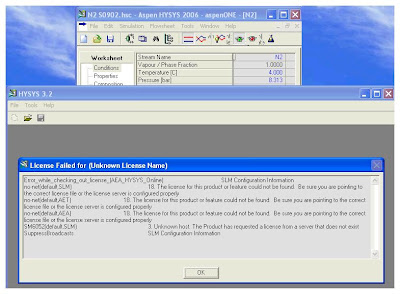
TIPS :
If you have experienced this, one of method to resolve this problem is simply change the file "lshost" to any name (e.g. lshost1). Normally the "lshost" file is located in the HYSYS 3.2 directory (e.g. C:\Program Files\Hyprotech\Hysys 3.2).
Related Topic
If you have experienced this, one of method to resolve this problem is simply change the file "lshost" to any name (e.g. lshost1). Normally the "lshost" file is located in the HYSYS 3.2 directory (e.g. C:\Program Files\Hyprotech\Hysys 3.2).
Related Topic
- aspenONE V2006.5 ... RELEASED
- Lesson Leaned from Installation of SHELL FRED
- Bug in ASPENTECH HYSYS 2006 Dynamic Depressuring Fisher Valve model
- Controlled and Non-controlled Type Depressuring
- How to apply valve equation in HYSYS Depressuring ?
- Simulate Trayed & Packed bed column in HYSYS
- Correct model and thermo package in Amine system simulation using HYSYS
- How to differentiate MASS lower heating value and Volumetric Lower heating value (gas) in HYSYS ?
Labels: HYSYS
Monday, January 28, 2008
Earlier post “Criteria for Requirement of Pressure Relief Device for Tube Rupture” has discussed the criteria for determination of creditability of tube rupture in heat exchanger. For a particular scenario where a Pressure Relief Device (PRD) is required to protect a heat exchanger from tube rupture, there is still issue on the type of PRD to be used.

It is always recommended to provide a Pressure Relief Valve (PRV) to minimize inventory lost to flare and drain disposal system. For a heat exchanger with gas in low design pressure (LPS) side, whenever tube rupture occurred, the gas may provide some “cushion” effect to minimize surge pressure. Thus, a pressure relief valve (PSV) is acceptable in this case.
 However, in the event liquid in LPS side, sudden tube rupture may generate a huge surge pressure to the LPS within a mili-second and results the intermittent peak pressure exceeded design pressure of LPS, pressure relief valve (PRV) is NOT recommended in this case. Pressure relief valve is known to be a “slow acting device”, it may NOT response fast enough to relieve pressure. Thus, a rupture disk which known as “quick acting device” is always recommended in this case.
Nevertheless, there are some researches carried out by HSE UK and reported that there are rupture disks may NOT open quick enough as compare to the surge pressure built-up. Details may refer to :
- Testing and analysis of relief device opening times
- Examination of the effect of relief device opening times on the transient pressures developed within liquid filled shells
Per API STD 521 (2007), section 5.19.3, one-dimensional dynamic modeling / analysis is recommended where there is a wide difference in design pressure between HPS and LPS (e.g. 70 barg and above). A one-dimensional dynamic model is to simulate the pressure profile and pressure transients developed in the exchanger from the time of the rupture which includes tube-rupture fluid dynamic and Pressure relief device response.
Related Topic
- Criteria for Requirement of Pressure Relief Device for Tube Rupture
- Requirement of Overpressure Protection Device on "Final Vessel"
- FREE & reliable Pressure Relief Valve Sizing Software
- Extra Caution When Eliminating Overpressure by Fire Attacks
- Should maximum recommended wall temperature (Tw) for carbon steel vessel used as design temperature ?
- Should we install Butterfly valve for Pressure Relief Valve (PSV) isolation ?
Labels: Overpressure Protection, Pressure Relief Device
Sunday, January 27, 2008
Display problem ? Click HERE

There are many shell & tube heat exchangers used in Oil & Gas production platform and Chemical & Process plants for heat exchange and heat recovery. In many cases the design pressure on shell side and tube side are having large differences (e.g. Water-cooled compressor discharge cooler with 100 barg on gas side (Shell) and 15 barg on water side (tube)). Potential tube leakage or rupture is scenario that shall be engineered during design phase.
A heat exchanger with large design pressure difference between shell and tube side (Shell : 100 barg, Tube 15 barg), a pressure relief device (i.e. PSV & rupture disk) is provided to protect the Low Pressure Side (LPS). However, should a pressure relief device required for a heat exchanger with design pressure of High Pressure Side (HPS) of 18 barg) and LPS of 15 barg ? I noticed that there are still doubt among engineers and heavily discuss.
Criteria for Requirement of Pressure Relief Device for Tube Rupture
We may made reference to API Std 521 - ISO 23251, Fifth edition, Jan 2007 “Pressure-relieving and Depressuring Systems” section 5.9.1
“Complete tube rupture, in which a large quantity of high-pressure fluid flows to the lower-pressure exchanger side, is a remote but possible contingency. Minor leakage can seldom overpressure an exchanger during operation, however such leakage occurring where the low-pressure side is closed-in can result in overpressure. Loss of containment of the low-pressure side to atmosphere is unlikely to result from a tube rupture where the pressure in the low-pressure side (including upstream and downstream systems) during the tube rupture does not exceed the corrected hydrotest pressure (see 3.21 and 4.3.2). The user may choose a pressure other than the corrected hydrotest pressure, given that a proper detailed mechanical analysis is performed showing that a loss of containment is unlikely. The use of maximum possible system pressure instead of design pressure may be considered as the pressure of the high-pressure side on a case-by-case basis where there is a substantial difference in the design and operating pressures for the high-pressure side of the exchanger.”In addition to 5.9.1, engineer shall not miss the second part in section 5.9.2 :
“This type of analysis* is recommended, in addition to the steady-state approach, where there is a wide difference in design pressure between the two exchanger sides [e.g. 7 000 kPa (approx. 1 000 psi) or more], especially where the low-pressure side is liquid-full and the high-pressure side contains a gas or a fluid that flashes across the rupture. Modelling has shown that, under these circumstances, transient conditions can produce overpressure above the test pressure, even when protected by a pressure-relief device. In these cases, additional protection measures should be considered.”
* Dynamic analysisThus, a Pressure Relief Device for tube rupture may NOT required if the following criteria are MET :
- Corrected Test pressure of low pressure side MORE than Design pressure of high pressure side
- Transient peak pressure of low pressure side LOWER than (100%-X%) * Corrected Test pressure of low pressure side
Coming related post...Don't miss
- How to apply Pressure Relief Valve and Rupture Disk for tube rupture service from action perspective ?
- Confusion on Two-third (2/3) rule or Ten-thirteen (10/13) rule
- Requirement of Overpressure Protection Device on "Final Vessel"
- FREE & reliable Pressure Relief Valve Sizing Software
- Useful Documents Related to Pressure Relief Valve (PRV) - Part 3
- Useful Documents Related to Pressure Relief Valve (PRV) - Part 2
- Useful Documents Related to Pressure Relief Valve (PRV) - Part 1
- Extra Caution When Eliminating Overpressure by Fire Attacks
- Should maximum recommended wall temperature (Tw) for carbon steel vessel used as design temperature ?
- Should we install Butterfly valve for Pressure Relief Valve (PSV) isolation ?
Labels: Overpressure Protection, Pressure Relief Device
Saturday, January 26, 2008

Nowadays, sweet field is getting less and less. Oil and gas activities are moving into exploration and production of high Carbon Dioxide, high mercury and sour field. One of the example is recent project on a gas field development which contains very high carbon dioxide (~ 40% CO2), reasonably high Hydrogen Sulphide (>120ppm h2S), high mercury level (> 5000 microgram/Nm3 at 25 barg) and high sand production (> 2 kg/h) as discussed in "Several Concerns in High CO2 Field Development".
With present exploration & production environment, minimizing release of CO2 to atmosphere and injection into reservoir is for well maintenance and disposal is generally encouraged. Release of of H2S to atmosphere is prohibited. H2S is normally injected together with Co2 gas or recover to produce sulphur (S) as by product. Handling sulphur in powder form potential poses the danger of fire or possibly dust explosions.
Another article (by BARTEC) "Dust Explosion Protection" would bring some additional information on dust explosion.
One of the recommended standard for prevention of fire and dust explosion is NFPA 654 – Standard for the Prevention of Fire and Dust Explosions from the Manufacturing, Processing, and Handling of Combustible Particulate Solids. You may visit NFPA website to obtain a formal copy.
While dealing with dust explosion and NFPA 654, the following questions may be raised :
Related Topic
With present exploration & production environment, minimizing release of CO2 to atmosphere and injection into reservoir is for well maintenance and disposal is generally encouraged. Release of of H2S to atmosphere is prohibited. H2S is normally injected together with Co2 gas or recover to produce sulphur (S) as by product. Handling sulphur in powder form potential poses the danger of fire or possibly dust explosions.
"Eighty percent of all industrial dusts are combustible, and even a dust layer of 1 mm in a closed room is sufficient to trigger an explosion when the dust is swirled up and ignited. These facts, combined with the fact that those affected are not sufficiently aware of the danger (in contrast to the danger of gas explosions) underlines the importance of preventing dust explosions. "What is dust explosion ? What are the factors affecting dust explosion ? What are the protection measures ? How to selection equipment dealing with powder from dust explosion perspective ?... The following article (by STAHL) will help you analyse the danger of a dust explosion in your facilities and to take the suitable technical and organisational steps to minimise this risk.
Another article (by BARTEC) "Dust Explosion Protection" would bring some additional information on dust explosion.
One of the recommended standard for prevention of fire and dust explosion is NFPA 654 – Standard for the Prevention of Fire and Dust Explosions from the Manufacturing, Processing, and Handling of Combustible Particulate Solids. You may visit NFPA website to obtain a formal copy.
While dealing with dust explosion and NFPA 654, the following questions may be raised :
- What is NFPA 654 and how does it affect my plant?
- Who is responsible for implementing NFPA 654 standards at the plant?
- What explosion protection methods are required by NFPA 654?
- How do I begin the process protection design to comply with NFPA 654?
- What process equipment is covered by NFPA 654 ?
- All of my process equipment has deflagration venting installed on it. Is that all I have to do?
- Does ‘return air’ to the plant from an air separation device present a danger?
- Where should I consider the use of building vents?
Related Topic
- Several Concerns in High CO2 Field Development
- Correct model and thermo package in Amine system simulation using HYSYS
- How does Supercritical fluid looks like ?
- Canada Aim For 20% cut in CO2 emissions by 2020
- OGT - Others FREE articles related to Amine & CO2...
- Optimized Gas Treating, Inc. (OGT) - Experts in CO2-Amine
Thursday, January 24, 2008
 Recently i have discussed some issue related to system depressuring with some engineers. One of the topic where we were arguing about was the time limit on the depressuring. These engineers keep on stating that the emergency depressuring system shall be designed to depressure the facilities to 50% of its design pressure or 6.9 barg within 15 minutes.
There are many oil and gas company are practicing this approach. Above statement has been clearly stated in the company design manual. Many engineers has simply used above as criteria without confirming stress induced by internal pressure during the depressuring process upon allowable stress by the weakest component within the system.
API RP 521 Edition Fourth, "Pressure-relieving and Depressuring Systems" section 3.19 has a statement
API RP 521 Edition Fourth, "Pressure-relieving and Depressuring Systems" section 3.19 has a statement
"...A vapor depressuring system should have adequate capacity to permit reduction of the vessel stress to a level at which stress rupture is not of immediate concern. For sizing, this generally involves reducing the equipment pressure from initial conditions to a level equivalent to 50% of the vessels design pressure within approximately 15 minutes..."Many engineers has only considered the second part of the statement.
With the issuance of API Std 521 - ISO 23251, Edition Five, Jan 2007, "Pressure-relieving and Depressuring Systems". In section 5.20, it clearly stated that
"...In order to be effective, the depressuring system shall depressure the vessel such that the reduced internal pressure keeps the stresses below the rupture stress. "
Similar to earlier revision (1997), the time limit of 15 minutes is not a criteria. However, an example cited 15 minutes for a particular material and vessel was exposed to pool fire condition.
A depressuring system shall be designed such that the stress resulted by internal pressure shall always below the rupture stress (included fire scenario). This approach has been adopted for many cases and it appear that those thick wall vessel (more than 90 mm wall thickness) would allow longer than 15 minutes depressuring time. Medium wall thickness vessel (30-90mm) would see depressuring in the range of 3-15 minutes. While those vessel with wall thickness (less than 30 mm) would experience less than 3 minutes of depressuring. This leads to an excessive depressuring load and flare capacity.
Updated : Dec 2008
Updated : Dec 2008
Related Topic
- Bug in ASPENTECH HYSYS 2006 Dynamic Depressuring Fisher Valve model
- Another descrepancy found in API Std 521Jan 2007
- Controlled and Non-controlled Type Depressuring
- How to apply valve equation in HYSYS Depressuring ?
- ERRATA - API Std 521, Pressure Relieving and Depressuring Systems
- Why Restriction Orifice is some distance from Blowdown valve ?
- Should we consider JET FIRE for Pressure Relief Valve (PSV) load determination ?
Labels: Depressurization, Overpressure Protection
Wednesday, January 23, 2008

Pump India is a bi-monthly magazine on PUMP industry since 12 years ago and this magazine circulated all over INDIA and abroad. Many process and /or mechanical engineer may aware of this magazine. Read the details about this magazine.
There is an article "Tips on Centrifugal Pump" which has presented over 30 tips for centrifugal pump from pump selection, installation, operation and maintenance. I think this would be a pretty simple but useful tips to designer, operation engineer and maintenance engineer. Personally i have gain some extra new insights about pump after gone through it this morning.

In addition, there is another article "Useful Pump Data" which has presented some new clues and simple rule-of-thumb related to pump. You may get one or two clues in this article.
Related Post
There is an article "Tips on Centrifugal Pump" which has presented over 30 tips for centrifugal pump from pump selection, installation, operation and maintenance. I think this would be a pretty simple but useful tips to designer, operation engineer and maintenance engineer. Personally i have gain some extra new insights about pump after gone through it this morning.
In addition, there is another article "Useful Pump Data" which has presented some new clues and simple rule-of-thumb related to pump. You may get one or two clues in this article.
Related Post
- Crane Technical Paper No. 410 - Example Workbook
- Fundamentals of Compressible Flow - FREE Textbook
- Hydraulic Design Of Liquid with Pump Circuit - A revision kit...
- Hydraulic Design of Liquid Piping Systems - A revision kit...
- Why bypass Non-Return Valve (NRV) ?
Labels: Fluid Flow, Hydraulic, Pump
Tuesday, January 22, 2008

There are many young design engineer will experience or has experienced gas - liquid separator sizing. In most cases, a mist eliminator is used to trap small liquid droplet entrained in the gas. Now the engineer may experience difficulties in answering the following questions :
- What type of mist eliminator (e.g. mesh pads, vane pack, etc) should be used ?
- What are the advantages and disadvantages of mesh pad and vane pack ?
- How mesh pads and vane pack trap liquid droplet ?
- What is the liquid capture efficiency of mesh pad and vane pack ?
- How droplet size, mesh strand diameter, gas velocity, liquid density, gas density, gas viscosity, mesh pad/vane pack design affecting liquid capture efficiency ?
- What is the limit of mesh pad compare to vane pack ?
- How do i size mesh pad or vane pack mist eliminator ?
- What are the geometry and installation requirement of separator with mist eliminator ?
- ...etc
Although this article may assist you in determining the type of mist eliminator, dimension, mist eliminator thickness, gas flow area, etc using a recommended design Souders-Brown vapor load factor (K), however there are still many other type of mist eliminator (MistFix insertion mist eliminator, double-pocket vane pack, which potentially result better removal efficiency and cost effective as compare to ordinary mesh pads and vane pack. In addition, the graph is tested with air-water mixture, it may have some deviation with actual process fluid. The deviation could be insignificant or very significant.
You may use above proposed method for PRELIMINARY sizing in order to get a quick separator dimensioning, the detail selection and calculation shall be conducted by mist eliminator supplier with their proprietary graph and correction parameters.
In many real world examples, the mist eliminator thickness would be in the range of 4"-6". Thus, you may use this PRELIMINARY thickness in quick separator dimensioning.
Related Topic
- AMISTCO (P2) - Extensive info on Mist eliminator, knitted mesh, random & structured packing, distillation
- AMISTCO (P1) - Extensive info on Mist eliminator, knitted mesh, random & structured packing, distillation
- KnitMesh...Good Articles on Mist eliminator still available FREE...
- ACS - Design manual for Mist Eliminators, Trays, Packing, Internals...All in distillation columns
Labels: Mist Eliminator, Separation, Separator
Monday, January 21, 2008
In earlier post "Useful Documents Related to Control Valve" there are number very useful documents related control valves.
There are two good articles have been added in the same post.
PLANT DESIGN & CONTROL VALVE SELECTION UNDER INCREASING COST & TIME PRESSURE
Dipl. Ing. Holger Siemens
Samson AG
This article is split into two parts: broadly speaking, part one looks at control valve operating points and provides a case history involving a mismatch. The author introduces better valve sizing practices and uses this theory to resolve the problems introduced in the case history. Part two (scheduled for the June issue) starts by explaining the trends and definitions of inherent valve characteristics before focusing on, "quick and dirty" sizing. The paper then addresses cavitation before concluding with the expert software CONVAL to help select the optimum valve characteristic form. Part two starts by explaining the trends and definitions of inherent valve characteristics before focusing on "quick and dirty" sizing. The paper then addresses cavitation before concluding with the expert software available to help select the optimum valve characteristic form.
CONTROL VALVE DESIGN ASPECTS FOR CRITICAL APPLICATIONS IN PETROCHEMICAL PLANTS
Dipl. Ing. Holger Siemens
Samson AG
This paper reviews the past, present and future of valve design and sizing, taking all-important issues such as increasing cost pressure and time pressure into account. This paper is presented in two parts: firstly, how to use manufacturer independent softwre to analyze given or calculated plant parameters in more detail from an overall point of view with a complete power check and optimizing possibilities. Some case studies are also discussed. The second section, scheduled for a future issue, includes information on to design, size and use severe service control valves with good performance for long maintenance intervals. Different philosophies of valve design (plug design), pressure balance systems, stem sealing, actuator sizing, cost philosophies for "high end" applications are discuss. The second and third sections presents information on design, size and use of severe service control valves, the kind of troubles that can be predicted with control valve sizing as well as suggestions for troubleshooting control valve failures.
VALVE SIZING & SELECTION TECHNICAL REFERENCE
Warren Controls
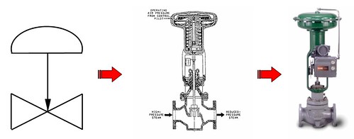
A Control Valve performs a special task, controlling the flow of fluids so a process variable such as fluid pressure, fluid level or temperature can be controlled. In addition to controlling the flow, a control valve may be used to shut off flow. A control valve may be defined as a valve with a powered actuator that responds to an external signal. The signal usually comes from a controller. The controller and valve together form a basic control loop. The control valve is seldom full open or closed but in an intermediate position controlling the flow of fluid through the valve. In this dynamic service condition, the valve must withstand the erosive effects of the flowing fluid while maintaining an accurate position to maintain the process variable.
Click HERE to revisit the original post.
Related Topic
There are two good articles have been added in the same post.
PLANT DESIGN & CONTROL VALVE SELECTION UNDER INCREASING COST & TIME PRESSURE
Dipl. Ing. Holger Siemens
Samson AG
This article is split into two parts: broadly speaking, part one looks at control valve operating points and provides a case history involving a mismatch. The author introduces better valve sizing practices and uses this theory to resolve the problems introduced in the case history. Part two (scheduled for the June issue) starts by explaining the trends and definitions of inherent valve characteristics before focusing on, "quick and dirty" sizing. The paper then addresses cavitation before concluding with the expert software CONVAL to help select the optimum valve characteristic form. Part two starts by explaining the trends and definitions of inherent valve characteristics before focusing on "quick and dirty" sizing. The paper then addresses cavitation before concluding with the expert software available to help select the optimum valve characteristic form.
CONTROL VALVE DESIGN ASPECTS FOR CRITICAL APPLICATIONS IN PETROCHEMICAL PLANTS
Dipl. Ing. Holger Siemens
Samson AG
This paper reviews the past, present and future of valve design and sizing, taking all-important issues such as increasing cost pressure and time pressure into account. This paper is presented in two parts: firstly, how to use manufacturer independent softwre to analyze given or calculated plant parameters in more detail from an overall point of view with a complete power check and optimizing possibilities. Some case studies are also discussed. The second section, scheduled for a future issue, includes information on to design, size and use severe service control valves with good performance for long maintenance intervals. Different philosophies of valve design (plug design), pressure balance systems, stem sealing, actuator sizing, cost philosophies for "high end" applications are discuss. The second and third sections presents information on design, size and use of severe service control valves, the kind of troubles that can be predicted with control valve sizing as well as suggestions for troubleshooting control valve failures.
VALVE SIZING & SELECTION TECHNICAL REFERENCE
Warren Controls
A Control Valve performs a special task, controlling the flow of fluids so a process variable such as fluid pressure, fluid level or temperature can be controlled. In addition to controlling the flow, a control valve may be used to shut off flow. A control valve may be defined as a valve with a powered actuator that responds to an external signal. The signal usually comes from a controller. The controller and valve together form a basic control loop. The control valve is seldom full open or closed but in an intermediate position controlling the flow of fluid through the valve. In this dynamic service condition, the valve must withstand the erosive effects of the flowing fluid while maintaining an accurate position to maintain the process variable.
Click HERE to revisit the original post.
Related Topic
- Useful Documents Related to Control Valve
- Hydraulic Design Of Liquid with Pump Circuit - A revision kit...
- Hydraulic Design of Liquid Piping Systems - A revision kit...
- Why bypass Non-Return Valve (NRV) ?
Labels: Control valve, Ebook, Learning
Sunday, January 20, 2008
Display problem ? Click HERE

Crane Technical Paper No. 410 (TP-410) is one of the most comprehensive guide for flow of fluid through valves, pipes and fittings. An engineer dealing to design as well as operation of plant valves, fittings and piping should aware of this technical paper.
It has been developed since 1942 and continues update with new information...You may get a copy of TP-410 from Crane Valve Group (CVG).
In this technical paper, there are many real world examples. A student or fresh engineer will expose these practical examples. One of the Guru in Chemical & Process Engineering, Mr. Art Montemayor who has been practicing engineering for passed 48 years and now still active in forum such as CheResources forum, Eng-tips, etc has spent his time programmed these examples in EXCEL sheet. With his kindness, he has shared his work full of examples (programmed) in the CheResources forum.
You may download from CheResources forum via this post. You shall be the forum member in order to download this valuable EXCEL sheet. It only take you 5-10 minutes to register (FREE) as member. QUICK ! Don't miss this valuable workbook !
CheResources forum Member... Download from here
Non Member... Register and download.CheResources forum Member... Download from here
This first released workbook consist of 30 examples where only 7 examples are still work in progress. In addition, it also has Moody chart, Pipe tables, Quick size for water line, water density and steam data.
Related Post
- Fundamentals of Compressible Flow - FREE Textbook
- Hydraulic Design Of Liquid with Pump Circuit - A revision kit...
- Hydraulic Design of Liquid Piping Systems - A revision kit...
- Why bypass Non-Return Valve (NRV) ?
- Generalised model to predict pressure drop and capacity of countercurrent gas/liquid packed column
Labels: Fluid Flow, Hydraulic
Friday, January 18, 2008
Nano technology is getting important nowadays. Special characteristic of nano material such as high thermal conductivity, high electrical conductivity, high strength, etc would definitely will bring a great revolution in material selection and change the way we doing things.
There is a great detail introduction and substantial links to other websites related to nano-technology in here.
Let see simple presentation by Dr. Julie MacPHERSON, a researcher intended to find the way to produce nano-carbon in most affordable cost.
Related Post
- Euro 6 Million Supporting Nanotechnology
- Nanowire battery... High Potential of Replacing Lithium Battery
- Nanowerk - NanoTech News & Database Center
- Pitting Corrosion - Mechanism & Prevention
- How a Chloride Stress Corrosion Cracking Lookslike ?
- Chloride Stress Corrosion Cracking & Use correct MOC for seawater service
- Unified Numbering System for Metals and Alloys
Labels: Material, NanoTech, Technology
Thursday, January 17, 2008
Display problem ? Click HERE
This post is just to capture what has been discussed recently on "Why a globe valve is located downstream of manual block valve on drain line ?" in Eng-Tips forum.

A maintenance drain line is typically consists of a block valve (ball or gate subject to service) and a globe valve. Block valve is provided for isolation purposes while globe valve for throttling to avoid excessive flow to closed drain system.
Drain minimum line size is typically 2" (typical but may be different elsewhere). Sudden opening of 2" block valve would results excessive flow to close drain system and potentially leads to high noise level, acoustically induced vibration, erosion-corrosion, etc. A globe valve is provided on the drain line to limit sudden large flow into closed drain line.
Other than above mentioned consequences, pressure drop across globe valve will results low temperature (lower than zero degC) due to JT effect. Manual block valve located downstream of globe valve would experience similar temperature and leads to ice form at valve body, stem, shaft, etc. This would disable re-closure of the manual block valve. Thus, it is always advisable to locate manual block valve upstream of globe valve.
In earlier post (Why Restriction Orifice is some distance from Blowdown valve ?), discussed about the Blowdown valve and restriction orifice. Similarly the cold temperature may extends from globe valve to block valve which located upstream. Thus, it is always advisable to provide minimum 600 mm between block valve and globe valve.
As good operation practices, it is always advisable to minimize excessive flow through proper draining procedures. Normally the draining activities would be carried out in the following sequences :
- transfer liquid to next drum until drum to be drained is at minimum level
- depressurized pressure to about 2-3 barg
- then only drain the inventory
- to accelerate draining activity, nitrogen would be used to maintain a good positive pressure (2-3 barg) in the drum
Related Post
- Hydraulic Design Of Liquid with Pump Circuit - A revision kit...
- Hydraulic Design of Liquid Piping Systems - A revision kit...
- Why bypass Non-Return Valve (NRV) ?
- Why Restriction Orifice is some distance from Blowdown valve ?
- Workbook for Chemical Reactor Relief System Sizing
- A must have book...Emergency Relief System Design Using DIERS Technology
- Requirement of overpressure protection devices on system design to PIPING code
Wednesday, January 16, 2008
Display problem ? Click HERE
 ASPENTECH has just released it aspenONE V2006.5 on Jan 16th 2008. aspenONE user is encourage to upgrade (upon request) their present version to enjoy the following features.
- Superior aspenONE integration enables better cross-application workflows
- Vista compatibility exploits the latest Microsoft OS release
- Improved quality and reliability optimize performance
- New features and enhancements simplify usability
- Improved online help saves valuable time
- Updated documentation and training ensure faster deployment
 USEFUL INFORMATION :
- Read more about aspenONE (Click HERE).
- What's new about aspenONE V2006.5 ? (For user only - Click HERE)
- AspenTech Software Upgrades and Licenses
One of the objective of upgrading a software is to use a bug-FREE / bug-rectified software. Many experiences shown that upgraded version creates NEW bug due to bugs removal activities. This has really made feel uneasy whenever a project demand for upgraded version.
What is your experience ?
Related Post
What is your experience ?
Related Post
- Bug in ASPENTECH HYSYS 2006 Dynamic Depressuring Fisher Valve model
- Controlled and Non-controlled Type Depressuring
- How to apply valve equation in HYSYS Depressuring ?
- Simulate Trayed & Packed bed column in HYSYS
- Correct model and thermo package in Amine system simulation using HYSYS
- How to differentiate MASS lower heating value and Volumetric Lower heating value (gas) in HYSYS ?
- Paul Muller - Process Solution Provider...@Heat Exchanger
- Optimized Gas Treating, Inc. (OGT) - Experts in CO2-Amine
- ChemSep™ LITE - FREE Distillation, Absorption & Extraction Simulation
Tuesday, January 15, 2008
"API 14C SAC A.4.c.5 seems to indicate that a PSV is required on a pressure vessel (max pressure >5 psig) unless it is the final vessel on a flare header (i.e. Flare KO Drum). However, this implies that any other vessel venting into the flare header (e.g. Closed Drain Sump) needs a PSV to protect against blockage of the final vessel."Recommended :
- Subscribe FREE - Processing Magazine

My personal opinion is if the connection between Closed Drain Sump and Flare KO Drum has NO internal that potentially create blockage which lead to overpressure scenario and affecting relief path, a Pressure relief device is not required on the Closed Drain Sump even though it is not the "final vessel". This is inline with the API14C SAC A.4.C.4.
The following examples show an overpressure protection device is required even though the pressure vessel is "final vessel"
a) Degassing drum with vent line and flame arrester discharge to atmosphere
This drum is a "final vessel" in the relieving path. However there is a potential of flame arrester blockage and may lead to overpressure of this drum. Thus, an overpressure protection device is required. Normally a Pressure relief valve or rupture disk is installed across the flame arrester. In this case, it is inline with the API14C SAC A.4.C.1.
b) Flare KO Drum with Flare Recovery system
In certain environment sensitive area, "zero emission" and As-Low-As-Reasonable-Practical (ALARP) principle are adopted. Those in most cases, a Flare Recovery System (FRS) will be implemented in Flare system. It could be a recovery compressor, ejector, etc. In most cases, the Flare KO Drum downstream flare line which connected to flare stack may have an on-off valve to facilitate plant maintenance. Under this case, eventhough the Flare KO Drum is the "final vessel" but an overpressure protection device (i.e. rupture disk) would be installed across the on-off valve to ensure a clear relief path. In this case, it is inline with the API14C SAC A.4.C.1.
The following examples show an overpressure protection device may NOT required even though the pressure vessel is NOT "final vessel"
a) Two drums connected together with no internal in the interconnecting pipe
As there is NO possibility existent of potential blockage on the interconnecting line and the overpressure protection device located at downstream has been designed for worst case (of two drums), an overpressure protection device is NOT required for the upstream drum. In this case, it is inline with the API14C SAC A.4.C.4.
b) Flare KO Drum with Water Seal Drum
As large relief will destroyed the water seal in the seal drum, thus there is NO possibility existent of potential blockage results overpressure scenario. Overpressure protection device is NOT required for the Flare KO drum. In this case, it is inline with the API14C SAC A.4.C.5.
If you can think of any typical example, let share it in this post.
Related Post
- FREE & reliable Pressure Relief Valve Sizing Software
- Useful Documents Related to Pressure Relief Valve (PRV) - Part 3
- Useful Documents Related to Pressure Relief Valve (PRV) - Part 2
- Useful Documents Related to Pressure Relief Valve (PRV) - Part 1
- Should maximum recommended wall temperature (Tw) for carbon steel vessel used as design temperature ?
- Should we consider JET FIRE for Pressure Relief Valve (PSV) load determination ?
Labels: Loss Prevention, Overpressure Protection, Pressure Relief Device
