Thursday, May 21, 2009
Addendum May 2008
API has released the Addendum details to API Std 521. It describes in detail the modified sections compare to earlier release in 2007. You may download Addendum May 2008 from here.
Errata June 2007
For those who don't not aware the Errata in June 2007 for API Std 521 released in 2007, you may read "ERRATA - API Std 521, Pressure Relieving and Depressuring Systems" and download Errata June 2007 from here.
Related Topic
- API Std 521 ADDENDUM, MAY 2008 - Check Out Revised Section
- ERRATA - API Std 521, Pressure Relieving and Depressuring Systems
- Workbook for Chemical Reactor Relief System Sizing
- A must have book...Emergency Relief System Design Using DIERS Technology
- Requirement of overpressure protection devices on system design to PIPING code
- Discussion on ISENTROPIC and ISENTHALPIC process via Relief Valve
Labels: Depressurization, Loss Prevention, Overpressure Protection, Pressure Relief Device
Sunday, January 25, 2009
Subscribe FREE - Processing Magazine
 Depressuring system is provided in Oil and gas, Gas & LNG plant, etc to evacuate the inventory from process system as fast as possible so that the reduced internal pressure stresses is kept below the rupture stress. This has been discussed in "Depressuring within 15 minutes no longer applicable ?". Nevertheless, quick depressuring may lead to other problem such as low temperature embrittlement, excessive noise and vibration, etc. Depressure a high pressure would lead to low temperature of depressured system and failure due to low temperature embrittlement. Higher the depressuring rate, lower the temperature can be experienced by depressured system. Thus, the restriction orifice (RO) downstream of Blowdown Valve (BDV) in depressuring system primarily is to limit flow so that the temperature will not drop below the allowable lowest temperature limit of material. This has been discussed in "Don't misunderstood depressuring".
Although depressuring shall be implemented within the shortest time possible, excessive depressuring may potentially lead to damage to equipment such as compressor seal, solid bed, etc. Thus, there are two type of depressuring as discussed in "Controlled and Non-controlled Type Depressuring". Nevertheless, it is emphasized again here, depressuring system shall be designed to bring plant to safe level without any tolerance.
Many depressuring systems are designed to depressure the system within 15 minutes follow recommendation in API 521. Nevertheless, one shall take note that the 15 minutes is sort of arbitrary and may be good for some system and configuration. Thus, in most recent API STD 521, the requirement has slightly changed where a depressuring system shall be designed such that the stress induced by internal pressure of a system is lower than stress allowable by the system. This may lead to shorter depressuring time as discussed in "Depressuring within 15 minutes no longer applicable ?".
 Depressuring can be conducted using simple depressuring module in process simulator such HYSYS, PRO-II, etc. One shall understood there are limitation and accuracy issue in above mentioned depressuring modules and shall be used with care. There are other depressuring simulator such as LNGDYN by TECHNIP, BLOWDOWN by Imperial College, etc which are calculated rigorously and tested with real plant data. It is always advisable to use these simulator for specific case.
Assumption
In this post, a manual depressuring method is introduced. This method is first introduced by Grote and are derived base on following assumptions :
i) Critical flow throughout entire depressuring process
ii) Constant mass flow throughout entire depressuring process
iii) System being depressured is maintained as gaseous throughout entire depressuring process
iv) Constant temperature, molecular weight and compressibility
Methodology
Following is the derivation of the manual equation.


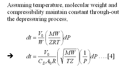

Equation [5] may be used for manual depressuring if a system inventory (initial mass, M0), depressuring time (t), initial (P0) and final pressure (P) are are known. One shall check the assumptions are valid before it is used. This equation may be used as quick method to determine the depressuring flowrate for quick estimate, however it is not recommended during detailed design.
- Additional Concerns in Controlled Depressuring
- Depressuring - Save Some Time in HYSYS - FLARENET Iteration
- Few Recommendation on Manual Blowdown Line
- A refresh to Process Engineer on few phenomenons in restriction orifice
- Bug in ASPENTECH HYSYS 2006 Dynamic Depressuring Fisher Valve model
- How to apply valve equation in HYSYS Depressuring ?
- Why Restriction Orifice is some distance from Blowdown valve ?
Labels: Depressurization, HYSYS
Wednesday, January 7, 2009
Subscribe FREE - Processing Magazine
Depressuring system is commonly provided in Oil and gas facilities to facilitate system inventory blowdown to a safe level within a reasonable time during emergency situation. Detail requirements may refer to API Std 521 section 5.20.1. Conventionally depressuring system consist of Blowdown Valve (BDV) with Restriction Orifice (RO) located some distance (about 600mm) downstream of BDV. Read "Why Restriction Orifice is some distance from Blowdown valve ?" to understand more the distance requirement. Beside, there are controlled and non-controlled Type Depressuring. Second type of non-controlled depressuring is a throttling device with control function into it.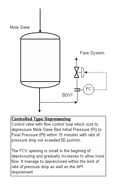
Recently some smart engineers have proposed to use the second type with throttling device to replace the conventional BDV (ball valve) plus RO type based on following reasons :
- Ball valve opens too quickly which may cause bending of RO leading to size changes and higher flow on next use.
- Ball valve does not throttle flow and opening will erode the ball & sealing. Globe valve, with soft seats, will have minimal damage and can also be used for pressure control.
- Globe valve with control function will increase the blowdown rate with gradual opening in later stage
High flow leading to bending of RO and subsequently cause higher flow and low temperature issue of blowdown vessel might be one of the credible concern in conventional BDV plus RO system. Beside, erosion & cavitation occured at the RO possibily lead to larger RO. Althought this concern is valid, however there are minimium (almost none) reported case in the failure of RO in this regard. The could be credited to a infrequent use, proper blowdown rate determinination, correct material selection, properly calcuated RO bore size.
Conventionally a valve with control function will be sized to open at 75-85%. With the characteristic of valve i.e. equal percentage and remaining 15-25% opening would results a flow of 2-3 time when it is FULLY OPEN. Employing a globe valve with control function, whenever the control function is failed and derive a maximum signal to open the glove valve fully, it will results excessive flow to the downstream disposal system. Large and costly disposal system is expected.
Difficult Valve Characteristic Selection
If a quick opening valve is selected to reduce the large flow during valve full open , this will partially cause inefficient control during low flow. Additional effort is required on valve characteristic selection.
Reliability, Availability & Cost Effective
Reliability and Availability of blowdown with control valve is another concern. Conventional BDV (ball valve) is spring to open, double solenoid valves, volume bottle, high SIL Blowdown system lead to increase safety integrity. Use of control valve may experience difficultites in meeting the safety integrity or high cost is incurred. Thus, a proper relaibility, availability and cost effective solution may have to considered.
Concluding remark
Above proposal certainly a good idea to be investigated in detail as there is a great potential in assisting system blowdown in shorter time and reduce overall safety risk. A proper discussion shall be included to address the issue as highlighted above in order to provide a cost effective but not tolerating any safety concerns.
Related Post
- Few Recommendation on Manual Blowdown Line
- A refresh to Process Engineer on few phenomenons in restriction orifice
- Bug in ASPENTECH HYSYS 2006 Dynamic Depressuring Fisher Valve model
- Controlled and Non-controlled Type Depressuring
- How to apply valve equation in HYSYS Depressuring ?
- Why Restriction Orifice is some distance from Blowdown valve ?
- Restrcition Orifice Used in Many Applications in Different Manners
Labels: Depressurization, Overpressure Protection
Sunday, November 23, 2008
A reader MT (abbre.) has read "Why Restriction Orifice is some distance from Blowdown valve ?" and drop me a note. The question are more-or-less as follow :Original Intention
Responses
Related Post
- Few Recommendation on Manual Blowdown Line
- A refresh to Process Engineer on few phenomenons in restriction orifice
- Bug in ASPENTECH HYSYS 2006 Dynamic Depressuring Fisher Valve model
- Controlled and Non-controlled Type Depressuring
- How to apply valve equation in HYSYS Depressuring ?
- Why Restriction Orifice is some distance from Blowdown valve ?
Labels: Depressurization, Material, Overpressure Protection, Safety
Tuesday, September 16, 2008
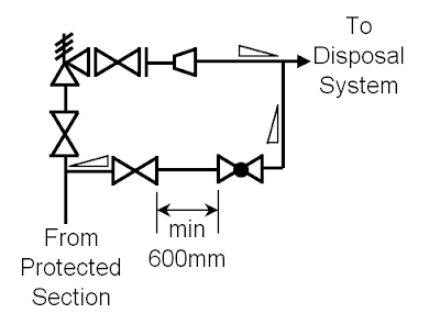
If you have worked on P&ID, you probably have seen an isolation valve with a globe valve across a pressure relief valve (PRV). See below image.
- Subscribe FREE - Chemical Engineering
- Tips on Succession in FREE Subscription

Many engineer may have aware of this purpose of this line. This arrangement is a manual blowdown line. It is normally used system inerting during start-up and system purging during shutdown maintenance. As the source of the inventory is same as PRV i.e. vessel and the discharge location is same i.e. flare, thus it is generally drawn in P&ID as such. Similarly it also being arranged in parallel with PRV in actual installation.
Some engineers may understand the main purpose of this arrangement but somehow mis-called it as PRV bypass. It is pretty same as the control valve (CV) bypass arrangement. In reality operator can operate the CV bypass and throttle the flow manually by the bypass globe valve while operator take out the control valve for maintenance purpose. However, operator is absolute not allowed to bypass the PRV. When designer write the operating manual, the correct terms shall be used to avoid any misunderstanding. This could be a minor error however sometime it is important.
Some recommended features associate with this arrangement are as follow :
- The isolation valve and globe valve shall be arranged such that no low pocket present as liquid possible present in low pocket promote corrosion
- These arrangement install at high point so that liquid is sloping away from them
- Maintain a distance i.e. 600mm between isolation valve and globe valve to avoid isolation valve stuck open during manual blowdown. See reasoning in "Why Restriction Orifice is some distance from Blowdown valve ?"
- The recommended size of the line and valve is 2". If size smaller then 2" is used, concern of severe vibration of small bore connection (SBC) shall be addressed.
- The short line downstream of globe valve to connection is recommended to design to MACH number lower than unity (1) i.e. 0.8 when the globe valve is fully open. This is to avoid operator inadvertently open the globe valve.
- The downstream piping shall be sufficiently thick to ensure it is failed on acoustically induced vibration.
- The isolation valve may be Normally Closed (NC). However, losing inventory due to inadvertently open of this blowdown valve is deem to be a concern, the isolation valve may be Car Sealed Close (CSC) or Locked Close (LC).
- Prior to any blowdown, the operator may leave the upstream system settle out. This allow the internal fluid temperature cooled to minimum possible ambient temperature. Manual blowdown after settled out would lead to very low temperature downstream of globe valve. Thus the low temperature during manual blowdown shall be studied to ensure the material will not failed on low temperature embrittlement.
- If the fluid is having high pour point, solidify or crystallize under minimum ambient temperature, etc, may consider insulating and/or heat trace the line.
Although above manual blowdown line is pretty simple, there are still features associate with it. Above is non-exhaustive list of features. If you find any special conditions, welcome your advice and comments.
Related Post
- A refresh to Process Engineer on few phenomenons in restriction orifice
- Bug in ASPENTECH HYSYS 2006 Dynamic Depressuring Fisher Valve model
- Controlled and Non-controlled Type Depressuring
- How to apply valve equation in HYSYS Depressuring ?
- Why Restriction Orifice is some distance from Blowdown valve ?
- Restrcition Orifice Used in Many Applications in Different Manners
- How to Resolve Issue with PSV Inlet Line Loss Exceeded 3% of Set pressure
- Few Concerns & Recommendations of PSV Discharge Tail pipe
- Few Concerns & Recommendations on PSV INLET line
Labels: Depressurization, Overpressure Protection, Pressure Relief Device
Wednesday, August 27, 2008
- Tips on Succession in FREE Subscription
- Subscribe FREE - Processing & Control News
 "I was doing Depressuing using HYSYS and flare network back pressure calculation using FLARENET for conventional Blowdown valves with restriction (BDV/RO). Peak flow of Depressuring unit in HYSYS which obtained from initial depressuring and based on initial depressuring pressure to Atmospheric pressure, is used as input to FLARENET.
I have two questions :
What I really concerned is back pressure calculated from FLARENET is higher than ATM, is the back pressure will affect the peak flow ?
First far most important thing is that there will be total plant or segregated zone blowdown. This type of blowdown will results simultaneous opening of all BDVs within a zone and simultaneous blowdown of multiple sections. One shall not consider SINGLE BDV opening ONLY. Simultaneous blowdown will results high total blowdown rate and induced high back pressure to each BDV / RO within the blowdown zone.
In many events, the flow passing the RO is CRITICAL flow where the back pressure from flare network is lower than the fluid critical pressure (Pc). Read more in "A refresh to Process Engineer on few phenomenons in restriction orifice". Under critical flow condition, the back pressure has no impact to the flow rate passing through the RO (assume backpressure does not affect the vena contracta cross sectional area). Thus, peak flow calculated in HYSYS depressuring unit considering backpressure of ATM is still remain same if the backpressure (Pb) is lower than critical pressure (Pc).
However, for many rare cases when the system pressure is low, hence the critical is much lower. This potentially results back pressure high than critical pressure and cause SUBCRITICAL flow condition. Under this condition, backpressure has impact to the peak flow calculated by HYSYS.Knowing back pressure may affect peak flow under subscritical flow condition, some level of checking and iteration may required.
Iteration as proposed above could be very time consuming and not all the BDV/RO required iterate update. Infact only those BDV/RO experiencing Subcritical flow would need to involve in the iteration process.
The following steps may be considered :
i) For initial step, use ATM in HYSYS for depressuring to estimate the peak flow
ii) Peak flow estimated in HYSYS will be entered into FLARENET to calculate back pressure at each BDV/ROs.
iii) Compare each BDV/RO Critical pressure (Pc) and Back pressure (Pb). If Pc is higher than Pb, that particular BDV/RO need not involve in the iteration.
iv) Identify those BDV/RO with Pc less than Pb. Re-adjust back pressure in HYSYS base on calculated Pb from FLARENET to obtain a new peak flow.
v) Reenter and rerun in FLARENET.
vi) Repeat step (iii) to (v) till backpressure in HYSYS and FLARENET are matched.
Above will significantly reduce the iteration time.
Related Topic
- Don't misunderstood depressuring
- Depressuring within 15 minutes no longer applicable ?
- Bug in ASPENTECH HYSYS 2006 Dynamic Depressuring Fisher Valve model
- Controlled and Non-controlled Type Depressuring
- How to apply valve equation in HYSYS Depressuring ?
- How to determine if a restriction orifice will experience cavitation ?
Labels: Depressurization, HYSYS, Process simulation
Wednesday, July 16, 2008
The updated sections are :
- 5.15.7.4 Liquid cooling service (Partly revised)
- 5.23 Overfilling process or surge vessel (Added)
- 6.6.2.3 (Partly in revised)
- 6.7 Disposal through common vent stack (Added)
- 7.3.2.1.2 (Partly revised)
- 7.3.2.3 Knockout drums venting to atmosphere (Added)
- 7.3.2.4 Design details (Partly revised)
- 7.3.4.1 Sizing (Partly revised)
- 7.3.4.2 Design details (Partly revised)
- Bibliography (Partly revised
You may download via this link...
If you find anymore mistake or error in this standard, please drop a comments or sent me an Email . I will take the necessary action from there...
Related Topics
Labels: Depressurization, Loss Prevention, Overpressure Protection, Pressure Relief Device
Thursday, February 21, 2008

I asked a young engineer. "What is the main purpose of system depressuring ?". The answer given to me was a surprise but seem "logical" to some extent.
 Young engineer responded "A conventional depressuring system consist of blowdown valve (BDV) and restriction orifice (RO). The purpose of depressuring system is to limit the flow rate to flare system in order to avoid large capacity flare system. It is similar to the RO provided on the level control valve (LCV), to avoid large gas blowby rate in case LCV failed open."
What do you think about above statement ?
The young engineer made analogy of BDV/RO with LCV/RO. It is true that the RO upstream (or downstream) of LCV is to limit the flow during gas blowby and to minimise relieving load of downstream pressure relief device (PRD). However, this principle may not be the primary purpose for depressuring system.
My opinion...
The main purpose of depressuring is to evacuate the inventory from process system as fast as possible so that the reduced internal pressure stresses is kept below the rupture stress. This has been discussed in "Depressuring within 15 minutes no longer applicable ?". Nevertheless, quick depressuring may lead to other problem such as low temperature embrittlement, excessive noise and vibration, etc. Depressure a high pressure would lead to low temperature of depressured system and failure due to low temperature embrittlement. Higher the depressuring rate, lower the temperature can be experienced by depressured system. Thus, the RO downstream of BDV in depressuring system primarily is to limit flow so that the temperature will not drop below the allowable lowest temperature limit of material.
For some system (generally low pressure), quick depressuring may not be required as the internal pressure deduced stress may still well below the maximum allowable stress of depressured system. Under this scenario, the RO is to limit the flow in order to minimise disposal and flaring capacity (this pretty inline to what the young engineer explained to me).
Related Topic
- Depressuring within 15 minutes no longer applicable ?
- Bug in ASPENTECH HYSYS 2006 Dynamic Depressuring Fisher Valve model
- Another descrepancy found in API Std 521Jan 2007
- Controlled and Non-controlled Type Depressuring
- How to apply valve equation in HYSYS Depressuring ?
- ERRATA - API Std 521, Pressure Relieving and Depressuring Systems
Labels: Depressurization
Thursday, January 24, 2008
 Recently i have discussed some issue related to system depressuring with some engineers. One of the topic where we were arguing about was the time limit on the depressuring. These engineers keep on stating that the emergency depressuring system shall be designed to depressure the facilities to 50% of its design pressure or 6.9 barg within 15 minutes.
API RP 521 Edition Fourth, "Pressure-relieving and Depressuring Systems" section 3.19 has a statement
"...A vapor depressuring system should have adequate capacity to permit reduction of the vessel stress to a level at which stress rupture is not of immediate concern. For sizing, this generally involves reducing the equipment pressure from initial conditions to a level equivalent to 50% of the vessels design pressure within approximately 15 minutes..."Many engineers has only considered the second part of the statement.
"...In order to be effective, the depressuring system shall depressure the vessel such that the reduced internal pressure keeps the stresses below the rupture stress. "
Updated : Dec 2008
Related Topic
- Bug in ASPENTECH HYSYS 2006 Dynamic Depressuring Fisher Valve model
- Another descrepancy found in API Std 521Jan 2007
- Controlled and Non-controlled Type Depressuring
- How to apply valve equation in HYSYS Depressuring ?
- ERRATA - API Std 521, Pressure Relieving and Depressuring Systems
- Why Restriction Orifice is some distance from Blowdown valve ?
- Should we consider JET FIRE for Pressure Relief Valve (PSV) load determination ?
Labels: Depressurization, Overpressure Protection
Wednesday, December 26, 2007
A few phenomena in Restriction orifice (RO) has been discussed earlier in "A refresh to Process Engineer on few phenomena in restriction orifice". Even though RO is just to limit the flow passing across but it has been used in many application in different manners.
Minimize Gas/Liquid blowby Rate to Downstream Equipment
This common apply in High pressure and low pressure interface e.g. liquid drain from high pressure vessel to low pressure vessel. A liquid control valve (LCV) is maintaining the level. A RO is provided downstream of the LCV. During normal operation, the flow passing the the LCV and RO is small and RO has minimum impact to operation of LCV. In the event, level controller failure caused LCV FULL open, large amount of liquid follow by gas blowby will pass through the LCV and RO will limit to flow rate and pressure relief load of downstream system.
Avoid large amount liquid overload downstream vessel
Similar to above condition but the context here is to limit liquid flow to downstream equipment and to buy time for operator intervention.
Minimize Reboiling Load And Relieving Load
One of the application is to limit the heating medium flow into reboiler in the event of heating medium control valve failed on full open position. RO possibly limiting vapor generation rate and relief load of PRV on the associated column.
Centrifugal Pump Minimum Flow Protection
Centrifugal pump will experience cavitation at flow lower than allowance minimum flow of the pump. To avoid pump cavitation, a permanent recycle line with a restriction orifice with opening size for minimum flow of the pump will be installed at pump discharge.
Reduce Vent and Flare capacity
The inventory of an Oil and gas facilities shall be evacuated to a safe level within a limited time (i,e 15 minutes per APi Std 521). Thus, automatic blowdown system is provided to depressure the system. A restriction orifice provided downstream of blowdown valve (BDV) will limit the flow in to header and flare system but within the allowable time limit. The limited flow rate will avoid choked flow in the flare subheader/header and this will significantly reduce vent and flare load and ultimately CAPEX of waste disposal system.
Vent and Flare Purging
Vent and Flare header shall be kept at positive pressure to avoid air ingress into the vent and flare system. Inert gas or fuel gas purging is used to purge and maintain possitive pressure. A RO will be used to provided constant flow.
Equipment Protection via Controlled Blowdown
This application is quite similar to pump minimum flow protection but it normally apply in vapor system like compressor, Mole sieve bed, etc. Similar to automatic emergency blowdown system, compressor and mole sieve shall be depressured within safe time limit. Howver, large blowdown rate potentially damage the compressor seal and fluidization of mole sieve bed. Thus, the blowdown rate shall be limited to avoid occurrence of above events. RO is commonly apply.
Pump Seal Cooling
Pump seal shall be cooled either by the process itself or external cooling medium such as demineralizeds water, service water, etc. A Ro is common provided at the feeding line to ensure constant cooling medium supply for pump seal cooling
Above are simple listing of application of restriction orifice in different manner. There may be more applications in different plant. Why not share yours with us here ?
Update : May 09, 2009
Related Post
Labels: Depressurization, Hydraulic
Tuesday, November 20, 2007

This post is for those use ASPENTECH HYSYS 2006 release...
New bug found in ASPENTECH HYSYS Dynamic Depressuring unit, [Fisher] Valve model...
Incident
Cause
Workaround
Updated on Oct 22, 2007

Further Reading :
- Another descrepancy found in API Std 521Jan 2007
- Controlled and Non-controlled Type Depressuring.
- How to apply valve equation in HYSYS Depressuring ?
- 6 elements & factors lead to high quality question
- Carefully assess information in the web
- 12 Features required for Shutdown Valve (SDV)
Labels: Depressurization, Design, HYSYS
Wednesday, November 7, 2007
In previous post, i have informed the first errata in API Std 521, edition Jan 2007. As expected more reading on this code found another discrepancy compare to previous version. This discrepancy is mainly due to REMOVAL of specific heat ratio (k) in the Mach number and Critical pressure calculation.
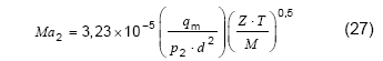
Equation [23] & [24] and [25] & [26] in API RP 521, 1997 (previous revision) are used to calculate the Mach number and Critical pressure of gas in the pipe.
Mach number
In imperial unit,
In metric unit,
Critical pressure
In imperial unit,
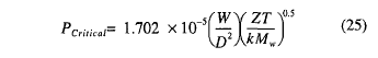
In metric unit,

After the API RP 521 is updated, similar equations used to calculate Mach number and Critical pressure has minimum modification.
Mach number
In imperial unit,
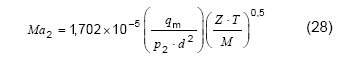
In metric unit,
Critical pressure
In imperial unit,
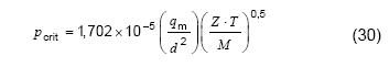
In metric unit,
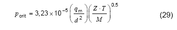
Detail review on above equations, the specific heat capacity ratio (k) has been removed from the original equation. Is this a correction or an error ?
- API R 521 1993 – No specific heat capacity ratio (k) included in the equation. However, API has included the k factor into the equation when it revised to API RP 1997. Once again, when it revised recently to 2007, the k factor has been removed again.
- Quick derivation showed that k factor should appear in the equation.
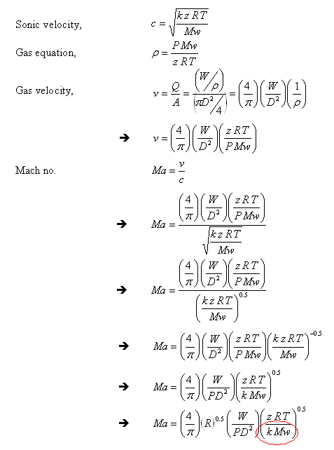
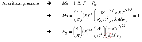
Based on simple derivation works, it ended-up with inclusion of k factor in the equation.
This discrepancy has been highlighted to API committee manager attention and quick response indicated equations in current edition (2007) are correct where k factor should not appear in those equations. Due to manning issue, no detail basis disclosed. Details searching do not find any supporting documents.
k factor generally range from 1.09 to 1.41 for most gases. Inverse square-root of k would range from0.84 to 0.96. Inclusion of k in the equation would probably bring down Mach number and critical pressure. Both impacts are partially balancing each and minimum impact to flowrate.
After further discussion and anaylsis, it's found that considering isothermal flow, the k factor should be omitted from the Mach number and critical pressure calculation. Details derivation may refer to "Removal of Specific Heat ratio (k) in the Mach No. & Critical Pressure Calculation".
Updated
- Nov 8, 2007 : This issue is being discussed in CheResource forum (Click HERE to view)
- Sept 28, 2008 : Post updated with omission of k factor.
Further Reading :
- Removal of Specific Heat ratio (k) in the Mach No. & Critical Pressure Calculation
- Controlled and Non-controlled Type Depressuring.
- How to apply valve equation in HYSYS Depressuring ?
- 12 Features required for Shutdown Valve (SDV)
- ERRATA - API Std 521, Pressure Relieving and Depressuring Systems
- Requirement of overpressure protection devices on system design to PIPING code
Labels: Depressurization, Loss Prevention, Overpressure Protection, Pressure Relief Device, Safety
Tuesday, November 6, 2007
In earlier post "How to apply valve equation in HYSYS Depressuring ?"
Non-controlled Type Depressuring
Non-controlled type is the most ordinary type of depressuring arrangement. Generally it consists of a Blowdown Valve (BDV) for isolation purpose with a correctly sized restriction orifice (RO) to limit peak depressuring rate.

Non-controlled type depressuring is commonly apply throughout plant depressuring system. It can depressure the system from initial pressure (Pi) to final pressure (Pf) within required time frame (i.e. 15 minutes). As it is a fixed bore restriction orifice, the initial depressuring rate is high and gradually decrease to minimum depressuring rate at the final condition.
This arrangement is conventional, simple and reliable for most depressuring system without any process or equipment limitation.
To model this type of depressuring in HYSYS rather simple, i would always propose to use the [General] vapor flow equation for critical flow case and [Subsonic] vapor flow equation for subcritical case.
Controlled Type Depressuring
For some systems such as compressor and mole sieve bed, the depressuring rate needs to be controlled in order to avoid damage of compressor seal and mole sieve bed. This requirement generally imposed by the equipment supplier to the client and they generally limit the rate of pressure drop e.g 20 bar / min for compressor seal, 50 psi/ min for mole sieve bed, etc. With this additional requirement, an ordinary non-controlled type depressuring (single BDV+RO) may not meet both requirements. It could either meeting the 15 minutes depressuring time but with high rate of pressure drop during initial depressuring or meeting the rate of pressure drop but with extended depressuring time (>15 minutes). A controlled type depressuring method is required.
First type would be multiple BDV with RO (smaller). See below image.

The idea is to provide small opening for depressuring during initial depressuring, as the system pressure is reduced, the opening for depressuring is gradually rise to increase the depressuring rate. Opening of BDVs will be staggered according to time in order to limit the rate of pressure drop whilst depressuring the system pressure within the required time (i.e. 15 minutes). The method is step change of opening and depressuring rate will change from time to time but within a flow rate band.
Second type would be a flow control valve with a flow control loop. See below image.
To model the first type of controlled depressuring using multiple BDV & RO in HYSYS is rather complicated. Presently (version 2006) there is no multiple depressuring unit is available in HYSYS. I would propose to conduct series of batch depressuring (similar to single BDV+RO case) with different orifice size.
To model the second type of controlled depressuring using FCV, it is proposed to use the vapor flow equation of [Fisher] and [Masoneilan] may be applied. This involve trial-and-error to find a suitable control valve module to facilitate the depressuring rate.
Further Reading :
- How to apply valve equation in HYSYS Depressuring ?
- 6 elements & factors lead to high quality question
- Carefully assess information in the web
- 12 Features required for Shutdown Valve (SDV)
- ERRATA - API Std 521, Pressure Relieving and Depressuring Systems
- Requirement of overpressure protection devices on system design to PIPING code
Labels: Depressurization, Emergency Shutdown, HYSYS
Thursday, October 25, 2007
Depressurization study is one of the mandatory studies in oil and gas for long time. Thus process simulator common used in oil & gas such as HYSYS, PRO-VISION, etc have built-in depressuring module which specifically sued for depressurization study. HYSYS has been in the market for more than 15 years and it is well accepted by many users as it commonly known with its “real time” information and user friendly interface. One of section within the depressuring unit where user needs to provide information is the depressuring valve parameter page. The valve parameter page is basically to define the characteristic and vapor flow equation of depressuring device. Users are free to choose those seven (6) vapor flow equations (built-in), There are :
- Fisher
- Masoneilan
- Relief valve
- Supersonic
- Subsonic
- General
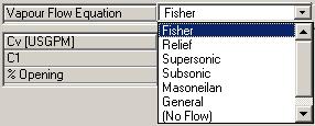
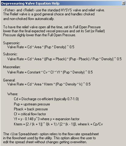
HYSYS recommends to used [Fisher]
In my point of view,
For non-controlled depressuring system, other equations such as
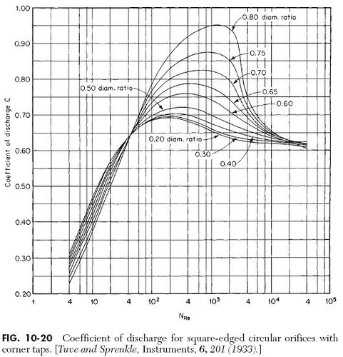
Generally the Reynolds number at the orifice throat is higher than 10,000, thus the Discharge coefficient is in the range of 0.6 to 0.65. Beware that HYSYS has recommended the used of 0.7 to 1.0. This may be true when the Reynolds number is in the range of 100 to 10,000. User shall always check at the end of study. Personally I would recommend to us 0.6 and reconfirm with Reynolds Number check by end of run. One shall remember this
You comments and advices are welcome.
Further Reading :
Labels: Depressurization, Emergency Shutdown, HYSYS
