Tuesday, November 6, 2007
Oil and gas facilities is generally required to be depressured to a safe level within a reasonable time during emergency situation. The requirements are clearly stated in the API Std 521 2007 edition, section 5.20.1.
In earlier post "How to apply valve equation in HYSYS Depressuring ?"
In earlier post "How to apply valve equation in HYSYS Depressuring ?"
where i have discussed what, where and how to apply vapor flow equations in the HYSYS Depressuring valve parameter page. In that posts, i have mentioned about controlled and non-controlled type depressuring but without detailing them. In this i will elaborate a bit more the function and application of controlled and non-controlled type depressuring.
Non-controlled Type Depressuring
Non-controlled type is the most ordinary type of depressuring arrangement. Generally it consists of a Blowdown Valve (BDV) for isolation purpose with a correctly sized restriction orifice (RO) to limit peak depressuring rate.

Non-controlled type depressuring is commonly apply throughout plant depressuring system. It can depressure the system from initial pressure (Pi) to final pressure (Pf) within required time frame (i.e. 15 minutes). As it is a fixed bore restriction orifice, the initial depressuring rate is high and gradually decrease to minimum depressuring rate at the final condition.
This arrangement is conventional, simple and reliable for most depressuring system without any process or equipment limitation.
To model this type of depressuring in HYSYS rather simple, i would always propose to use the [General] vapor flow equation for critical flow case and [Subsonic] vapor flow equation for subcritical case.
Controlled Type Depressuring
For some systems such as compressor and mole sieve bed, the depressuring rate needs to be controlled in order to avoid damage of compressor seal and mole sieve bed. This requirement generally imposed by the equipment supplier to the client and they generally limit the rate of pressure drop e.g 20 bar / min for compressor seal, 50 psi/ min for mole sieve bed, etc. With this additional requirement, an ordinary non-controlled type depressuring (single BDV+RO) may not meet both requirements. It could either meeting the 15 minutes depressuring time but with high rate of pressure drop during initial depressuring or meeting the rate of pressure drop but with extended depressuring time (>15 minutes). A controlled type depressuring method is required.
First type would be multiple BDV with RO (smaller). See below image.

The idea is to provide small opening for depressuring during initial depressuring, as the system pressure is reduced, the opening for depressuring is gradually rise to increase the depressuring rate. Opening of BDVs will be staggered according to time in order to limit the rate of pressure drop whilst depressuring the system pressure within the required time (i.e. 15 minutes). The method is step change of opening and depressuring rate will change from time to time but within a flow rate band.
Second type would be a flow control valve with a flow control loop. See below image.
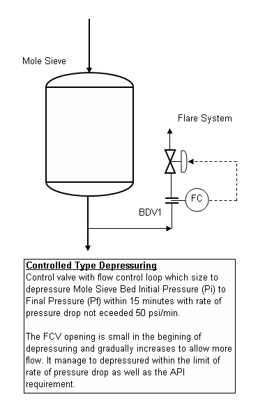
It basically to maintain a constant depressuring rate by varying the valve opening. It can limit the rate of pressure drop whilst depressuring the system pressure within the required time (i.e. 15 minutes). It can maintain a rather constant flow throughout the entire depressuring period, however reliability could be a major issue in most application.
To model the first type of controlled depressuring using multiple BDV & RO in HYSYS is rather complicated. Presently (version 2006) there is no multiple depressuring unit is available in HYSYS. I would propose to conduct series of batch depressuring (similar to single BDV+RO case) with different orifice size.
To model the second type of controlled depressuring using FCV, it is proposed to use the vapor flow equation of [Fisher] and [Masoneilan] may be applied. This involve trial-and-error to find a suitable control valve module to facilitate the depressuring rate.
Further Reading :
Non-controlled Type Depressuring
Non-controlled type is the most ordinary type of depressuring arrangement. Generally it consists of a Blowdown Valve (BDV) for isolation purpose with a correctly sized restriction orifice (RO) to limit peak depressuring rate.
Non-controlled type depressuring is commonly apply throughout plant depressuring system. It can depressure the system from initial pressure (Pi) to final pressure (Pf) within required time frame (i.e. 15 minutes). As it is a fixed bore restriction orifice, the initial depressuring rate is high and gradually decrease to minimum depressuring rate at the final condition.
This arrangement is conventional, simple and reliable for most depressuring system without any process or equipment limitation.
To model this type of depressuring in HYSYS rather simple, i would always propose to use the [General] vapor flow equation for critical flow case and [Subsonic] vapor flow equation for subcritical case.
Controlled Type Depressuring
For some systems such as compressor and mole sieve bed, the depressuring rate needs to be controlled in order to avoid damage of compressor seal and mole sieve bed. This requirement generally imposed by the equipment supplier to the client and they generally limit the rate of pressure drop e.g 20 bar / min for compressor seal, 50 psi/ min for mole sieve bed, etc. With this additional requirement, an ordinary non-controlled type depressuring (single BDV+RO) may not meet both requirements. It could either meeting the 15 minutes depressuring time but with high rate of pressure drop during initial depressuring or meeting the rate of pressure drop but with extended depressuring time (>15 minutes). A controlled type depressuring method is required.
First type would be multiple BDV with RO (smaller). See below image.
The idea is to provide small opening for depressuring during initial depressuring, as the system pressure is reduced, the opening for depressuring is gradually rise to increase the depressuring rate. Opening of BDVs will be staggered according to time in order to limit the rate of pressure drop whilst depressuring the system pressure within the required time (i.e. 15 minutes). The method is step change of opening and depressuring rate will change from time to time but within a flow rate band.
Second type would be a flow control valve with a flow control loop. See below image.
To model the first type of controlled depressuring using multiple BDV & RO in HYSYS is rather complicated. Presently (version 2006) there is no multiple depressuring unit is available in HYSYS. I would propose to conduct series of batch depressuring (similar to single BDV+RO case) with different orifice size.
To model the second type of controlled depressuring using FCV, it is proposed to use the vapor flow equation of [Fisher] and [Masoneilan] may be applied. This involve trial-and-error to find a suitable control valve module to facilitate the depressuring rate.
Further Reading :
- How to apply valve equation in HYSYS Depressuring ?
- 6 elements & factors lead to high quality question
- Carefully assess information in the web
- 12 Features required for Shutdown Valve (SDV)
- ERRATA - API Std 521, Pressure Relieving and Depressuring Systems
- Requirement of overpressure protection devices on system design to PIPING code
Labels: Depressurization, Emergency Shutdown, HYSYS
posted by Webworm, 3:45 AM


0 Comments:
Post a Comment
Let us know your opinion !!! You can use some HTML tags, such as <b>, <i>, <a>
Subscribe to Post Comments [Atom]
Home:
<< Home