Tuesday, September 16, 2008
Display problem ? Click HERE
If you have worked on P&ID, you probably have seen an isolation valve with a globe valve across a pressure relief valve (PRV). See below image.
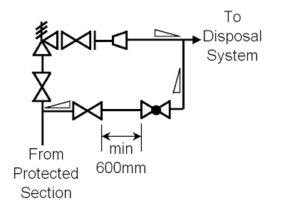
What is this arrangement and what the purpose of installing them ?
Recommended :
- Subscribe FREE - Chemical Engineering
- Tips on Succession in FREE Subscription

Many engineer may have aware of this purpose of this line. This arrangement is a manual blowdown line. It is normally used system inerting during start-up and system purging during shutdown maintenance. As the source of the inventory is same as PRV i.e. vessel and the discharge location is same i.e. flare, thus it is generally drawn in P&ID as such. Similarly it also being arranged in parallel with PRV in actual installation.
Some engineers may understand the main purpose of this arrangement but somehow mis-called it as PRV bypass. It is pretty same as the control valve (CV) bypass arrangement. In reality operator can operate the CV bypass and throttle the flow manually by the bypass globe valve while operator take out the control valve for maintenance purpose. However, operator is absolute not allowed to bypass the PRV. When designer write the operating manual, the correct terms shall be used to avoid any misunderstanding. This could be a minor error however sometime it is important.
Some recommended features associate with this arrangement are as follow :
Although above manual blowdown line is pretty simple, there are still features associate with it. Above is non-exhaustive list of features. If you find any special conditions, welcome your advice and comments.
Related Post
- Subscribe FREE - Chemical Engineering
- Tips on Succession in FREE Subscription
Many engineer may have aware of this purpose of this line. This arrangement is a manual blowdown line. It is normally used system inerting during start-up and system purging during shutdown maintenance. As the source of the inventory is same as PRV i.e. vessel and the discharge location is same i.e. flare, thus it is generally drawn in P&ID as such. Similarly it also being arranged in parallel with PRV in actual installation.
Some engineers may understand the main purpose of this arrangement but somehow mis-called it as PRV bypass. It is pretty same as the control valve (CV) bypass arrangement. In reality operator can operate the CV bypass and throttle the flow manually by the bypass globe valve while operator take out the control valve for maintenance purpose. However, operator is absolute not allowed to bypass the PRV. When designer write the operating manual, the correct terms shall be used to avoid any misunderstanding. This could be a minor error however sometime it is important.
Some recommended features associate with this arrangement are as follow :
- The isolation valve and globe valve shall be arranged such that no low pocket present as liquid possible present in low pocket promote corrosion
- These arrangement install at high point so that liquid is sloping away from them
- Maintain a distance i.e. 600mm between isolation valve and globe valve to avoid isolation valve stuck open during manual blowdown. See reasoning in "Why Restriction Orifice is some distance from Blowdown valve ?"
- The recommended size of the line and valve is 2". If size smaller then 2" is used, concern of severe vibration of small bore connection (SBC) shall be addressed.
- The short line downstream of globe valve to connection is recommended to design to MACH number lower than unity (1) i.e. 0.8 when the globe valve is fully open. This is to avoid operator inadvertently open the globe valve.
- The downstream piping shall be sufficiently thick to ensure it is failed on acoustically induced vibration.
- The isolation valve may be Normally Closed (NC). However, losing inventory due to inadvertently open of this blowdown valve is deem to be a concern, the isolation valve may be Car Sealed Close (CSC) or Locked Close (LC).
- Prior to any blowdown, the operator may leave the upstream system settle out. This allow the internal fluid temperature cooled to minimum possible ambient temperature. Manual blowdown after settled out would lead to very low temperature downstream of globe valve. Thus the low temperature during manual blowdown shall be studied to ensure the material will not failed on low temperature embrittlement.
- If the fluid is having high pour point, solidify or crystallize under minimum ambient temperature, etc, may consider insulating and/or heat trace the line.
Although above manual blowdown line is pretty simple, there are still features associate with it. Above is non-exhaustive list of features. If you find any special conditions, welcome your advice and comments.
Related Post
- A refresh to Process Engineer on few phenomenons in restriction orifice
- Bug in ASPENTECH HYSYS 2006 Dynamic Depressuring Fisher Valve model
- Controlled and Non-controlled Type Depressuring
- How to apply valve equation in HYSYS Depressuring ?
- Why Restriction Orifice is some distance from Blowdown valve ?
- Restrcition Orifice Used in Many Applications in Different Manners
- How to Resolve Issue with PSV Inlet Line Loss Exceeded 3% of Set pressure
- Few Concerns & Recommendations of PSV Discharge Tail pipe
- Few Concerns & Recommendations on PSV INLET line
Labels: Depressurization, Overpressure Protection, Pressure Relief Device
posted by Webworm, 2:52 PM


0 Comments:
Post a Comment
Let us know your opinion !!! You can use some HTML tags, such as <b>, <i>, <a>
Subscribe to Post Comments [Atom]
Home:
<< Home