Friday, September 12, 2008
Display problem ? Click HERE
Recommended :
- Tips on Succession in FREE Subscription
- Subscribe FREE - Hydrocarbon Engineering
 Isothermal flow equation is widely used to size Pressure Relief Valve (PRV) discharge piping and flare network all the way to flare tip. Generally sizing of PRV discharge or flare network piping can usually be simplified by starting at the system outlet i.e. flare tip, where the pressure i.e ATMOSPHERE is known , and working backward through the network till the PRV. The back pressure can affect performance of PRV as discussed in "Several Impact of Backpressure on Conventional PRV" and "How Back Pressure Affect Conventional PSV Set Pressure Subject to It Vent". From the outlet system, the calculations are performed in a stepwise manner for each pipe segment of constant diameter, backward through the network.
The isothermal flow equation based on inlet and outlet Mach number are as given in Equation (25) and (26) in API Std 521 - ISO 23251, Edition 5, Jan 2007, "Pressure-relieving and Depressuring Systems - Addendum-May2008". Figure 14 (see below) in this standard is a typical graphical representation of Equation (25) and it may be used to calculate the inlet pressure, p1, for a line segment of constant diameter where the outlet pressure is known.
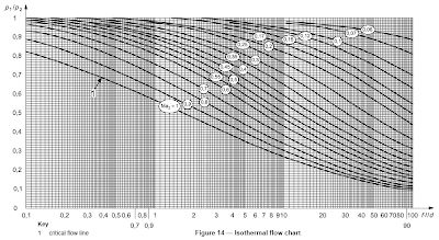
The vertical axis represented by (P1/P2) while the horizontal axis represented (f.l/d). From the definition, P1 is inlet absolute pressure while P2 is outlet absolute pressure. As P1 shall always larger than P2, thus P1/P2 shall always more than unity (1). However, looking at the vertical (P1/P2) axis, the value is from zero to one. This seen un-realistic.
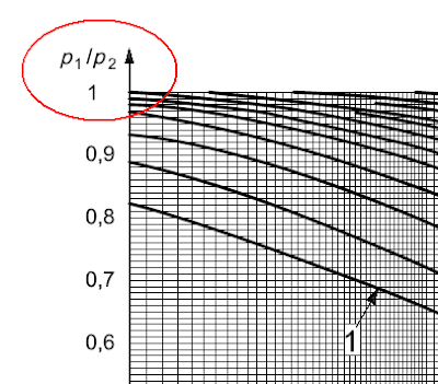
A back check on the previous revision (1997) and source paper, it was found that the vertical axis should be (P2/P1) instead of (P1/P2). The minor error will be reflected to API for verification.
Thanks to Sheiko to share this information with Chemical Process Technology.
- Tips on Succession in FREE Subscription
- Subscribe FREE - Hydrocarbon Engineering
Isothermal flow equation is widely used to size Pressure Relief Valve (PRV) discharge piping and flare network all the way to flare tip. Generally sizing of PRV discharge or flare network piping can usually be simplified by starting at the system outlet i.e. flare tip, where the pressure i.e ATMOSPHERE is known , and working backward through the network till the PRV. The back pressure can affect performance of PRV as discussed in "Several Impact of Backpressure on Conventional PRV" and "How Back Pressure Affect Conventional PSV Set Pressure Subject to It Vent". From the outlet system, the calculations are performed in a stepwise manner for each pipe segment of constant diameter, backward through the network.The isothermal flow equation based on inlet and outlet Mach number are as given in Equation (25) and (26) in API Std 521 - ISO 23251, Edition 5, Jan 2007, "Pressure-relieving and Depressuring Systems - Addendum-May2008". Figure 14 (see below) in this standard is a typical graphical representation of Equation (25) and it may be used to calculate the inlet pressure, p1, for a line segment of constant diameter where the outlet pressure is known.
The vertical axis represented by (P1/P2) while the horizontal axis represented (f.l/d). From the definition, P1 is inlet absolute pressure while P2 is outlet absolute pressure. As P1 shall always larger than P2, thus P1/P2 shall always more than unity (1). However, looking at the vertical (P1/P2) axis, the value is from zero to one. This seen un-realistic.
A back check on the previous revision (1997) and source paper, it was found that the vertical axis should be (P2/P1) instead of (P1/P2). The minor error will be reflected to API for verification.
Thanks to Sheiko to share this information with Chemical Process Technology.
Related Topics
Labels: Overpressure Protection, Pressure Relief Device
posted by Webworm, 2:29 PM


0 Comments:
Post a Comment
Let us know your opinion !!! You can use some HTML tags, such as <b>, <i>, <a>
Subscribe to Post Comments [Atom]
Home:
<< Home