Thursday, December 15, 2011
Earlier post "Mal-Distribution of Phases at T-Junction Phenomenon" and "Stagnant Liquid In Inclined Parallel Pipe Downstream of T-Junction" have shown two phase flow mal-distribution and stagnant liquid phenomenon at T-junction or splitting tee.
The flow distribution from a manifold to parallel channels is becoming of interest in predicting the heat transfer performance of heat exchangers. As discussed, due to maldistribution of two phase flow at T-junction, flow rates through the channels to each heat exchanger are not uniform. In the extreme case, there is almost no flow through some of them (i.e. stagnant liquid phenomenon). As of today, there is still no general way to predict the distribution of two-phase mixtures at header–channel junctions (T-junction).
Simulation studies by Bernoux et al. (2001) with two-phase distribution at the inlet manifold of compact heat exchangers, results showed that the vapor distribution to the channels became uniform with the increase of the mass quality (Xv), but the liquid distribution still remained unbalanced. Besides, the liquid distribution through the channels was not much sensitive to the mass flux (MFlux).
Flow behavior studies (by Osakabe et al, 1999) in a horizontal square header (with each side being 40 mm) connected to four parallel vertical tubes (10 mm in diameter) for the bubbly and slug flows at the inlet, largest amount of the liquid flow into the first tube for a low mass quality (Xv) flow in the header; however, the tendency of mal-distribution is reduced with the increase of the mass quality (Xv) inside the header.
Flow behavior at one junction has no influence on that at the next junction. On the other hand, for the most of the compact heat exchangers, the distance between the channels is comparable to or even smaller than the header size (hydraulic diameter), flow interaction between the junctions has to be taken into account.
Infact, behavior of flow separation in small T-junctions appeared different from that in the large T-junctions. There are strong interaction between each T-junctions. The flow behavior at one T-junction is strongly influenced by other T-junction especially when the distance between the T-junction is equivalent to or smaller than the hydraulic diameter of the header (as reported by Lee & Lee, 2004).

Further investigation on two-phase flow behavior at the upward header co-current flow and horizontal rectangular parallel channels and simulating the corresponding parts of compact heat exchangers shown that intrusion depth of the channels into header affects flow distribution of the liquid-phase. Less amount of liquid was separated out through the channels at the rear part except near the end-partition with the zero intrusion depth, Reversed trend observed for deeper intrusion. This indicated that a uniform distribution could be obtained by adjusting the intrusion depth. Deeper intrusion channel promote mixing effect and hence the uniform distribution to each outlet.
Above shown that mal-distribution of two phase flow at T-junctions affects by many factors i.e. vapor mass quality, flow pattern, distance of T-junction, size of T-junction and header size, penetration of T-junction into header, etc. Infact, above only several factors affecting mal-distribution, there are many more factors affecting it. In a compact heat exchanger i.e. Plate Fin Heat Exchanger (PFHE), Brazed Aluminum Heat Exchanger (BAHX), gas & liquid fraction flow from header to each channel may be different from tube to tube. This could seriously affects the heat transfer performance of the heat exchanger. Not only that performance varies at each channel would lead to change in temperature profile, and hence thermal stress profile of heat exchanger which increase the fatigue cracking tendency and life span of the heat exchanger.
Related Topics
- Stagnant Liquid In Inclined Parallel Pipe Downstream of T-Junction
- Mal-Distribution of Phases at T-Junction Phenomenon
- Problems Caused by Two Phase Gas-Liquid Flow
- Slugging & Slugcatcher
- Liquid Slug Stabiliser - Another type of slugcatcher
- Assess Potential Piping Failure Due to Valve Quick Opening with Two-Phase Vapor Liquid
- How Fluid Characteristic affect 2 phase Relief via PSV on Liquid filled Vessel Exposing to External Fire
Labels: Fluid Flow, Oil and Gas
Wednesday, December 14, 2011
In earlier post "Mal-Distribution of Phases at T-Junction Phenomenon", there were several mal-distribution phenomenon shown. In this post there is another phenomenon where engineer may not see or feel it and it may not has any consequence. It is flow preferential and stagnant liquid phenomenon in a inclined splitting tee.

Taitel et al (1999 & 2003) has investigated two phase flow with common inlet, split at impacting T-junction, flow in inclined parallel pipes and merge at common outlet. Flow splitting of gas and liquid in four (4) parallel pips was investigated. Experimental results were obtained for 0°, 5°, 10° and 15° inclinations.
For the horizontal case (0°) the flow takes place in all of the 4 pipes, usually with an "approximately" even splitting. For the inclined pipes various flow configuration could take place. For low liquid and gas flow rates the two-phase mixture prefers to flow in a single pipe while stagnant liquid fills part of the other three (3) pipes. As the flow rates of liquid and gas increase, flow in two, three and eventually in four pipes takes place.
For the horizontal case (0°) the flow takes place in all of the 4 pipes, usually with an "approximately" even splitting. For the inclined pipes various flow configuration could take place. For low liquid and gas flow rates the two-phase mixture prefers to flow in a single pipe while stagnant liquid fills part of the other three (3) pipes. As the flow rates of liquid and gas increase, flow in two, three and eventually in four pipes takes place.
This has provided some insight and idea to the designer and operator, there is a minimum flow for two phase flow in parallel pipes. Under turndown operation, there is possible flow in single pipe while liquid column stagnant in the other pipe. Whenever increase production, it shall be gradually increase to avoid large liquid volume feed to the downstream equipment and pipe failure due to slugging flow in downstream pipe.
Another potential issue is present of heavy sand in the two phase flow. Heavy sand will tend to stays and accumulates in the stagnant liquid and potentially partially block the pipes. Therefore, this stagnant liquid phenomenon should be checked and taken care during design and operation phase.
- Mal-Distribution of Phases at T-Junction Phenomenon
- Problems Caused by Two Phase Gas-Liquid Flow
- Slugging & Slugcatcher
- Liquid Slug Stabiliser - Another type of slugcatcher
- Assess Potential Piping Failure Due to Valve Quick Opening with Two-Phase Vapor Liquid
- How Fluid Characteristic affect 2 phase Relief via PSV on Liquid filled Vessel Exposing to External Fire
- Facts about Erosion & Erosion-Corrosion
Labels: Fluid Flow, Oil and Gas
Monday, December 12, 2011
Multiphase flow, primarily gas-liquid flow, exists in chemical, power, oil/gas production and refining plants. Multiphase flow is very complex phenomena. Most application has considered that fluid split at T-junction, all phases will be evenly split between the run and branch. In reality, maldistribution of phase occurred at T-junction. Each phase has their preference route. This maldistribution phenomenon has been experienced in many industrial applications.
Mal-Distribution of Phases at T-Junction Phenomenon
In the Oil and gas, refinery, petrochemical and chemical plant, pipes has been widely used to transfer product from equipment to equipment for further processing. Starting from offshore platform, oil & gas produce from reservoir via wellheads, partially stabilized in production separators (sometime produced water knocked-out in the production separator and further re-inject back to reservoir or treated and disposed locally), separated gas and condensate/oil will be transport to onshore via separate long pipelines. Along the pipeline, external cooling by ambient and seawater couple with pressure drop in the pipeline, condensation will occur in some places in the pipeline and two phase flow initiated. Gas with condensate arrived onshore will be dumped into a multi-fingers slugcatcher. Impacting Tee will be used to split the flow between the fingers. Gas-condensate is then separated in the slugcatcher via slight-inclined horizontal pipe with vertical Tee. At the impacting Tee, maldistribution of gas & condensate between the branches are observed in reality. These ended-up some fingers are over capacity and some under capacity.
Production from several wellhead platforms will be send to central processing platform (CEP) for partial separation and stabilization via long subsea pipeline. Due to geographical arrangement of wellhead platforms and well develop at different phases, those pipelines could be mixed at topside or subsea using Tee.
Gaslift used to enhance oil productivity will be supplied from central processing platform via long gaslift pipeline. The gaslift pipeline will be delivered from one platform to another platform. Tee will be used to split the gas flow. In order to avoid condensation, generally the gaslift dew point will be depressed to avoid condensation along the gaslift pipeline. Inefficient performance and mal-operation of topside gaslift dew point control will result saturated gas feed into the gaslift pipeline. Similar to above gas pipeline, condensation occurred in the long pipeline due to external cooling and pressure drop and affect the proper split.
| Featured Resources: | |
 | LNG Industry Provides global coverage of the entire LNG value chain.... >> |
Oil production system producing high viscosity oil, steam will be injected to enhance oil recovery. Multiple steam injection is implemented to ensure proper distribution of steam and increase the oil recovery efficiency. Steam supply from main header will be distributed to all injection points via tees. In some cases, steam is supplied from central utility production unit which is far away from the users, cooling by external (imperfect insulation) and pressure drop along header will lead to two phase flow. Maldistribution of steam-condensate at each split will result oil recovery performance dropped.
The LPG or natural gas will be supplied to users such as factory, household, etc. A lot of pipeline and tees will be used for transfer and splitting the flow. Similar to above gas pipeline, condensation could occur in the pipeline and distribution network, malditribution at the splitting tee and could result some users received large amount of condensate.
In the chemical plant, there are two phase flow gas (with low liquid loading) feeding to condenser. In order to increase operability and turndown, multiple condensers will be installed. When the plant is operate under partial capacity, some condensers will be put in operation. Maldistribution occurred at splitting tee result some condenser over capacity (fed with high liquid loading) and the some condenser under capacity (fed with low liquid loading).
Phase maldistribution has been reported from offshore platforms in the UK North Sea. Two main (phase) vessel separators has been installed in parallel in order to enable production to continue albeit at a reduced level if there was a need for maintenance or modification of a separator. To ensure an even split of the phases, an impacting T-junction was employed. When the system was started up it was found that one separator received most of the gas whilst the other got most of the liquid. Inspection of the pipework upstream of the junction showed that bend located upstream result centrifuging of the phases and presenting each outlet with substantially one phase
There are others phase maldistribution observed on T-junction. For example, phase separation in main coolant piping of light water nuclear reactor (LWR) can play significant role in the effectiveness of emergency core cooling (ECC) system during analysis of Loss-of-coolant-accident (LOCA).
Therefore, in handling vapor near condensation point or two phase flow, phase separation is one of the phenomenon shall be analyzed to minimize mal-distribution.
Related Topics
Related Topics
- Problems Caused by Two Phase Gas-Liquid Flow
- Assess Potential Piping Failure Due to Valve Quick Opening with Two-Phase Vapor Liquid
- How Fluid Characteristic affect 2 phase Relief via PSV on Liquid filled Vessel Exposing to External Fire
- Facts about Erosion & Erosion-Corrosion
- Erosion & Erosion - Corrosion
- Several Criteria and Constraints for Flare Network - Process
Labels: Fluid Flow, Oil and Gas
Tuesday, March 2, 2010
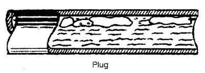
Two phase gas liquid flow is commonly occur in any oil & gas production and processing system. Several flow patterns can occur in two phase gas liquid flow. There are Bubble flow (with minimum vapor bubble), Plug flow, Stratified flow, Wavy flow, Slug flow, Annular flow and Mist/Dispersed flow (with minimum liquid droplet). Previous post "Problems Caused by Two Phase Gas-Liquid Flow" has discussed about obvious and non-obvious location where two phase gas liquid can present. Problem caused by two phase gas liquid flow such as Impingement erosion, Splashing erosion, Cavitation erosion, Flashing erosion, Flow induced vibration, Surge / hammer, Noise, Decrease process performance and Phase separation possibly lead to severe consequence. Minimizing / prevention of two phase gas liquid becoming important during design phase.
As discussed in "Some Measures To Prevent Problem Caused by Two Phase Gas Liquid Flow", the destructive level of two phase gas liquid flow varies with flow pattern. One shall try to design their system to avoid Slugging flow and/or plugging as slugging/plugging can lead severe vibration and erosion. The destructive level reduce from slugging flow to stratified flow, and minimum at annular, mist and bubble flow. So a process engineer shall design their system to move away from slugging flow.

Slugging flow in Horizontal pipe
Slugging flow can occur in horizontal pipe and vertical pipe. However, the flow pattern may be slightly difference. You may view slugging flow in horizontal pipe in below video clip.
Slugging flow in horizontal pipe
For slugging flow in horizontal pipe, trapped vapor is main stay at the top of pipe, flowing at high velocity pushing liquid slug move forward. Liquid slug right in front of trapped vapor is accelerated by the vapor flow. As slug velocity is increased and couple with gravity force acting on the slug, liquid slug becomes unstable. Liquid slug will destroy and liquid slug is dropped to bottom of pipe.Trapped vapor at the back of liquid slug loss resistance (due to liquid slug) is accelerated at high velocity. As the vapor is moving at high velocity where it is exceeded the inception velocity, liquid at the bottom of pipe is moving upward to the top of pipe, close the vapor gap and form another liquid slug. This process of slug formation, accelerates by vapor flow and slug destroy due to gravity force and weak surface tension will repeat continuously. The repeated cycle will generate severe vibration, noise and erosion to the pipe.

Below is a video clip for slugging flow in vertical upward pipe.
Slugging flow in Vertical upward pipe
Slugging flow in Vertical upward pipe
The vapor is trapped in the liquid flow and flow upward together. Large trapped vapor is sometime called Taylor bubbles flowing upward and liquid is separating Taylor bubbles. Between two Taylor bubbles, smaller bubbles are following upward as well. These bubble is rather unstable. They may coalesce to form larger bubble and join the large Taylor bubble or they may destroy due to liquid movement. As the Taylor bubble moving upward, liquid is moving at lower speed between Taylor bubble and pipe wall will tends to entrain vapor to form smaller bubble.
Related Post
- Some Measures To Prevent Problem Caused by Two Phase Gas Liquid Flow
- Problems Caused by Two Phase Gas-Liquid Flow
- Assess Potential Piping Failure Due to Valve Quick Opening with Two-Phase Vapor Liquid
- How Fluid Characteristic affect 2 phase Relief via PSV on Liquid filled Vessel Exposing to External Fire
- Facts about Erosion & Erosion-Corrosion
- Erosion & Erosion - Corrosion
Labels: Fluid Flow, Hydraulic
Sunday, February 28, 2010
Subscribes to FREE Hydrocarbon Processing

Previous post "Problems Caused by Two Phase Gas-Liquid Flow" has discussed about obvious and non-obvious location where two phase gas liquid can present. Problem caused by two phase gas liquid flow such as Impingement erosion, Splashing erosion, Cavitation erosion, Flashing erosion, Flow induced vibration, Surge / hammer, Noise, Decrease process performance and Phase separation possibly lead to severe consequence. Minimizing / prevention of two phase gas liquid becoming important during design phase.
Prevention Principle
In minimizing / prevention of two phase gas liquid flow, one may follow below principles :
- Avoid two phase gas liquid present in process design / simulation
- Promote phase separation once two phase is present
- Avoid destructive flow pattern e.g. Slugging flow
- Proper piping arrangement
- Improvement of mechanical integrity
ELIMINATE - Avoid two phase gas liquid present in process design / simulation
Process engineer may take extra effort to avoid present of two phase gas liquid during process design. Several methods such as locate level control valve downstream of filter coalescing separator so that saturated fluid is always in liquid form before it is entering filter coalescing separator, provision of flash drum prior to flash off hydrocarbon vapor before feed the solvent to plate frame heat exchanger, provision of condensate flash drum for recovered steam condensate before it is return back to boiler, etc. These are the measures can be considered by process engineer during design phase to avoid possibility of two phase flow in the system.
Completely avoid present of two phase flow may not be possible. Saturated liquid flowing pipe, pressure drop (and ambient heating) along pipe may lead to liquid vaporization. Saturated vapor flowing in pipe, pressure drop (and ambient cooling) along pipe may results condensation. Mixing of hot saturated fluid with cool fluid can shift the equilibrium and results two phase vapor liquid flow after the mixing. Thus, avoidance of two phase gas liquid flow entirely may not be possible.Once it is present, one way is to remove of the phase from the other phase. Following measures may be considered :
Vapor flow with condensation
- Superheat vapor before it is transferred
- Provide insulation to minimize heat loss to ambient
- Provide heat tracing to compensate heat loss to ambient and avoid condensation
- Provide liquid trap along the pipe to remove liquid from vapor
- Minimize pipe length to minimize frictional loss
- Use low surface roughness material (e.g. Stainless steel) for transferring fluid
- Provision of intermediate vessel to remove liquid
Liquid flow with vaporization
- Subcooled liquid by cooling or pressurize prior to transferred
- Provide insulation to minimize heat input from ambient
- Provide vapor trap along the pipe to remove vapor from liquid
- Minimize pipe length to minimize frictional loss
- Use low surface roughness material (e.g. Stainless steel) for transferring fluid
- Provision of intermediate vessel to remove vapor
AVOIDANCE - Avoid Destructive Flow Pattern
The destructive level of two phase gas liquid flow varies with flow pattern. One shall try to design their system to avoid Slugging flow and/or plugging as slugging/plugging can lead severe vibration and erosion. The destructive level reduce from slugging flow to stratified flow, and minimum at annular, mist and bubble flow. So a process engineer shall design their system to move away from slugging flow. Proper pipe size selection and operation control may be considered to avoid destructive flow pattern.
DESIGN - Proper Piping Arrangement
Good piping arrangement may be considered to minimize the impact of two phase gas liquid flow.
- Avoid / Minimize pocketed line
- Avoid / Minimize vertical lift
- Provide low point drains / traps
- Slope away liquid from source
- Design piping to avoid liquid accumulation and promote auto-draining
STRENGTH - Improvement of mechanical integrity
Once all above measures are implemented and present of two phase gas liquid flow including slugging flow, the mechanical integrity of the piping and support system shall be improved :
- Use high and reasonable tensile strength material for piping and/or equipment
- Provision of piping support improved mechanical strength
- Increase design margin to minimize any uncertainties in design
- Conduct transient analysis and/or CFD to identify localize high stress area and strengthen weak point
Related Post
- Problems Caused by Two Phase Gas-Liquid Flow
- Assess Potential Piping Failure Due to Valve Quick Opening with Two-Phase Vapor Liquid
- How Fluid Characteristic affect 2 phase Relief via PSV on Liquid filled Vessel Exposing to External Fire
- Facts about Erosion & Erosion-Corrosion
- Erosion & Erosion - Corrosion
- Several Criteria and Constraints for Flare Network - Process
Labels: Fluid Flow, Hydraulic
Saturday, February 27, 2010
Two phase gas liquid flow is commonly occur in any oil & gas production and processing system. Several flow patterns can occur in two phase gas liquid flow. There are Bubble flow (with minimum vapor bubble), Plug flow, Stratified flow, Wavy flow, Slug flow, Annular flow and Mist/Dispersed flow (with minimum liquid droplet). See following images.


Obvious Location
Present of two phase gas liquid may be obvious and be easily identified during development phase. Typical example are Full-Well-Stream (FWS) production which possibly producing hydrocarbon in gas and liquid form. Formation water, condensed water, mercury, and injected chemical (e.g. corrosion inhibitor, hydrate inhibitor, etc) in liquid form, wax in slurry form and sand in solid form may also present in the FWS, which typically result complicated multiphase form. Partial stabilized condensate travel long distance experience high pressure drop lead to vaporization. Vapor travel long distance experience ambient and J-T (isenthalpic process) cooling lead to condensation. Hot saturated vapor is cooled by air cooler or heat exchanger results condensation, vapor or liquid passing through turbine experience isentropic process, etc. These streams are obvious and can be easily identified in process simulation. Generally example are :
Present of two phase gas liquid may be obvious and be easily identified during development phase. Typical example are Full-Well-Stream (FWS) production which possibly producing hydrocarbon in gas and liquid form. Formation water, condensed water, mercury, and injected chemical (e.g. corrosion inhibitor, hydrate inhibitor, etc) in liquid form, wax in slurry form and sand in solid form may also present in the FWS, which typically result complicated multiphase form. Partial stabilized condensate travel long distance experience high pressure drop lead to vaporization. Vapor travel long distance experience ambient and J-T (isenthalpic process) cooling lead to condensation. Hot saturated vapor is cooled by air cooler or heat exchanger results condensation, vapor or liquid passing through turbine experience isentropic process, etc. These streams are obvious and can be easily identified in process simulation. Generally example are :
- Full Well Stream (FWS)
- Partial stabilized condensate with long pipeline
- Saturated vapor with long pipeline
- Liquid stream from separator passing a level control valve
- Downstream of Air cooler / Heat exchanger
- Turbine outlet
- Hot fluid mix with cool fluid continuously
Recommended :
Subscribes to FREE Hydrocarbon Processing
Non-obvious Location
There are certain stream may be not so obvious and may not be easily identified in process simulation. Hot saturated vapor flow in long pipe experience heat loss to ambient and frictional loss, condensation begin and two phase flow (i.e. mist flow, annular flow). Cold saturated or partial subcooled liquid experience frictional loss due to fittings, piping, etc and ambient heating results vaporization and two phase flow (i.e. bubble flow, wavy flow, slugging flow). Hot stream mix with cold stream may results equilibrium change and lead to two phase. Typical area is flare collection system. Hydrocarbon in process vessel at pressure once it is drained to drain collection header may flash and lead to vaporization. Generally example are :
Subscribes to FREE Hydrocarbon Processing
Non-obvious Location There are certain stream may be not so obvious and may not be easily identified in process simulation. Hot saturated vapor flow in long pipe experience heat loss to ambient and frictional loss, condensation begin and two phase flow (i.e. mist flow, annular flow). Cold saturated or partial subcooled liquid experience frictional loss due to fittings, piping, etc and ambient heating results vaporization and two phase flow (i.e. bubble flow, wavy flow, slugging flow). Hot stream mix with cold stream may results equilibrium change and lead to two phase. Typical area is flare collection system. Hydrocarbon in process vessel at pressure once it is drained to drain collection header may flash and lead to vaporization. Generally example are :
- Saturated vapor within plant (condensation)
- Cooled or subcooled liquid within plant (vaporization)
- Flare collection
- Hydrocarbon drain collection
Problems
Two phase gas liquid flow can cause several destructive problems. There are :
- Impingement erosion
- Splashing erosion
- Cavitation erosion
- Flashing erosion
- Flow induced vibration
- Surge / hammer
- Noise
- Decrease process performance
- Phase separation
Two phase gas liquid flow can lead to impingement, cavitation & flashing erosion. Two phase gas liquid flowing fluid where heavy phase is accelerated with light phase and induced high momentum and shearing stress on surface. Slugging flow in vapor-liquid system with large slug hammering on surface induce high momentum with medium velocity and high mass flux. Mist flow with droplet accelerate at vapor velocity induce high momentum with high velocity and low mass flux. Both induce high shear stress on the surface and increase material removal rate.
Flow Induced Vibration
High velocity compressible fluid in pipe is moving in turbulence pattern. Turbulence flow will induced vibration on pipe. Once the flow induced vibration frequency meeting the natural frequency of pipe support, resonance occur can lead to severe movement of pipe support. Present of two phase gas liquid flow can generate different level of frequency and increase possibility of resonances.
Surge & Hammer
Two phase gas liquid slugging and high velocity gas moving liquid at similar speed, severe vibration can occur when liquid slug is knocking/splashing on the pipe wall, especially at bend and elbow. Hot steam mix with cold condensate at the collection header results sudden steam vapor collapse. The collapse vapor results sudden lower pressure will lead sudden replacement of surrounding condensate. Sudden movement of condensate can results significant movement of condensate as well as piping and pipe support. Under designed pipe support may fail due to severe vibration.
Quick opening of valve for incompressible, multiphase and gas/vapor will results sudden change in momentum (0 to +mv) and subsequently instantaneous peak force acting on the piping. This phenomena is commonly occurs in control valve (CV), Blowdown valve (BDV) and pressure relief device i.e. pressure relief valve (PRV) and rupture disc (RD). The instantaneous peak force acting on the piping may potentially lead to piping failure.
Noise
Above phenomenon such as Impingement, Splashing, Cavitation & Flashing Erosion, Flow Induced Vibration and Surge & Hammer may also generate noise which potentially exceeded the allowable noise limit.
Affect process performance
In oil and gas production, condensate-produced water bulk separation occur in slug catcher / inlet receiver follow by a Condensate separator. Some process design may include a filter coalescing separator to promote water droplet coalescing (using coalescing element) and separation before it is sent to Condensate stabilization. Condensate at saturation point from Condensate separator feeding to Filter Coalescing separator will experience frictional drop and potential lead to vaporization. Vapor will accumulate in the filter coalescing separator and seriously affect Coalescing activity in Filter Coalescing Separator.
Plate heat exchanger (PHE) is used in Solvent e.g. Amine, MEG, TEG, etc regeneration to recover heat from lean solvent stream and promote energy saving. Hydrocarbon and / or vapor bubble under carry from Solvent Absorber to PHE potentially accumulate in the PHE and seriously affect the heat transfer in PHE.
Phase Separation - Mal-Distribution
Air cooler used for fluid cooling is widely used in Oil & Gas and Petrochemical plant. Hot fluid is fed to a Inlet header box, distribute fluid into tubes (normally finned) where cooling take place and cooled fluid is collected in the Outlet header box. If hot two phase gas liquid fluid feeding to the inlet header box, liquid with higher momentum tends to flow preferential path (straight) compare to vapor with lower momentum. The lead to serious vapor-liquid mal-distribution. Fluid (vapor dominant) feed to tube closer to inlet possibly over cooled whilst fluid (liquid dominant) feed to tube further from inlet possibly under cooled. For large duty air cooling system, fluid may further distribute into multiple header boxes and multiple unit air cooler, this will further create mal-distribution of fluid.
Knowing the problems caused by two phase gas liquid flow, identification of potential two phase gas liquid becoming an important activity during design phase. Process engineer shall take extra care during design phase and provide necessary prevention measures to minimize / avoid occurrence of two phase flow.
Related Post
- Facts about Erosion & Erosion-Corrosion
- Erosion & Erosion - Corrosion
- Several Criteria and Constraints for Flare Network - Process
- Assess Potential Piping Failure Due to Valve Quick Opening with Two-Phase Vapor Liquid
- How Fluid Characteristic affect 2 phase Relief via PSV on Liquid filled Vessel Exposing to External Fire
Labels: Fluid Flow, hydrualic
Thursday, September 10, 2009
Display problem ? Click HERE
Recommended :
- Subscribe FREE - Chemical Engineering
- Tips on Succession in FREE Subscription

Restriction orifice (RO) is widely used to in Oil and Gas, Refinery and Petrochemical chemical plant. Simple search on internet lead you to plenty of articles related to functionality, calculation and specification of restriction orifice. "Restrcition Orifice Used in Many Applications in Different Manners" brought out a few applications of RO in the industries. Earlier post "A refresh to Process Engineer on few phenomenons in restriction orifice" has summarized a few concepts that a process engineer may needs to understand for restriction orifice :
- Subscribe FREE - Chemical Engineering
- Tips on Succession in FREE Subscription
Restriction orifice (RO) is widely used to in Oil and Gas, Refinery and Petrochemical chemical plant. Simple search on internet lead you to plenty of articles related to functionality, calculation and specification of restriction orifice. "Restrcition Orifice Used in Many Applications in Different Manners" brought out a few applications of RO in the industries. Earlier post "A refresh to Process Engineer on few phenomenons in restriction orifice" has summarized a few concepts that a process engineer may needs to understand for restriction orifice :
- Restriction orifice is used to limit flow to required or expected flowrate with the available differential pressure across.
- Vena contracta (VC) present just short distance downstream of restriction orifice
- Maximum velocity and minimum pressure at vena contracta (VC)
- Choked flow occurred when velocity at vena contracta (VC) reach sonic velocity (Ma=1). The corresponding downstream pressure (P2) at choked condition called critical pressure (Pc).
- Increase in upstream pressure (P1) will increase mass flow passing the restriction orifice but velocity at VC still maintaining at Ma=1
A young engineer asked... If compressible fluid composition and upstream pressure are fixed and choked flow already occurred, should there be other way to increase the mass flow passing the RO ?
For compressible fluid, mass flow passing through an fixed bore size RO is a function of
For compressible fluid, mass flow passing through an fixed bore size RO is a function of
- composition ( k, MW, ...)
- driving force (Differential pressure) across RO (P1-P2)
- density (function of P1, MW, z, T1)
- composition (and therefore k, MW...) remain unchanged
- reducing P2 lead to higher P1-P2 which will result higher mass flow passing RO. Mass flow increase will continue until until P2 reach critical pressure of fluid (Pc). Sonic velocity (Mach no =1) occurred at vena contrata, some distance downstream of RO. When P2 lower than Pc, further reduction of P2 will not result any mass flow increase.
- reduce upstream temperature (T1) will results higher density and higher mass flow passing RO.
Related Post
- A refresh to Process Engineer on few phenomenons in restriction orifice
- How to determine if a restriction orifice will experience cavitation ?
- Restrcition Orifice Used in Many Applications in Different Manners
- Bug in ASPENTECH HYSYS 2006 Dynamic Depressuring Fisher Valve model
- Controlled and Non-controlled Type Depressuring
- How to apply valve equation in HYSYS Depressuring ?
- Why Restriction Orifice is some distance from Blowdown valve ?
Labels: Fluid Flow, hydrualic
Wednesday, June 24, 2009
Display problem ? Click HERE
Recommended :
Subscribe FREE - Chemical Processing
 Chemical Engineering has shared a FAYF related FLUID FLOW. This FAYF is infact has been released in previous month, however, CE share with CE FREE subscriber again this month.
Fluid Type
In this FAYF, it starts with definition of fluid type such as :
i) Newtonian
ii) Power law
iii) Bingham plastic
where
Newtonian fluid
A fluid is known to be Newtonian when shear stresses associated with flow are directly proportional to the shear rate of the fluid.
Power law fluid
A structural fluid has a structure that forms in the undeformed state, but then breaks down as shear rate increases. Such a fluid exhibits “power law” behavior at intermediate shear rates
Bingham plastic fluid
A plastic is a material that exhibits a yield stress, meaning that it behaves as a solid below the stress level and as a fluid above the stress level
This one-page fact sheet summarizes information pertinent to laminar and turbulent pipe flow for the various types of fluids commonly encountered in the CPI...
Ref. :
1. Darby, R., Take the Mystery Out of Non-Newtonian Fluids, Chem. Eng., March 2001, pp. 66–73.
2. Churchil, S. W., Friction Factor Equation Spans all Fluid- Flow Regimes, Chem. Eng., November 1997, p. 91.
3. Darby, R., and Chang, H. D., A Generalized Correlation for Friction Loss in Drag-reducing Polymer Solutions, AIChE J., 30, p. 274, 1984.
4. Darby, R., and Chang, H. D., A Friction Factor Equation for Bingham Plastics, Slurries and Suspensions for all Fluid Flow Regimes, Chem. Eng., December 28, 1981, pp. 59–61.
5. Darby, R., “Fluid Mechanics for Chemical Engineers,” Vol. 2, Marcel Dekker, New York, N.Y., 2001.
Download (Only for FREE CE Subscriber)
Note :
*This FAYF is only available FREE to Chemical Engineering Magazine registered user. Login required. Subscribe FREE CE, click here.
** Download immediately as article available FREE within short period only. Do not wait.
*** Found lost link or unable to download, may contact me...
Related Topic
Labels: Fluid Flow
Friday, March 13, 2009
Recommended :
- Tips on Succession in FREE Subscription
 Condensate Pump Recirculation Valve Selection
Power plant condenser receives exhaust steam from the low pressure turbine and condenses it to liquid for reuse. Condenser back pressure range from 1.0 to 4.5 Hg absolute (3.4 to 15.2 kPa) with higher pressures possible when the cooling water temperature is elevated by using an air-cooled steam condenser. Condensate is collected in the bottom of the condenser in the hot well. The condensate feed pump supplies the subcooled water to the feedwater heaters.
- Tips on Succession in FREE Subscription
Condensate Pump Recirculation Valve SelectionPower plant condenser receives exhaust steam from the low pressure turbine and condenses it to liquid for reuse. Condenser back pressure range from 1.0 to 4.5 Hg absolute (3.4 to 15.2 kPa) with higher pressures possible when the cooling water temperature is elevated by using an air-cooled steam condenser. Condensate is collected in the bottom of the condenser in the hot well. The condensate feed pump supplies the subcooled water to the feedwater heaters.
As with most centrifugal pumps, the condensate pump is subject to overheating and cavitation if used at a flow under a minimum value recommendation by the pump manufacturer. When the flow required by the deaerator level control loop falls below this minimum recommended value, additional flow is recirculated back to the condenser by opening a valve installed in a bypass line thus maintaining the minimum flow through the pump at all time. There are problems associate with this valve and its selection. Read more...
Download
Related Topic
- Understand Boiler Efficiency
- Simple Formula To Estimate Water Viscosity
- Steam - Condensate Useful Links...
- Square-root-Square-root Formula Ease Saturated Steam-Codensate Temperature Prediction
- Useful Steam - Condensate Calculator
- Steam in FIRE...
Labels: Control valve, Fluid Flow
Monday, February 23, 2009
Display problem ? Click HERE
Recommended :
- Tips on Succession in FREE Subscription
High pressure feedwater pumps are subject to overheating and subsequently very rapid damage if used at low flow as compared to the rated capacity. The minimum flow required for pump protection is specified by the pump manufacturer. It is never less than 15% and can sometimes be 40% or more. When the flow required by the boiler is below this limit, the feedwater pump flow demand is artificially increased by discharging to the deaerator or sometimes to the condenser through a recirculation valve. The recirculation valve is required to operate either on-off within a selected range of values of flow to the boiler, or in modulating service. In this case, the flow through the control valve is equal to the difference between the pump minimum flow and the actual flow to the boiler. Modulating service avoids the waste of energy since the recirculated flow is kept at the minimum acceptable value, but it is more severe in terms of valve service.
Several precautions may have to be taken while selecting this type of recirculation valve :
Download- Tips on Succession in FREE Subscription
High pressure feedwater pumps are subject to overheating and subsequently very rapid damage if used at low flow as compared to the rated capacity. The minimum flow required for pump protection is specified by the pump manufacturer. It is never less than 15% and can sometimes be 40% or more. When the flow required by the boiler is below this limit, the feedwater pump flow demand is artificially increased by discharging to the deaerator or sometimes to the condenser through a recirculation valve. The recirculation valve is required to operate either on-off within a selected range of values of flow to the boiler, or in modulating service. In this case, the flow through the control valve is equal to the difference between the pump minimum flow and the actual flow to the boiler. Modulating service avoids the waste of energy since the recirculated flow is kept at the minimum acceptable value, but it is more severe in terms of valve service.Several precautions may have to be taken while selecting this type of recirculation valve :
- Cavitation
- Pressure drop distribution
- Axial / Radial design
- Shut-off/ Wire drawing
- Clogging
- Vibration
- Failure position
Related Topic
- Understand Boiler Efficiency
- Simple Formula To Estimate Water Viscosity
- Steam - Condensate Useful Links...
- Square-root-Square-root Formula Ease Saturated Steam-Codensate Temperature Prediction
- Useful Steam - Condensate Calculator
- Steam in FIRE...
Labels: Control valve, Fluid Flow
Monday, February 9, 2009
Display problem ? Click HERE
 Control valve capacity (Cv) for particular application is determined by the use of recognized valve sizing equations. This valve equation can be found in several handbooks i.e. Fisher, Masoneilan, etc as discussed in "Useful Documents Related to Control Valve".This article presented a simple idea why a control valve is normally operate at around 60-70% valve opening and it associated impact such as increase signal dead band effect and affect optimum controller settings-wider proportional band and faster reset. It recommended a new way to overcome the impacts by introducing VARIMAX. Read more...
Download
Related Topic
- Understand Boiler Efficiency
- Simple Formula To Estimate Water Viscosity
- Steam - Condensate Useful Links...
- Square-root-Square-root Formula Ease Saturated Steam-Codensate Temperature Prediction
- Useful Steam - Condensate Calculator
- Steam in FIRE...
Labels: Control valve, Fluid Flow
Sunday, February 1, 2009
Display problem ? Click HERE
Recommended :
- Tips on Succession in FREE Subscription
- Subscribe FREE - Processing Magazine
 In gas processing industry, gas flow has been referred to STANDARD (i.e. Sm3/hr, MMSCFD, etc) and NORMAL condition (i.e. Nm3/h). Vendor catalog in many event can be in Sm3/h or Nm3/h.
Definition
As discussed in "Avoid Confusion In "Standard" Flow Definition", definition is one of the most important factors to avoid discrepancies. First far most important task is to provide a correct definition of STANDARD and NORMAL condition. In "general",
NORMAL condition : 1.01325 bara @ 0 degC
STANDARD condition : 1.01325 bara @ 15 degC
Conversion
From this post,
Q2 = (z2/z1) x (T2/T1) x (P1/P2) x Q1 .....[1]
where
Q1 & Q2 are Volumetric Flow in m3/h for condition 1 & 2
P1 & P2 are Pressure in bar abs for condition 1 & 2
T1 & T2 are Temperature in K for condition 1 & 2
z1 & z2 are compressibility factor for condition 1 & 2
Condition 1 : 1.01325 bara @ 0 degC (NORMAL Contractor manual)
Condition 2 : 1.01325 bara @ 15 degC (STANDARD)
Assume z1 = z2 = 1
Q1 = 1 Nm3/h
From [1],
==> Q2 = (z2/z1) x (T2/T1) x (P1/P2) x Q1
==> Q2 = (288.15 / 273.15) x 1
==> Q2 = 1.055 Sm3/h
Therefore,
- Tips on Succession in FREE Subscription
- Subscribe FREE - Processing Magazine
In gas processing industry, gas flow has been referred to STANDARD (i.e. Sm3/hr, MMSCFD, etc) and NORMAL condition (i.e. Nm3/h). Vendor catalog in many event can be in Sm3/h or Nm3/h. What is the useful factor to convert Nm3/h to Sm3/h or vice versa ?
Definition
As discussed in "Avoid Confusion In "Standard" Flow Definition", definition is one of the most important factors to avoid discrepancies. First far most important task is to provide a correct definition of STANDARD and NORMAL condition. In "general",
NORMAL condition : 1.01325 bara @ 0 degC
STANDARD condition : 1.01325 bara @ 15 degC
Conversion
From this post,
Q2 = (z2/z1) x (T2/T1) x (P1/P2) x Q1 .....[1]
where
Q1 & Q2 are Volumetric Flow in m3/h for condition 1 & 2
P1 & P2 are Pressure in bar abs for condition 1 & 2
T1 & T2 are Temperature in K for condition 1 & 2
z1 & z2 are compressibility factor for condition 1 & 2
Condition 1 : 1.01325 bara @ 0 degC (NORMAL Contractor manual)
Condition 2 : 1.01325 bara @ 15 degC (STANDARD)
Assume z1 = z2 = 1
Q1 = 1 Nm3/h
From [1],
==> Q2 = (z2/z1) x (T2/T1) x (P1/P2) x Q1
==> Q2 = (288.15 / 273.15) x 1
==> Q2 = 1.055 Sm3/h
Therefore,
1 Nm3 = 1.055 Sm3
whenNORMAL condition : 1.01325 bara @ 0 degC
STANDARD condition : 1.01325 bara @ 15 degC
Related Post
- Avoid Confusion In "Standard" Flow Definition
- Relate Normal to Actual Volumtric Flow
- Air Receiver - Doubt on SCFM & CFM
- Flow Element (FE) Upstream or Downstream of Control Valve (CV) ?
- Use Ultra-Sonic Flowmeter in FLARE Gas Header for emission monitoring
- FAYF - Flowmeter selection in brief...
- Useful Documents Related to Control Valve
Labels: Fluid Flow, Unit
Friday, January 30, 2009
Display problem ? Click HERE
Recommended :
- Tips on Succession in FREE Subscription
- Subscribe FREE - Chemical Processing
A contractor engineer has sized an air receiver with 1000 Sm3/h and client engineer has rechecked the air receiver size. It was found that the basic parameters such as flowrate, operating pressure and temperature, etc are same, however air receiver size calculated by contractor engineer is different than client engineer. After several round of discussion, they found both engineers calculation method are same.
Different Defintion
A detail analysis on both calculations found that the definition of "Standard" condition are different between the contractor engineer and client engineer. Contractor engineer has used 1.01325 bara @ 0 degC (stated in contractor design manual) whilst client engineer has used 1.01325 @ 25 degC (stated in client common requirement manual). Above situation is pretty common discrepancies in design and engineering. Although both engineers talk about the same thing, "Normal" condition, the results may not be the same due the differences in definition. Thus, it is a good engineering practice to write down the defintion clearly in the calculation note or in a common design basis document.
Following are a list of "Standard" condition for several organizations :
In SI Unit :
SI & US Custom
Another factor may also cause the descrepancies is the reference unit. The defintion in SI unit may NOT same as US custom unit eventhough within an organization. For example, SPE defined Standard condition as
Conversion between two different "Normal" condition
Let take above example, 1000 Sm3/h as defined by contractor. What is the equivalent flow (Sm3/hr) for client engineer ?
Contractor manual : 1.01325 bara @ 0 degC
Client manual : 1.01325 @ 25 degC
Equation for conversion can be taken from discussion in "Relate Normal to Actual Volumtric Flow"
Q2 = (z2/z1) x (T2/T1) x (P1/P2) x Q1 .....[1]
where
Q1 & Q2 are Volumetric Flow in m3/h for condition 1 & 2
P1 & P2 are Pressure in bar abs for condition 1 & 2
T1 & T2 are Temperature in K for condition 1 & 2
z1 & z2 are compressibility factor for condition 1 & 2
Condition 1 : 1.01325 bara @ 0 degC (Contractor manual)
Condition 2 : 1.01325 bara @ 25 degC (Client manual)
Assume z1 = z2 = 1
Q1 = 1000 Nm3/h @ Condition 1
From [1],
==> Q2 = (z2/z1) x (T2/T1) x (P1/P2) x Q1
==> Q2 = (298.15 / 273.15) x 1000
==> Q2 = 1091.525 m3/h
The equivalent flow for 1000 Sm3/h @ condition 1 = 1091.525 Sm3/h @ Condition 2. Client engineer shall use 1091.525 Sm3/h in his/her calculation.
Related Post
- Tips on Succession in FREE Subscription
- Subscribe FREE - Chemical Processing
A contractor engineer has sized an air receiver with 1000 Sm3/h and client engineer has rechecked the air receiver size. It was found that the basic parameters such as flowrate, operating pressure and temperature, etc are same, however air receiver size calculated by contractor engineer is different than client engineer. After several round of discussion, they found both engineers calculation method are same.
What is the factor cause the difference ?
Different Defintion
A detail analysis on both calculations found that the definition of "Standard" condition are different between the contractor engineer and client engineer. Contractor engineer has used 1.01325 bara @ 0 degC (stated in contractor design manual) whilst client engineer has used 1.01325 @ 25 degC (stated in client common requirement manual). Above situation is pretty common discrepancies in design and engineering. Although both engineers talk about the same thing, "Normal" condition, the results may not be the same due the differences in definition. Thus, it is a good engineering practice to write down the defintion clearly in the calculation note or in a common design basis document.
Following are a list of "Standard" condition for several organizations :
In SI Unit :
- EPA - 1.01325 bara @ 25 degC
- NIST - 1.01325 bara @ 20 degC
- IUPAC - 1.0 bara @ 0 degC
- ISA - 1.01325 @ 15 degC
- SATP - 1.0 @ 25 degC
- CAGI - 1.0 bara @ 20 degC
- SPE - 1.0 bara @ 15 degC
- SHELL - 1.01325 @ 25 degC
- EXXON - 1.01325 @ 15 degC
- SPE - 14.696 psia @ 60 degF
- OSHA - 14.696 psia @ 60 degF
- OPEC - 14.73 psia @ 60 degF
- ISO 2314 - 14.696 psia @ 59 degF
- ISO 3977-2 - 14.696 psia @ 59 degF
- U.S. Army - 14.503 psia @ 59 degF
SI & US Custom
Another factor may also cause the descrepancies is the reference unit. The defintion in SI unit may NOT same as US custom unit eventhough within an organization. For example, SPE defined Standard condition as
- 1.0 bara @ 15 degC in SI unit
- 14.696 psia @ 60 degF in US custom unit
Conversion between two different "Normal" condition
Let take above example, 1000 Sm3/h as defined by contractor. What is the equivalent flow (Sm3/hr) for client engineer ?
Contractor manual : 1.01325 bara @ 0 degC
Client manual : 1.01325 @ 25 degC
Equation for conversion can be taken from discussion in "Relate Normal to Actual Volumtric Flow"
Q2 = (z2/z1) x (T2/T1) x (P1/P2) x Q1 .....[1]
where
Q1 & Q2 are Volumetric Flow in m3/h for condition 1 & 2
P1 & P2 are Pressure in bar abs for condition 1 & 2
T1 & T2 are Temperature in K for condition 1 & 2
z1 & z2 are compressibility factor for condition 1 & 2
Condition 1 : 1.01325 bara @ 0 degC (Contractor manual)
Condition 2 : 1.01325 bara @ 25 degC (Client manual)
Assume z1 = z2 = 1
Q1 = 1000 Nm3/h @ Condition 1
From [1],
==> Q2 = (z2/z1) x (T2/T1) x (P1/P2) x Q1
==> Q2 = (298.15 / 273.15) x 1000
==> Q2 = 1091.525 m3/h
The equivalent flow for 1000 Sm3/h @ condition 1 = 1091.525 Sm3/h @ Condition 2. Client engineer shall use 1091.525 Sm3/h in his/her calculation.
Related Post
Labels: Fluid Flow, Unit
