Saturday, February 27, 2010
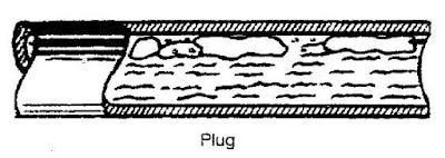
Two phase gas liquid flow is commonly occur in any oil & gas production and processing system. Several flow patterns can occur in two phase gas liquid flow. There are Bubble flow (with minimum vapor bubble), Plug flow, Stratified flow, Wavy flow, Slug flow, Annular flow and Mist/Dispersed flow (with minimum liquid droplet). See following images.


Obvious Location
Present of two phase gas liquid may be obvious and be easily identified during development phase. Typical example are Full-Well-Stream (FWS) production which possibly producing hydrocarbon in gas and liquid form. Formation water, condensed water, mercury, and injected chemical (e.g. corrosion inhibitor, hydrate inhibitor, etc) in liquid form, wax in slurry form and sand in solid form may also present in the FWS, which typically result complicated multiphase form. Partial stabilized condensate travel long distance experience high pressure drop lead to vaporization. Vapor travel long distance experience ambient and J-T (isenthalpic process) cooling lead to condensation. Hot saturated vapor is cooled by air cooler or heat exchanger results condensation, vapor or liquid passing through turbine experience isentropic process, etc. These streams are obvious and can be easily identified in process simulation. Generally example are :
Present of two phase gas liquid may be obvious and be easily identified during development phase. Typical example are Full-Well-Stream (FWS) production which possibly producing hydrocarbon in gas and liquid form. Formation water, condensed water, mercury, and injected chemical (e.g. corrosion inhibitor, hydrate inhibitor, etc) in liquid form, wax in slurry form and sand in solid form may also present in the FWS, which typically result complicated multiphase form. Partial stabilized condensate travel long distance experience high pressure drop lead to vaporization. Vapor travel long distance experience ambient and J-T (isenthalpic process) cooling lead to condensation. Hot saturated vapor is cooled by air cooler or heat exchanger results condensation, vapor or liquid passing through turbine experience isentropic process, etc. These streams are obvious and can be easily identified in process simulation. Generally example are :
- Full Well Stream (FWS)
- Partial stabilized condensate with long pipeline
- Saturated vapor with long pipeline
- Liquid stream from separator passing a level control valve
- Downstream of Air cooler / Heat exchanger
- Turbine outlet
- Hot fluid mix with cool fluid continuously
Recommended :
Subscribes to FREE Hydrocarbon Processing
 Non-obvious Location
There are certain stream may be not so obvious and may not be easily identified in process simulation. Hot saturated vapor flow in long pipe experience heat loss to ambient and frictional loss, condensation begin and two phase flow (i.e. mist flow, annular flow). Cold saturated or partial subcooled liquid experience frictional loss due to fittings, piping, etc and ambient heating results vaporization and two phase flow (i.e. bubble flow, wavy flow, slugging flow). Hot stream mix with cold stream may results equilibrium change and lead to two phase. Typical area is flare collection system. Hydrocarbon in process vessel at pressure once it is drained to drain collection header may flash and lead to vaporization. Generally example are :
Subscribes to FREE Hydrocarbon Processing
Non-obvious Location There are certain stream may be not so obvious and may not be easily identified in process simulation. Hot saturated vapor flow in long pipe experience heat loss to ambient and frictional loss, condensation begin and two phase flow (i.e. mist flow, annular flow). Cold saturated or partial subcooled liquid experience frictional loss due to fittings, piping, etc and ambient heating results vaporization and two phase flow (i.e. bubble flow, wavy flow, slugging flow). Hot stream mix with cold stream may results equilibrium change and lead to two phase. Typical area is flare collection system. Hydrocarbon in process vessel at pressure once it is drained to drain collection header may flash and lead to vaporization. Generally example are :
- Saturated vapor within plant (condensation)
- Cooled or subcooled liquid within plant (vaporization)
- Flare collection
- Hydrocarbon drain collection
Problems
Two phase gas liquid flow can cause several destructive problems. There are :
- Impingement erosion
- Splashing erosion
- Cavitation erosion
- Flashing erosion
- Flow induced vibration
- Surge / hammer
- Noise
- Decrease process performance
- Phase separation
Two phase gas liquid flow can lead to impingement, cavitation & flashing erosion. Two phase gas liquid flowing fluid where heavy phase is accelerated with light phase and induced high momentum and shearing stress on surface. Slugging flow in vapor-liquid system with large slug hammering on surface induce high momentum with medium velocity and high mass flux. Mist flow with droplet accelerate at vapor velocity induce high momentum with high velocity and low mass flux. Both induce high shear stress on the surface and increase material removal rate.
Flow Induced Vibration
High velocity compressible fluid in pipe is moving in turbulence pattern. Turbulence flow will induced vibration on pipe. Once the flow induced vibration frequency meeting the natural frequency of pipe support, resonance occur can lead to severe movement of pipe support. Present of two phase gas liquid flow can generate different level of frequency and increase possibility of resonances.
Surge & Hammer
Two phase gas liquid slugging and high velocity gas moving liquid at similar speed, severe vibration can occur when liquid slug is knocking/splashing on the pipe wall, especially at bend and elbow. Hot steam mix with cold condensate at the collection header results sudden steam vapor collapse. The collapse vapor results sudden lower pressure will lead sudden replacement of surrounding condensate. Sudden movement of condensate can results significant movement of condensate as well as piping and pipe support. Under designed pipe support may fail due to severe vibration.
Quick opening of valve for incompressible, multiphase and gas/vapor will results sudden change in momentum (0 to +mv) and subsequently instantaneous peak force acting on the piping. This phenomena is commonly occurs in control valve (CV), Blowdown valve (BDV) and pressure relief device i.e. pressure relief valve (PRV) and rupture disc (RD). The instantaneous peak force acting on the piping may potentially lead to piping failure.
Noise
Above phenomenon such as Impingement, Splashing, Cavitation & Flashing Erosion, Flow Induced Vibration and Surge & Hammer may also generate noise which potentially exceeded the allowable noise limit.
Affect process performance
In oil and gas production, condensate-produced water bulk separation occur in slug catcher / inlet receiver follow by a Condensate separator. Some process design may include a filter coalescing separator to promote water droplet coalescing (using coalescing element) and separation before it is sent to Condensate stabilization. Condensate at saturation point from Condensate separator feeding to Filter Coalescing separator will experience frictional drop and potential lead to vaporization. Vapor will accumulate in the filter coalescing separator and seriously affect Coalescing activity in Filter Coalescing Separator.
Plate heat exchanger (PHE) is used in Solvent e.g. Amine, MEG, TEG, etc regeneration to recover heat from lean solvent stream and promote energy saving. Hydrocarbon and / or vapor bubble under carry from Solvent Absorber to PHE potentially accumulate in the PHE and seriously affect the heat transfer in PHE.
Phase Separation - Mal-Distribution
Air cooler used for fluid cooling is widely used in Oil & Gas and Petrochemical plant. Hot fluid is fed to a Inlet header box, distribute fluid into tubes (normally finned) where cooling take place and cooled fluid is collected in the Outlet header box. If hot two phase gas liquid fluid feeding to the inlet header box, liquid with higher momentum tends to flow preferential path (straight) compare to vapor with lower momentum. The lead to serious vapor-liquid mal-distribution. Fluid (vapor dominant) feed to tube closer to inlet possibly over cooled whilst fluid (liquid dominant) feed to tube further from inlet possibly under cooled. For large duty air cooling system, fluid may further distribute into multiple header boxes and multiple unit air cooler, this will further create mal-distribution of fluid.
Knowing the problems caused by two phase gas liquid flow, identification of potential two phase gas liquid becoming an important activity during design phase. Process engineer shall take extra care during design phase and provide necessary prevention measures to minimize / avoid occurrence of two phase flow.
Related Post
- Facts about Erosion & Erosion-Corrosion
- Erosion & Erosion - Corrosion
- Several Criteria and Constraints for Flare Network - Process
- Assess Potential Piping Failure Due to Valve Quick Opening with Two-Phase Vapor Liquid
- How Fluid Characteristic affect 2 phase Relief via PSV on Liquid filled Vessel Exposing to External Fire
Labels: Fluid Flow, hydrualic
posted by Webworm, 6:59 AM


0 Comments:
Post a Comment
Let us know your opinion !!! You can use some HTML tags, such as <b>, <i>, <a>
Subscribe to Post Comments [Atom]
Home:
<< Home