Thursday, December 15, 2011
Earlier post "Mal-Distribution of Phases at T-Junction Phenomenon" and "Stagnant Liquid In Inclined Parallel Pipe Downstream of T-Junction" have shown two phase flow mal-distribution and stagnant liquid phenomenon at T-junction or splitting tee.
The flow distribution from a manifold to parallel channels is becoming of interest in predicting the heat transfer performance of heat exchangers. As discussed, due to maldistribution of two phase flow at T-junction, flow rates through the channels to each heat exchanger are not uniform. In the extreme case, there is almost no flow through some of them (i.e. stagnant liquid phenomenon). As of today, there is still no general way to predict the distribution of two-phase mixtures at header–channel junctions (T-junction).
Simulation studies by Bernoux et al. (2001) with two-phase distribution at the inlet manifold of compact heat exchangers, results showed that the vapor distribution to the channels became uniform with the increase of the mass quality (Xv), but the liquid distribution still remained unbalanced. Besides, the liquid distribution through the channels was not much sensitive to the mass flux (MFlux).
Flow behavior studies (by Osakabe et al, 1999) in a horizontal square header (with each side being 40 mm) connected to four parallel vertical tubes (10 mm in diameter) for the bubbly and slug flows at the inlet, largest amount of the liquid flow into the first tube for a low mass quality (Xv) flow in the header; however, the tendency of mal-distribution is reduced with the increase of the mass quality (Xv) inside the header.
Flow behavior at one junction has no influence on that at the next junction. On the other hand, for the most of the compact heat exchangers, the distance between the channels is comparable to or even smaller than the header size (hydraulic diameter), flow interaction between the junctions has to be taken into account.
Infact, behavior of flow separation in small T-junctions appeared different from that in the large T-junctions. There are strong interaction between each T-junctions. The flow behavior at one T-junction is strongly influenced by other T-junction especially when the distance between the T-junction is equivalent to or smaller than the hydraulic diameter of the header (as reported by Lee & Lee, 2004).

Further investigation on two-phase flow behavior at the upward header co-current flow and horizontal rectangular parallel channels and simulating the corresponding parts of compact heat exchangers shown that intrusion depth of the channels into header affects flow distribution of the liquid-phase. Less amount of liquid was separated out through the channels at the rear part except near the end-partition with the zero intrusion depth, Reversed trend observed for deeper intrusion. This indicated that a uniform distribution could be obtained by adjusting the intrusion depth. Deeper intrusion channel promote mixing effect and hence the uniform distribution to each outlet.
Above shown that mal-distribution of two phase flow at T-junctions affects by many factors i.e. vapor mass quality, flow pattern, distance of T-junction, size of T-junction and header size, penetration of T-junction into header, etc. Infact, above only several factors affecting mal-distribution, there are many more factors affecting it. In a compact heat exchanger i.e. Plate Fin Heat Exchanger (PFHE), Brazed Aluminum Heat Exchanger (BAHX), gas & liquid fraction flow from header to each channel may be different from tube to tube. This could seriously affects the heat transfer performance of the heat exchanger. Not only that performance varies at each channel would lead to change in temperature profile, and hence thermal stress profile of heat exchanger which increase the fatigue cracking tendency and life span of the heat exchanger.
Related Topics
- Stagnant Liquid In Inclined Parallel Pipe Downstream of T-Junction
- Mal-Distribution of Phases at T-Junction Phenomenon
- Problems Caused by Two Phase Gas-Liquid Flow
- Slugging & Slugcatcher
- Liquid Slug Stabiliser - Another type of slugcatcher
- Assess Potential Piping Failure Due to Valve Quick Opening with Two-Phase Vapor Liquid
- How Fluid Characteristic affect 2 phase Relief via PSV on Liquid filled Vessel Exposing to External Fire
Labels: Fluid Flow, Oil and Gas


Wednesday, December 14, 2011
In earlier post "Mal-Distribution of Phases at T-Junction Phenomenon", there were several mal-distribution phenomenon shown. In this post there is another phenomenon where engineer may not see or feel it and it may not has any consequence. It is flow preferential and stagnant liquid phenomenon in a inclined splitting tee.

Taitel et al (1999 & 2003) has investigated two phase flow with common inlet, split at impacting T-junction, flow in inclined parallel pipes and merge at common outlet. Flow splitting of gas and liquid in four (4) parallel pips was investigated. Experimental results were obtained for 0°, 5°, 10° and 15° inclinations.
For the horizontal case (0°) the flow takes place in all of the 4 pipes, usually with an "approximately" even splitting. For the inclined pipes various flow configuration could take place. For low liquid and gas flow rates the two-phase mixture prefers to flow in a single pipe while stagnant liquid fills part of the other three (3) pipes. As the flow rates of liquid and gas increase, flow in two, three and eventually in four pipes takes place.
For the horizontal case (0°) the flow takes place in all of the 4 pipes, usually with an "approximately" even splitting. For the inclined pipes various flow configuration could take place. For low liquid and gas flow rates the two-phase mixture prefers to flow in a single pipe while stagnant liquid fills part of the other three (3) pipes. As the flow rates of liquid and gas increase, flow in two, three and eventually in four pipes takes place.
This has provided some insight and idea to the designer and operator, there is a minimum flow for two phase flow in parallel pipes. Under turndown operation, there is possible flow in single pipe while liquid column stagnant in the other pipe. Whenever increase production, it shall be gradually increase to avoid large liquid volume feed to the downstream equipment and pipe failure due to slugging flow in downstream pipe.
Another potential issue is present of heavy sand in the two phase flow. Heavy sand will tend to stays and accumulates in the stagnant liquid and potentially partially block the pipes. Therefore, this stagnant liquid phenomenon should be checked and taken care during design and operation phase.
- Mal-Distribution of Phases at T-Junction Phenomenon
- Problems Caused by Two Phase Gas-Liquid Flow
- Slugging & Slugcatcher
- Liquid Slug Stabiliser - Another type of slugcatcher
- Assess Potential Piping Failure Due to Valve Quick Opening with Two-Phase Vapor Liquid
- How Fluid Characteristic affect 2 phase Relief via PSV on Liquid filled Vessel Exposing to External Fire
- Facts about Erosion & Erosion-Corrosion
Labels: Fluid Flow, Oil and Gas
Monday, December 12, 2011
Multiphase flow, primarily gas-liquid flow, exists in chemical, power, oil/gas production and refining plants. Multiphase flow is very complex phenomena. Most application has considered that fluid split at T-junction, all phases will be evenly split between the run and branch. In reality, maldistribution of phase occurred at T-junction. Each phase has their preference route. This maldistribution phenomenon has been experienced in many industrial applications.
Mal-Distribution of Phases at T-Junction Phenomenon
In the Oil and gas, refinery, petrochemical and chemical plant, pipes has been widely used to transfer product from equipment to equipment for further processing. Starting from offshore platform, oil & gas produce from reservoir via wellheads, partially stabilized in production separators (sometime produced water knocked-out in the production separator and further re-inject back to reservoir or treated and disposed locally), separated gas and condensate/oil will be transport to onshore via separate long pipelines. Along the pipeline, external cooling by ambient and seawater couple with pressure drop in the pipeline, condensation will occur in some places in the pipeline and two phase flow initiated. Gas with condensate arrived onshore will be dumped into a multi-fingers slugcatcher. Impacting Tee will be used to split the flow between the fingers. Gas-condensate is then separated in the slugcatcher via slight-inclined horizontal pipe with vertical Tee. At the impacting Tee, maldistribution of gas & condensate between the branches are observed in reality. These ended-up some fingers are over capacity and some under capacity.
Production from several wellhead platforms will be send to central processing platform (CEP) for partial separation and stabilization via long subsea pipeline. Due to geographical arrangement of wellhead platforms and well develop at different phases, those pipelines could be mixed at topside or subsea using Tee.
Gaslift used to enhance oil productivity will be supplied from central processing platform via long gaslift pipeline. The gaslift pipeline will be delivered from one platform to another platform. Tee will be used to split the gas flow. In order to avoid condensation, generally the gaslift dew point will be depressed to avoid condensation along the gaslift pipeline. Inefficient performance and mal-operation of topside gaslift dew point control will result saturated gas feed into the gaslift pipeline. Similar to above gas pipeline, condensation occurred in the long pipeline due to external cooling and pressure drop and affect the proper split.
| Featured Resources: | |
 | LNG Industry Provides global coverage of the entire LNG value chain.... >> |
Oil production system producing high viscosity oil, steam will be injected to enhance oil recovery. Multiple steam injection is implemented to ensure proper distribution of steam and increase the oil recovery efficiency. Steam supply from main header will be distributed to all injection points via tees. In some cases, steam is supplied from central utility production unit which is far away from the users, cooling by external (imperfect insulation) and pressure drop along header will lead to two phase flow. Maldistribution of steam-condensate at each split will result oil recovery performance dropped.
The LPG or natural gas will be supplied to users such as factory, household, etc. A lot of pipeline and tees will be used for transfer and splitting the flow. Similar to above gas pipeline, condensation could occur in the pipeline and distribution network, malditribution at the splitting tee and could result some users received large amount of condensate.
In the chemical plant, there are two phase flow gas (with low liquid loading) feeding to condenser. In order to increase operability and turndown, multiple condensers will be installed. When the plant is operate under partial capacity, some condensers will be put in operation. Maldistribution occurred at splitting tee result some condenser over capacity (fed with high liquid loading) and the some condenser under capacity (fed with low liquid loading).
Phase maldistribution has been reported from offshore platforms in the UK North Sea. Two main (phase) vessel separators has been installed in parallel in order to enable production to continue albeit at a reduced level if there was a need for maintenance or modification of a separator. To ensure an even split of the phases, an impacting T-junction was employed. When the system was started up it was found that one separator received most of the gas whilst the other got most of the liquid. Inspection of the pipework upstream of the junction showed that bend located upstream result centrifuging of the phases and presenting each outlet with substantially one phase
There are others phase maldistribution observed on T-junction. For example, phase separation in main coolant piping of light water nuclear reactor (LWR) can play significant role in the effectiveness of emergency core cooling (ECC) system during analysis of Loss-of-coolant-accident (LOCA).
Therefore, in handling vapor near condensation point or two phase flow, phase separation is one of the phenomenon shall be analyzed to minimize mal-distribution.
Related Topics
Related Topics
- Problems Caused by Two Phase Gas-Liquid Flow
- Assess Potential Piping Failure Due to Valve Quick Opening with Two-Phase Vapor Liquid
- How Fluid Characteristic affect 2 phase Relief via PSV on Liquid filled Vessel Exposing to External Fire
- Facts about Erosion & Erosion-Corrosion
- Erosion & Erosion - Corrosion
- Several Criteria and Constraints for Flare Network - Process
Labels: Fluid Flow, Oil and Gas
Thursday, August 12, 2010
Design and operating guidelines for subsea oil systems have been developed to ensure the control of hydrates, wax, and other solids, which may impede flow. System designs are primarily driven by the need to avoid the formation of a hydrate plug in any portion of the system. Remediation of hydrate plugs may require system shut-in for weeks or even months. Design and operation guidelines for wax management are also well developed. Asphaltenes present a new challenge to subsea system design and operation. A number of projects now under development (Europa, Macaroni) are likely to experience some asphaltene deposition in flowlines and wellbores. Strategies have been developed to manage asphaltenes, but have not yet been tested in the field. The design and operating guidelines for control of solids in subsea oil systems are a product of the flow assurance process.
by S. E. LORIMER & B. T. ELLISON, Shell Deepwater Development Inc.
Download
Related Topic
- Introduction to Oil & Gas Production Presentation
- Oil Characterization Method in HYSYS
- An Introduction to Oil & Gas Production...
- Gas Processing, NGL Extraction & LPG Fractionation
- Typical Gas Processing Flow Scheme
Labels: E-Doc, Oil and Gas
Sunday, May 16, 2010
Earlier post “Seawater Treatment & Injection For Well Maintenance & Increase Productivity” discussed about the water source and its associated water injection treatment. Seawater will be filtered with coarse and fine filters to remove particles smaller than 2 micron with 98% removal efficiency. Filtered seawater will be deaerated to bring the Oxygen concentration down to 20 ppb. Oxygen scavenger is then injected to further reduce the Oxygen concentration down to 10 ppb in order to reduce corrosion to cost effective level. Chlorine is injected to injection water to avoid bacteria and alga growth.
Residue Oxygen in injection may still result corrosion in the pipeline. How much it affect the corrosion of Carbon steel pipeline ? Present of Chlorine is known further increase corrosivity of injection water. How this impact the corrosion water ? Increase of water velocity in pipeline will increase flow induced erosion of pipeline. Simultaneous erosion (flow induced) - corrosion (Oxygen & Chlorine) present in the pipeline. How water velocity affect corrosion ? What is the water velocity limit ? This post will present a water velocity limit with varies of oxygen concentration (and Chlorine content) in water .
Oxygen corrosion in water injection pipeline is controlled by diffusion rate of Oxygen into Cathodic with following reaction :

Steel is corroded on the Anodic side with following reaction :

Water Injection Velocity Limit
Chlorine Free
water injection velocity limit (Vmax)of Carbon steel pipeline is :

With Chlorine concentration of 0.5 ppm
water injection velocity limit (Vmax)of Carbon steel pipeline is :

CA = Corrosion Allowance (mm)
Y = Life span (years)
CO2 = Oxegen concentration (ppb)
T = Seawater temperature (degC)
ρw = Seawater density (kg/m3)
Example
Refer following figures for water injection velocity limit (m/s) versus oxygen level (ppb) with Chlorine free and 0.5 ppm Chlorine.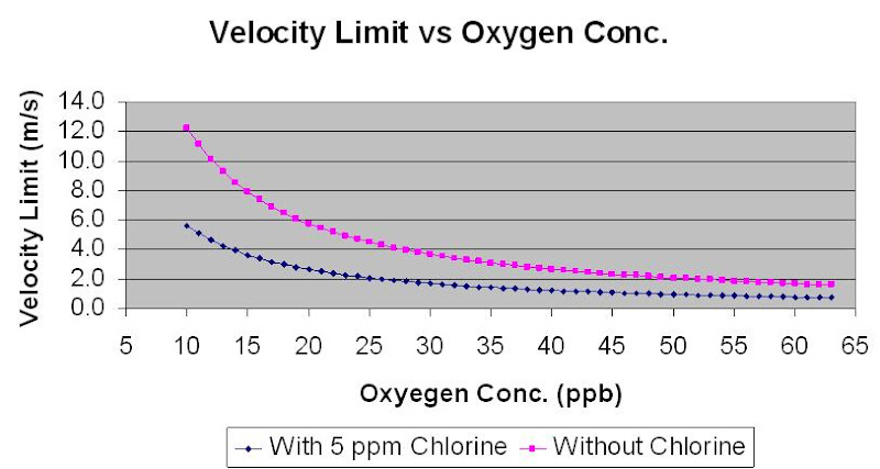
Above figures was based on
Corrosion Allowance, CA = 3.0mm
Life span (years), Y = 20 years
Seawater temperature, T = 25 degC
Seawater density, ρw = 1030 kg/m3
At 20 ppb of Oxygen concentration, the velocity limit is 5.7 m/s (Chlorine free) and 2.6 m/s (Chlorine = 0.5 ppm).
At 10 ppb of Oxygen concentration, the velocity limit is 12.2 m/s (Chlorine free) and 5.6 m/s (Chlorine = 0.5 ppm).
Ref :
1) J.W. Oldfiedl, G.L. Swales, B.Todd, “ Corrosion of Metals in Deaerated Seawater”, Proc. Of the 2nd Corrosion Conference, held Jan, 1981
2) J.M. Drugli, T. Rogne, “ Effect of Oxygen and Chlorine Content on the Corrosion Rate of Carbon Steel Welds in Injection Water” CORROSION/93 paper no 65
3) Mamdouh M. Salama, “Erosion Velocity Limits for Water Injection Systems”, 1993
Related Topics
- Seawater Treatment & Injection For Well Maintenance & Increase Productivity
- Chloride Stress Corrosion Cracking & Use correct MOC for seawater service
- How a Chloride Stress Corrosion Cracking Lookslike ?
- Crevice Corrosion Engineering Guide Software for Stainless Steels
- Different Equation for Pitting Resistance Equivalent Number (PREN)
- Guideline on Use of MR0175 / ISO15156
Labels: Chloride Stress Corrosion Cracking, Oil and Gas
Sunday, May 9, 2010
Water injection is common applied in maintaining crude reservoir to increase crude productivity. For offshore facilities, seawater is commonly lifted and treated for water injection purpose. The water injection rate is subject to reservoir condition and crude production. Particle present in seawater potentially results formation blockage and reduce injectivity. Oxygen present in seawater potentially results severe corrosion of transfer pipeline and injection tubing. Alga and bacteria present in seawater may potentially growth result corrosion and formation blockage. Therefore seawater use for injection shall be treated prior transfer and injection.
Seawater Treatment
Seawater used for water injection will goes through a series of treatments :- Filtration - remove particles
- Deaeration - remove oxygen
- Chemical injection - prevent foaming, corrosion, alga / bacteria growth
Seawater lifted will pass through filtration package. The filtration package commonly consist of two levels of filtration. First level filtration is also known as Coarse Filtration where the filter is provided to remove particle with size larger than 80-100 micron. The common required removal efficiency is 98%. The filter is normally equipped with auto-backwash facilities e.g. rotational backwash motor. Second level filtration is also known as Fine Filtration where the filter is provided to remove particle with size large than 2 micron with removal efficiency of 98%. Similarly this filter is equipped with auto-backwash facilities with the assistance of blower.
Deaeration
Seawater is aerated in ambient contains high oxygen contents. Typically the seawater is considered saturated with oxygen and this quantity is sufficient to results significant corrosion in transfer pipeline and injection tubing. Corrosion is increased with increased in quantity of oxygen in seawater. The oxygen level in the seawater is commonly deaearated down to 20-40 ppb in the deaeration column. Oxygen scavenger is injected downstream of deaeration column to further bring the oxygen level down to 10-20 ppb. Two main methods are used for deaeration :
- Vacuum deaeration
- Gas stripping
Chemical injection
CoagulantPresent of large quantity of small particle may results particle passing filtration, accumulates, agglomerate and finally results plugging of formation. Coagulant may be required to be injected upstream of filtration package to promote particle coagulation and filtration.
Anti-Foam
Seawater may be contaminated with hydrocarbon when it is lifted. Seawater used for processing cooling, any leakage in the seawater heat exchanger also result Hydrocarbon present in the seawater. Presented of hydrocarbon in seawater may results foaming in deaeration column. Therefore, anti-foam may be required to suppress foaming.
Biocide (Hypo-chloride)
Bacteria presents in seawater may results corrosion and alga growth which release solid waste to promote formation plugging. Hypo-Chloride is injected to prevent bacteria and alga growth. One shall take note present Chlorine is seawater may also results corrosion. Concentration subject to type of Biocide, however 5 ppm level could be good guess.
Corrosion Inhibitor
Present of Chlorine, residue bacteria and residue oxygen promote corrosion. Therefore corrosion inhibitor (CI) is injected to prevent / minimize corrosion. Concentration subject to type of CI, however 5 ppm level could be good guess.
Related Topics
- Chloride Stress Corrosion Cracking & Use correct MOC for seawater service
- How a Chloride Stress Corrosion Cracking Lookslike ?
- Crevice Corrosion Engineering Guide Software for Stainless Steels
- Different Equation for Pitting Resistance Equivalent Number (PREN)
- Guideline on Use of MR0175 / ISO15156
Labels: Chloride Stress Corrosion Cracking, Oil and Gas
Tuesday, April 13, 2010
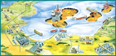
Oil has been used for lighting purposes for many thousand years. In areas where oil is found in shallow reservoirs, seeps of crude oil or gas may naturally develop, and some oil could simply be collected from seepage or tar ponds. Historically, we know of tales of eternal fires where oil and gas seeps would ignite and burn. One example 1000 B.C. is the site where the famous oracle of Delphi would be built, and 500 B.C. Chinese were using natural gas to boil water. But it was not until 1859 that "Colonel" Edwin Drake drilled the first successful oil well, for the sole purpose of finding oil.
Recommended :

Earlier post "An Introduction to Oil & Gas Production..." has presented a handbook to provide readers with an interested in the oil and gas production industry an overview of the main processes and equipment. This handbook will also provides enough detail to let the engineer get an appreciation of the main characteristics and design issues.,
Similarly, Ta Quoc Dung has made a presentation on "Introduction to Oil & Gas Production". This presentation consists of five (5) chapters.
- Introduction
- Process overview
- Performance of Flowing well
- Artificial lift
- Enhanced oil recovery
Going through this presentation, it allows reader
Download
Thanks to Ta Quoc Dung
Related Topic
- to have overview of Petroleum Production Technology
- to understand the role of Production Engineer in a Petroleum Operating Company
- to understand production system and its onshore and offshore facilities
- to understand concept of inflow performance, lift performance and integrated nature
- to understand enhanced oil recovery process
Download
Thanks to Ta Quoc Dung
Related Topic
Labels: Oil and Gas
Monday, March 9, 2009
Recommended :
Tips on Succession in FREE Subscription
Subscribe FREE - Processing Magazine
 The petroleum characterization method in Aspen HYSYS converts laboratory analysis of condensates, crude oils, petroleum cuts, and coal-tar liquids into a series of discrete hypothetical components. These petroleum hypo components provide the basis for the property package to predict the remaining thermodynamic and transport properties necessary for fluid modeling. Aspen HYSYS produces a complete set of physical and critical properties for the petroleum hypo components with a minimal amount of information. However, the more information you supply about the fluid, the more accurate these properties will be, and the better Aspen HYSYS will predict the fluid's actual behavior.
Tips on Succession in FREE Subscription
Subscribe FREE - Processing Magazine
The petroleum characterization method in Aspen HYSYS converts laboratory analysis of condensates, crude oils, petroleum cuts, and coal-tar liquids into a series of discrete hypothetical components. These petroleum hypo components provide the basis for the property package to predict the remaining thermodynamic and transport properties necessary for fluid modeling. Aspen HYSYS produces a complete set of physical and critical properties for the petroleum hypo components with a minimal amount of information. However, the more information you supply about the fluid, the more accurate these properties will be, and the better Aspen HYSYS will predict the fluid's actual behavior.In this example, the Oil Characterization option in Aspen HYSYS is used to model a reservoir fluid. The fluid is a combined gas and oil stream. Read more in Oil Characterization.
Download
Related Topic
Download
Related Topic
Labels: HYSYS, Oil and Gas
Saturday, September 6, 2008
Display problem ? Click HERE
Recommended :
- Subscribe FREE - Chemical Processing
- Tips on Succession in FREE Subscription

Oil has been used for lighting purposes for many thousand years. In areas where oil is found in shallow reservoirs, seeps of crude oil or gas may naturally develop, and some oil could simply be collected from seepage or tar ponds. Historically, we know of tales of eternal fires where oil and gas seeps would ignite and burn. One example 1000 B.C. is the site where the famous oracle of Delphi would be built, and 500 B.C. Chinese were using natural gas to boil water. But it was not until 1859 that "Colonel" Edwin Drake drilled the first successful oil well, for the sole purpose of finding oil.
- Subscribe FREE - Chemical Processing
- Tips on Succession in FREE Subscription
Oil has been used for lighting purposes for many thousand years. In areas where oil is found in shallow reservoirs, seeps of crude oil or gas may naturally develop, and some oil could simply be collected from seepage or tar ponds. Historically, we know of tales of eternal fires where oil and gas seeps would ignite and burn. One example 1000 B.C. is the site where the famous oracle of Delphi would be built, and 500 B.C. Chinese were using natural gas to boil water. But it was not until 1859 that "Colonel" Edwin Drake drilled the first successful oil well, for the sole purpose of finding oil.
Oil & Gas Production Handbook
There are much of equipment described in standards, equipment manuals and project documentation, however, material to quickly provide reader an overview of the entire upstream area found to be pretty minimum. This is a handbook been compiled to provide readers with an interested in the oil and gas production industry an overview of the main processes and equipment. Above handbook will also provides enough detail to let the engineer get an appreciation of the main characteristics and design issues.,
Download (Click HERE)
Related Posts
- 3 Most Important & FREE Magazines That I Read...
- Understand Boiler Efficiency
- Non - Technical Quick References for a Chemical & Process Engineers
- Instrumentation and Formulae & Conversion...
- R&D engineer, Academician and Student...Don't miss this !
- FREE E-book........A Heat Tranfer Textbook
- WOLVERINE - Offer FREE Heat Transfer Engineering Databook...
- Workbook for Chemical Reactor Relief System Sizing
- A must have book...Emergency Relief System Design Using DIERS Technology
Labels: E-Doc, Ebook, Education, Learning, Oil and Gas
Thursday, October 11, 2007
(Click photo for better view)


Construction of platform jacket (short cylinder)

(Begin installation of topsite)

(Living quarter installation)


(Construction completion is around the corner)


(Float off & Loadout)


(Sailing...)

(Installed & in Production)
More pictures...Click HERE
More pictures...Click HERE
Related Topics :
- New Concept of Floating Unit-Part 1
- Floating Gas Refinery Unit
- Launching of Wilhelm Busch
- Gas Processing, NGL Extraction & LPG Fractionation
Labels: Floating Unit, Oil and Gas
Wednesday, October 10, 2007
I have seen many Floating Production Storage Offloading (FPSO) either is new build and /or conversion from existing ship. Somehow all FPSO are in rectangle shape with rather sharp head. The other type of Floating Production Unit (FPU) which is in a rather square shape.
The following are some new type of floating platforms. There consist of Floating Accommodation Unit (FAU), Floating Drilling Production Storage Offloading Unit (FDPSOU), Floating Gas Turbine Generator Unit (FGTG) and Floating Mobile Subsea Vehicle Unit (FMSVU).
Floating Accommodation Unit (FAU)

(Click image for better view)
Floating Drilling Production Storage Offloading Unit (FDPSOU)

(Click image for better view)
Floating Gas Turbine Generator Unit (FGTG)
(Click image for better view)
Floating Mobile Subsea Vehicle Unit (FMSVU)
(Click image for better view)
All units are potable and inter-link between each and other. They can be added and relocated according operation demand.Floating Mobile Subsea Vehicle Unit (FMSVU)
(Click image for better view)
These units have been constructed in YANTAI yard, China in 2005. Next post will includes the actual photos of these units.
Related Topics :
Labels: Floating Unit, Oil and Gas
