Saturday, October 4, 2008
Display problem ? Click HERE
Recommended :
Subscribe FREE - Processing Magazine
 A gas liquid separator is used for bulk separation and mist eliminator i.e. vane type, mesh type, cyclone type) are used to promote liquid drop coalescence and separation from gas. Souder-Brown equation has been widely used in Oil and gas industry to size a gas liquid separator with and without mist eliminator.
Subscribe FREE - Processing Magazine
A gas liquid separator is used for bulk separation and mist eliminator i.e. vane type, mesh type, cyclone type) are used to promote liquid drop coalescence and separation from gas. Souder-Brown equation has been widely used in Oil and gas industry to size a gas liquid separator with and without mist eliminator.Generally the K factor as proposed in GPSA has been used by many engineers. Following figure tabulate the K factor may be used for horizontal, vertical, vertical scrubber and others separator for special services.

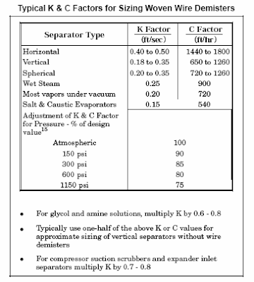
On the other hand, there are no indication of the liquid droplet size can be removed. The following is intended to studies the limiting droplet size based on the K factor used for horizontal, vertical and vertical scrubber. In some event, it may be a useful information especially when there is droplet size limitation of downstream equipment i.e compressor.
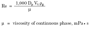
For a droplet in free fall (gravity action), the droplet terminal velocity is as follow :

By arranging in the Souders-Brown equation :
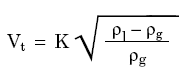
And the K factor is as follow :
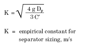
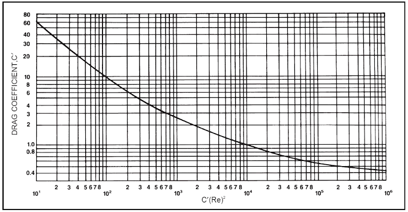
The drag coefficient (C') can be read from the following figure.
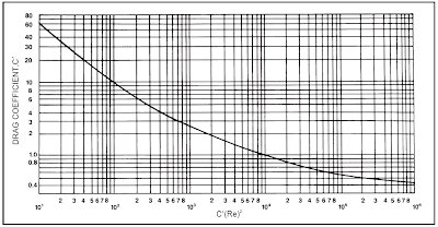
where Re is Reynolds number as follow :
For a vapor and liquid with the following condition and properties :
The limiting liquid droplet size are
Horizontal separator without mist eliminator : 350 -540 micron
Vertical separator without mist eliminator : 160 -400 micron
Vertical scrubber without mist eliminator : 125-290 micron
Related Topic
(Click to view large image)
where Re is Reynolds number as follow :
Basis
- Pressure = Atmosphere
- Temperature = 40 degC
- Molecular Weight = 20-40
- Compressibility factor = 0.9
- Liquid density = 500 - 850 kg/m3
- K factor for horizontal separator is 0.06 -0.075 m/s
- K factor for vertical separator is 0.025-0.055 m/s
- K factor for vertical scrubber is 0.018 -0.039 m/s
The limiting liquid droplet size are
Horizontal separator without mist eliminator : 350 -540 micron
Vertical separator without mist eliminator : 160 -400 micron
Vertical scrubber without mist eliminator : 125-290 micron
Related Topic
- Oil - Water Separator for Household
- Properly Simulate a Separator with Demister in HYSYS
- Factors you shall Consider for Separator with Boot
- Slugging & Slugcatcher
- Quick Understanding & Estimation of Mist Eliminator in Gas-Liquid Separator
- KnitMesh...Good Articles on Mist eliminator still available FREE...
- ACS - Design manual for Mist Eliminators, Trays, Packing, Internals...All in distillation columns
Labels: Separation, Separator
Saturday, September 27, 2008
Display problem ? Click HERE
In oil and gas production, formation water and condensed water present in oil and gas. These water cause hydrate formation in offshore transfer pipeline, severe slugging, corrosion, etc. They are contaminant shall be removed to meet the oil and gas specification. Water separated from oil and gas is normally contaminated with oil which can be in dispersed and diluted form. If the contaminated water is separated from a 2 phase or 3 phase separator , the oil contaminant level can be as high as 3000 ppmw. This level is far higher than the acceptable level of 30-40 ppmw. The contaminated water required further treatment.
Recommended :
Subscribe FREE - Processing Magazine
Contaminated water treatment are complicated. There are physical separation which includes solid-liquid separation, liquid-liquid separation, diluted component removal, etc as well as chemical treatment and biological treatment. In the physical separation, the normal technology used are hydrocyclone, corrugated plate pack unit, floatation unit, etc.
Similarly, the wastewater from daily usage i.e. wash water from kitchen is contaminated with oil. The oil and water may be separated with above mentioned unit. Following video clips presented a basic plate pack unit which separated oil from water before the water is discharged to public drainage. The separation principle is basically promote oil droplet coalescence in plate pack follow by gravity separation. The oil level in treated water can reach 20 ppmw level and possibly discharge directly to public drainage network (subject to local rules). The separated oil can be collected and storage in a storage tank and ready to be pumped to waste treatment plant for extraction.
Oil water separation process (video clip)
Oil water pre-module (video clip)
Oil water separation box (video clip)
Related Topic
Recommended :
Subscribe FREE - Processing Magazine
Contaminated water treatment are complicated. There are physical separation which includes solid-liquid separation, liquid-liquid separation, diluted component removal, etc as well as chemical treatment and biological treatment. In the physical separation, the normal technology used are hydrocyclone, corrugated plate pack unit, floatation unit, etc.Similarly, the wastewater from daily usage i.e. wash water from kitchen is contaminated with oil. The oil and water may be separated with above mentioned unit. Following video clips presented a basic plate pack unit which separated oil from water before the water is discharged to public drainage. The separation principle is basically promote oil droplet coalescence in plate pack follow by gravity separation. The oil level in treated water can reach 20 ppmw level and possibly discharge directly to public drainage network (subject to local rules). The separated oil can be collected and storage in a storage tank and ready to be pumped to waste treatment plant for extraction.
Oil water separation process (video clip)
Oil water pre-module (video clip)
Oil water separation box (video clip)
Related Topic
- Properly Simulate a Separator with Demister in HYSYS
- Factors you shall Consider for Separator with Boot
- Slugging & Slugcatcher
- Quick Understanding & Estimation of Mist Eliminator in Gas-Liquid Separator
- KnitMesh...Good Articles on Mist eliminator still available FREE...
- ACS - Design manual for Mist Eliminators, Trays, Packing, Internals...All in distillation columns
Labels: Separation, Separator
Wednesday, May 14, 2008
Display problem ? Click HERE
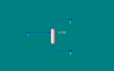
Vapor Liquid separation can be simulated in HYSYS using 2-phase separator. Following is an example with below feed gas at 32 barg @ -30 degC feeding a vapor liquid separator. Feed gas composition are N2 (0.38%), CO2 (0.68%), C1 (90.4%), C2 (4.1%), C3 (2.6%) and nC4 (1.84%), all in mole percent. Demister is provided in the vapor phase and maximum allowable pressure of 15 kPa is assumed. Those would like to understanding details of demister, read more in "Quick Understanding & Estimation of Mist Eliminator in Gas-Liquid Separator".
Why liquid in Vapor outlet ?
Above has been simulated HYSYS. It is pretty simple using 2-phase separator module in HYSYS. One of observation is the vapor outlet stream contains liquid. Vapor outlet from 2 phases separator should be in vapor phase. Why HYSYS predict present of liquid in vapor outlet ?
When pressure drop is allocated on the demister by entering pressure drop at "Vapour outlet", HYSYS view it as pressure drop on the vapor stream, outlet of 2-pases separator module. Vapor from separator is saturated vapor and pressure drop on the saturated vapor would result condensation due to Joule-Thompson (JT) effect. A liquid generated will be carried into the Vapor stream.
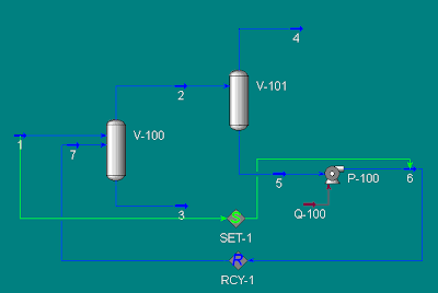
How to properly simulate a separator ?
In real separation, liquid generated in the demister (due to JT effect) will coalesce, formed larger droplet, trap by demister, droplet is separated from vapor leaving the separator and drop into liquid phase by gravity force. Thus, above straight forward simulation does not really represent a true separation. A proper simulation may include a "dummy separator" with zero pressure drop, downstream of the vapor outlet (2 phases). Separated liquid is mixed with feed stream using a "dummy pump". With this method, the vapor outlet from "dummy separator" will represent the true vapor from the separator. In this method, the "dummy separator" represent the demister and "dummy pump" represent the gravity form.
Above is just a simple trick for simulation and many may ignore it or do not even aware of this phenomenon. However, it is pretty important in presenting a true & correct Heat & Material Balance.
Related Topic
- Quick Understanding & Estimation of Mist Eliminator in Gas-Liquid Separator
- AMISTCO (P2) - Extensive info on Mist eliminator, knitted mesh, random & structured packing, distillation
- AMISTCO (P1) - Extensive info on Mist eliminator, knitted mesh, random & structured packing, distillation
- KnitMesh...Good Articles on Mist eliminator still available FREE...
- ACS - Design manual for Mist Eliminators, Trays, Packing, Internals...All in distillation columns
Labels: HYSYS, Separation
Tuesday, January 22, 2008

There are many young design engineer will experience or has experienced gas - liquid separator sizing. In most cases, a mist eliminator is used to trap small liquid droplet entrained in the gas. Now the engineer may experience difficulties in answering the following questions :
- What type of mist eliminator (e.g. mesh pads, vane pack, etc) should be used ?
- What are the advantages and disadvantages of mesh pad and vane pack ?
- How mesh pads and vane pack trap liquid droplet ?
- What is the liquid capture efficiency of mesh pad and vane pack ?
- How droplet size, mesh strand diameter, gas velocity, liquid density, gas density, gas viscosity, mesh pad/vane pack design affecting liquid capture efficiency ?
- What is the limit of mesh pad compare to vane pack ?
- How do i size mesh pad or vane pack mist eliminator ?
- What are the geometry and installation requirement of separator with mist eliminator ?
- ...etc
Although this article may assist you in determining the type of mist eliminator, dimension, mist eliminator thickness, gas flow area, etc using a recommended design Souders-Brown vapor load factor (K), however there are still many other type of mist eliminator (MistFix insertion mist eliminator, double-pocket vane pack, which potentially result better removal efficiency and cost effective as compare to ordinary mesh pads and vane pack. In addition, the graph is tested with air-water mixture, it may have some deviation with actual process fluid. The deviation could be insignificant or very significant.
You may use above proposed method for PRELIMINARY sizing in order to get a quick separator dimensioning, the detail selection and calculation shall be conducted by mist eliminator supplier with their proprietary graph and correction parameters.
In many real world examples, the mist eliminator thickness would be in the range of 4"-6". Thus, you may use this PRELIMINARY thickness in quick separator dimensioning.
Related Topic
- AMISTCO (P2) - Extensive info on Mist eliminator, knitted mesh, random & structured packing, distillation
- AMISTCO (P1) - Extensive info on Mist eliminator, knitted mesh, random & structured packing, distillation
- KnitMesh...Good Articles on Mist eliminator still available FREE...
- ACS - Design manual for Mist Eliminators, Trays, Packing, Internals...All in distillation columns
Labels: Mist Eliminator, Separation, Separator
Sunday, November 11, 2007
Johnson Matthey Catalyst (JMC) and Dialog have organized The 2nd Mercury Technical Seminar in Pattaya, Thailand after their success story in the 1st Mercury Technical Seminar, 2005. The seminar covers paper presentation on the first day and demonstration of catalyst loading and unloading processes on second day.
There are about 206 participants mainly from oil and gas field such as PTTEP, Chevron, Technip, ConocoPhilips, Petronas, etc have attended this event. Experts from JMC, Intertek, C-Chec, Peco, Chevron and Mercury Technology Services have presented few papers. The papers include :
- Overview of mercury in Oil & Gas and its development
- Mercury removal technologies overview
- Pre & Post treatment - Filtration
- Protecting Petrochemical Plant from Mercury
- Mercury Sampling & Testing
- New technology – Mercury removal in liquid hydrocarbon
- Research & Development – future technologies
There are number of interesting points that I managed to capture which I think is rather important and crucial.
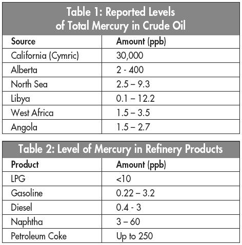
The following table presented mercury level for several crude & refinery product :
Present of mercury has reduced the crude / condensate price. JMC has developed and marketed it mercury removal in liquid hydrocarbon unit. Removal of mercury in liquid will definitely benefit the crude and condensate exporter by increasing the unit price.
ii) Intertek has conducted research in sampling and testing. They found that, mercury potentially adsorbed on the sampling bottle (glass) which may not be removed by simple solution rinsing. It needs to be extracted. The quantity of mercury shall be the tested medium reading plus extracted reading. This implies that those past laboratory testing results are under estimated the actual mercury content and shall be UPDATED.
iii) Second finding shown by Intertek is several samples collected at the same period from same sampling location showing different adsorption rate at the glass collection pot. This has created problem in bench marking mercury adsorbed on the glass pot. Intertek has used Teflon lined sampling pot which has more-less adsorbed mercury level.
iv) JMC has some break-through in mercury removal in aqueous system i.e. produced water and it is expected to be launched in the market next year. This no doubt is an great news to main oil and gas producer as there are having difficulties in disposing the produced and condensed water which contaminated with mercury.
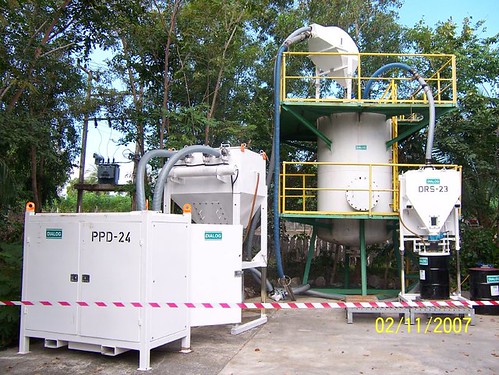
The second day was the demonstration of catalyst loading and unloading process. See below image for the entire system.
The following video clip shows catalyst LOADING process. (Click to view)
The following video clip shows catalyst UNLOADING process. (Click to view)
Further Reading :
i) In the past, there are a lot of success story in removal of mercury in Gas phase. Examples are Mercury removal unit (MRU) in Bongkot North, Pailin, Arthit field, etc. However, mercury removal in condensate (liquid hydrocarbon) and produced water are still yet to be developed. Generally the mercury will be send together with condensate and crude to onshore refinery for further treatment. This has reduced the crude / condensate price.
The following table presented mercury level for several crude & refinery product :
Present of mercury has reduced the crude / condensate price. JMC has developed and marketed it mercury removal in liquid hydrocarbon unit. Removal of mercury in liquid will definitely benefit the crude and condensate exporter by increasing the unit price.
ii) Intertek has conducted research in sampling and testing. They found that, mercury potentially adsorbed on the sampling bottle (glass) which may not be removed by simple solution rinsing. It needs to be extracted. The quantity of mercury shall be the tested medium reading plus extracted reading. This implies that those past laboratory testing results are under estimated the actual mercury content and shall be UPDATED.
iii) Second finding shown by Intertek is several samples collected at the same period from same sampling location showing different adsorption rate at the glass collection pot. This has created problem in bench marking mercury adsorbed on the glass pot. Intertek has used Teflon lined sampling pot which has more-less adsorbed mercury level.
iv) JMC has some break-through in mercury removal in aqueous system i.e. produced water and it is expected to be launched in the market next year. This no doubt is an great news to main oil and gas producer as there are having difficulties in disposing the produced and condensed water which contaminated with mercury.
The second day was the demonstration of catalyst loading and unloading process. See below image for the entire system.
The following video clip shows catalyst LOADING process. (Click to view)
The following video clip shows catalyst UNLOADING process. (Click to view)
This seminar has provided me with market updates, new findings & technologies related to mercury removal, knowledge improvements, etc as well as some hands-on experience. You are encourage to participate in next Mercury Technical Seminar which probably will be held on 2009.
Labels: Mercury, Separation
Friday, May 18, 2007
[CONTINUE...]
Technical Bulletins (Amistco)
WebWorm
Labels: Column, Design, Distillation, Mist Eliminator, Packed Column, Packing, Separation, Souders-Brown, Tower internals
Thursday, May 17, 2007
AMISTCO has published several good articles for Mesh and Vane Mist Eliminators from fundamentals, application, and design aspects.
WebWorm
Labels: Column, Design, Distillation, Mist Eliminator, Packed Column, Packing, Separation, Souders-Brown, Tower internals
