Sunday, May 23, 2010
Anyone can tell me what will be the set pressure for the spare PSV in the multiple PSV (3 X 50%) arrangement. ? Set pressure for 1st PSV is preset at 100% whilst set pressure for 2nd PSV is 105% of 1st PSV set pressure. Should we set 3rd PSV (spare) at 100% or 105% of 1st PSV set pressure ???
Considering a PSV systems with
- PSV-1 set at 100% set pressure
- PSV-2 set at 105% set pressure
- PSV-3 is spare for PSV-1 or PSV-2.
IF PSV-3 set at 100% set pressure
i) whenever PSV-1 is removed for inspection / maintenance, PSV-3 will be put in service. Then the situation will be - PSV-1 out of service
- PSV-2 set at 105% set pressure
- PSV-3 set at 100% set pressure
ii) whenever PSV-2 is removed for inspection / maintenance, PSV-3 will be put in service. Then the situation will be
- PSV-1 set at 100% set pressure
- PSV-2 out of service
- PSV-3 set at 100% set pressure
IF PSV-3 set at 105% set pressure
i) whenever PSV-1 is removed for inspection / maintenance, PSV-3 will be put in service. Then the situation will be- PSV-1 out of service
- PSV-2 set at 105% set pressure
- PSV-3 set at 105% set pressure
ii) whenever PSV-2 is removed for inspection / maintenance, PSV-3 will be put in service. Then the situation will be
- PSV-1 set at 100% set pressure
- PSV-2 out of service
- PSV-3 set at 105% set pressure
Recommended :
Subscribes to FREE Hydrocarbon Processing

RECOMMENDATION
Therefore setting spare PSV other than 100% of set pressure will possibly lead to situation where the initial relieving pressure higher than 100% of set pressure. This is against code requirement and therefore the spare PSV is recommended set at 100% of set pressure.
Related Topics
- Suspicious Discrepancy In Supercritical Fluid Relieving Calculation
- Tedious & Simple Method In Determining Specific volume For Isentropic Nozzle Flow Mass Flux
- Constant Density To Obtain Relieving Condition
- Discussion on ISENTROPIC and ISENTHALPIC process via Relief Valve
- API Std 520 Part 1 Dec 2008 is Released
- API Std 521 ADDENDUM, MAY 2008 - Check Out Revised Section
- Requirement of overpressure protection devices on system design to PIPING code
Labels: Overpressure Protection, Pressure Relief Device
Pressure Relief load estimation is commonly estimated by taking system is approximately at "steady state condition". The estimated relief load could be excessive due to conservative assumption, unrealistic external energy inputs, etc. Current trend is to utilize Dynamic simulation in order to derive realistic but still preserve conservatism, integrity and safety of plant pressure relief and overpressure protection systems. This approach inline with API std 521 recommendation and probably the way to go in near future.
Subscribes to FREE Hydrocarbon Processing
This study presented the dynamic simulation of a gas compression system, proving the viability of operational philosophy and emergency shutdown logic with quantitative process responses in various situations. To avoid unnecessarily high peak in an initial stage of blowdown, this study employed the controlled blowdown and investigated its safety level.
This study concluded that dynamic simulation of start-up and emergency operation improved the operability of the whole process. The revealed transient behavior demonstrated that PSVs sized to API standard led to chattering because the standard gives excessive size. Choice of properly sized PSVs eliminated the chattering with a decrease in relief loads by 40%. The blowdown valves and PSVs are likely to be oversized if the API RP 521 is observed. The dynamic simulation gave precise estimates, consequently decreased the flare loads, and better safety. The controlled blowdown system mitigated the flare load to about 60% of the conventional blowdown system. Its safety was more reliable than that of the conventional, satisfying SIL 2 of IEC 61508.
- Suspicious Discrepancy In Supercritical Fluid Relieving Calculation
- Tedious & Simple Method In Determining Specific volume For Isentropic Nozzle Flow Mass Flux
- Constant Density To Obtain Relieving Condition
- Discussion on ISENTROPIC and ISENTHALPIC process via Relief Valve
- API Std 520 Part 1 Dec 2008 is Released
- API Std 521 ADDENDUM, MAY 2008 - Check Out Revised Section
- Requirement of overpressure protection devices on system design to PIPING code
Labels: Dynamic, Overpressure Protection, Pressure Relief Device
Sunday, May 16, 2010
Earlier post “Seawater Treatment & Injection For Well Maintenance & Increase Productivity” discussed about the water source and its associated water injection treatment. Seawater will be filtered with coarse and fine filters to remove particles smaller than 2 micron with 98% removal efficiency. Filtered seawater will be deaerated to bring the Oxygen concentration down to 20 ppb. Oxygen scavenger is then injected to further reduce the Oxygen concentration down to 10 ppb in order to reduce corrosion to cost effective level. Chlorine is injected to injection water to avoid bacteria and alga growth.
Residue Oxygen in injection may still result corrosion in the pipeline. How much it affect the corrosion of Carbon steel pipeline ? Present of Chlorine is known further increase corrosivity of injection water. How this impact the corrosion water ? Increase of water velocity in pipeline will increase flow induced erosion of pipeline. Simultaneous erosion (flow induced) - corrosion (Oxygen & Chlorine) present in the pipeline. How water velocity affect corrosion ? What is the water velocity limit ? This post will present a water velocity limit with varies of oxygen concentration (and Chlorine content) in water .
Oxygen corrosion in water injection pipeline is controlled by diffusion rate of Oxygen into Cathodic with following reaction :

Steel is corroded on the Anodic side with following reaction :

Water Injection Velocity Limit
Chlorine Free
water injection velocity limit (Vmax)of Carbon steel pipeline is :

With Chlorine concentration of 0.5 ppm
water injection velocity limit (Vmax)of Carbon steel pipeline is :

CA = Corrosion Allowance (mm)
Y = Life span (years)
CO2 = Oxegen concentration (ppb)
T = Seawater temperature (degC)
ρw = Seawater density (kg/m3)
Example
Refer following figures for water injection velocity limit (m/s) versus oxygen level (ppb) with Chlorine free and 0.5 ppm Chlorine.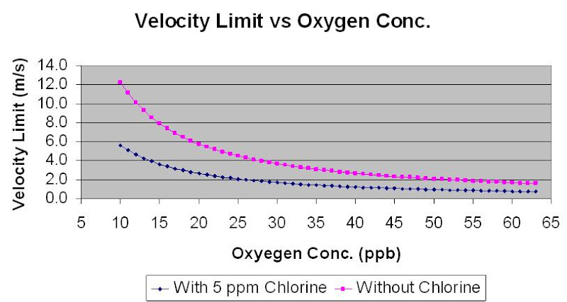
Above figures was based on
Corrosion Allowance, CA = 3.0mm
Life span (years), Y = 20 years
Seawater temperature, T = 25 degC
Seawater density, ρw = 1030 kg/m3
At 20 ppb of Oxygen concentration, the velocity limit is 5.7 m/s (Chlorine free) and 2.6 m/s (Chlorine = 0.5 ppm).
At 10 ppb of Oxygen concentration, the velocity limit is 12.2 m/s (Chlorine free) and 5.6 m/s (Chlorine = 0.5 ppm).
Ref :
1) J.W. Oldfiedl, G.L. Swales, B.Todd, “ Corrosion of Metals in Deaerated Seawater”, Proc. Of the 2nd Corrosion Conference, held Jan, 1981
2) J.M. Drugli, T. Rogne, “ Effect of Oxygen and Chlorine Content on the Corrosion Rate of Carbon Steel Welds in Injection Water” CORROSION/93 paper no 65
3) Mamdouh M. Salama, “Erosion Velocity Limits for Water Injection Systems”, 1993
Related Topics
- Seawater Treatment & Injection For Well Maintenance & Increase Productivity
- Chloride Stress Corrosion Cracking & Use correct MOC for seawater service
- How a Chloride Stress Corrosion Cracking Lookslike ?
- Crevice Corrosion Engineering Guide Software for Stainless Steels
- Different Equation for Pitting Resistance Equivalent Number (PREN)
- Guideline on Use of MR0175 / ISO15156
Labels: Chloride Stress Corrosion Cracking, Oil and Gas
Indian Chemical Industry is one of the oldest industry in India. It plays crucial role & contributes significantly towards industrial and economical growth of the nation.
- Petrochemicals :- The biggest and fastest growing sector
- Inorganic Chemicals :- Has a stiff competition with international market
- Organic Chemicals :- Mostly located in western part of India
- Fine and specialties :- Highly fragmented, operate on low volume high margin basis
- Bulk Drugs :- Mainly Indian companies, Formulations are primarily MNC’s
- Agrochemicals :- Growth rate is 10% per annum
- Paints and Dyes :- Growth rate 12% and market is highly fragmented
Until 1991, India had a closed economy and chemical manufacturing was largely controlled by licensing regulations. Indian chemical industry has evolved over the years into producing high quality and reasonably priced products. Indian chemicals and chemical-based products are exported all over the world. Intensive efforts in the areas of research and development have resulted in development of technologically sound, environmentally confirming and economically viable products by the chemical industry in India.
Across the world, the chemicals industry is undergoing the process of globalization, consolidation, product innovation and cost rationalization. This has resulted in a steady shift of manufacturing from western countries to Asia-mainly India, China and West Asia. Due to this there is an increase in the domestic chemical production and exports, with increasing foreign investment.
Indian chemical industry possesses a well-built and diversified base with its operations in many areas such as pharmaceuticals, insecticides and pesticides, and paints. The growth rate of this industry is comparatively higher than all other manufacturing sectors in India. This industry is labor-intensive and therefore human resource is a vital aspect of this industry.
GLOBAL SCENARIO
Global chemical market is approximately USD 1700 bn. The area wise breakup is given below. Global chemical industry growth rate is 2-3%
Country - USD Bn (year 2007)
*************************
Western Europe - 731
N. America - 374
S. America - 68
Asia - 442
Rest - 85*************************
Total - 1698
*************************
Western Europe - 731
N. America - 374
S. America - 68
Asia - 442
Rest - 85*************************
Total - 1698
Huge investments are taking place in China and the Middle East. Our major competitors are China, Taiwan, Korea and the Gulf while major export markets are EU and USA.
Year - US BillionINDIAN SCENARIO
Market size of indian chemical industry is given below*************************
2006 - 30
2010 - 70
2015 - 100+ (expected)
*************************
Indian chemical industry has a share of 14% in indian industry and is the largest single industry segment. 80% of India’s chemical industry is located at Gujrat and indian chemical industry is growing at the rate of 12 -13% per annum.
The industry serves the basic need of many different industry verticals like natural gas, water, oil, metals, minerals, air, oil, etc and all these verticals eventually bring into marketplace an array of products, almost 70000. Although domestic performance is well, Indian chemical industry has to face stiff competition in international market
The strengths of Indian Chemical Industry
- Long private sector history in textile chemicals, colourants, leather chemicals, et
- It is aggressively competitive overseas
- Scope to grow for indian market (per capita consumption is very low)
- Large pool of skilled manpower is available
- English is commonly spoken language
- Intellectual Property Right enhance the confidence of investors
- Aggressive cost management and use of knowledge engineering
- Joint venture possible
- Contract manufacturing / research possible
- Consolidation and integration
- Outsourcing of services possible
- Product and application development possible
- Chemical Science in China and India is strong in Polymer, Organic Chemistry and Process Engineering
The spread of chemical industry is as follows: Private Limited Company 69%, Public Limited Company 12%, Partnership 11%, Propriyory 08%.
Problems faced by Indian Chemicals Industry
- Lack of scale
- Huge investment and long gestation
- Major threats are from Korea, Taiwan, China and Gulf
- Mindset is largely for trading and not partnering
- Absence of Infrastructure
- Fluctuating prices of crude oil
- Scarcity of capital
- Low investment in R&D.(32nd rank )
- High taxation
- High capital , raw materials and utility cost , hence less competitive
- Highly fragmented
- Presence of many MNC
*****************************************
Guess post by P.J. Lakhapate
P.J. Lakhapate is a Chemical Engineer from UDCT, Mumbai (1975) & has completed a Post Graduation in systems management from J. Bajaj Institute, Mumbai. He is a lead assessor for ISO-9000. He received Quality Award from Chemtex Engg of India Ltd,Powai. He has travelled U.S.A., Brazil, Russia, Kuwait, Saudi Arabia. He has written more than 40 articles & published in national & international magazines. He is distinguished member of expert committee group (for PUMPS & VALVES ) of NATIONAL ADVISORY COUNCIL. He has to his credit a work experience of more than 35 years. He is working as a consultant.
Email : plakhapate@rediffmail.com
Thanks to P.J. Lakhapate.
by JoeWong
*****************************************
Related Topic
Labels: Process Intensification, Process simulation
Process Intensification (PI) is a revolutionary approach to process and plant design, development and implementation. It presents significant scientific challenges to chemists, biologists and chemical engineers while developing innovative systems and practices which can offer drastic reduction in chemical and energy consumptions, improvements in process safety, decreased equipment volume and waste formation and increased conversions and selectivity towards desired product(s). In addition they can offer relatively cheaper and sustainable process option.
Here one must note that development of a new chemical route or a change in composition of a catalyst, no matter how dramatic the improvements they bring to existing technology, do not qualify as process intensification.
- Process Intensifying Equipment
- Process Intensifying Methods (Unit Operations)
Process Intensifying Equipment
 Monolythic Catalytic Reactor
Monolithic substrate used today for catalytic applications are metallic or non metallic bodies providing a multitude of straight narrow channels of defined uniform cross sectional shapes To ensure sufficient porosity and enhance the catalytically active surface, the inner walls of the monolith channels usually are covered with a thin layer of wash coat, which acts as the support for the catalytically active species.
The advantages of Monolithic Reactors are as follow.
- Low pressure drop
- High mass transfer area
- Low space requirement
- Low cost
- Better Selectivity
- Better Safety
- Less Environmental problems
 Micro-Reactors
Micro-reactors are chemical reactors of extremely small dimensions that usually have a sandwich-like structure consisting of a number of slices (layers) with micro-machined channels (10-100 micron in dia.). The layers perform various functions, from mixing to catalytic reaction, heat exchange, or separation
Higher values of heat transfer coefficient values upto 20000 W/m2K are reported. Hence highly exothermic reactions can be easily carried out .This is very useful for toxic or explosive reactants / products. The chan¬nels in the plates of micro-channel heat exchangers are usually around 1 mm or less wide, and are fabricated via silicon micromachining, deep X-ray lithography, or non-lithographic micromachining
 Spinning Disk Reactors (SDR)
For fast and very fast liquid-liquid reactions like sulphonation, nitration , polymerization (styrene) involving high heat of reactions, this type of reactor is developed by Newcastle University. In SDRs, a very thin (typically 100 micron) layer of liquid moves on the surface of a disk spinning at up to approximately 1,000 rpm. At very short residence times (typically 0.1 s), heat is efficiently removed from the reacting liquid at heat-transfer rates reaching 10,000 W/m2K. SDRs currently are being commercialized.

Static Mixer Reactors
Static Mixers are not only used for physical mixing of Gas-Gas, Liquid –Liquid and Gas –Liquid applications but used in reactions also. Use of structured packing reduce the pressure drop considerably. When static mixers are placed in heat exchanger tubes better mixing as well as heat transfer can be achieved. A Norwegian company has intensified manufacturing of Hydrogen Peroxide by using static mixers extensively to combine oxidation and extraction.
Supersonic Gas-Liquid Reactor
Praxair Inc. developed this type of reactor for fast and very fast processes for gas/liquid systems and it employs a supersonic shockwave to disperse gas into very tiny bubbles in a supersonic in-line mixing device.
Recommended :
Subscribes to FREE Hydrocarbon Processing
The Jet Impingement Reactor
An apparatus to allow reaction in liquid phase. The apparatus is a vessel having a baffle. There are openings in the baffle through each of which liquid passes as jet. Neighboring openings are sufficiently close to allow impingement of the jet thereby allowing for the reaction of liquids. This is useful for immiscible liquids. e.g. Nitration of aromatic compound with aqueous solution , manufacture of Nitroglycerine etc.
NORAM Engineering and Constructors (Vancouver, BC) uses this system of specially configured jets and baffles to divide and remix liquid streams with high intensity.

Buss Loop ReactorSubscribes to FREE Hydrocarbon Processing
The Jet Impingement ReactorAn apparatus to allow reaction in liquid phase. The apparatus is a vessel having a baffle. There are openings in the baffle through each of which liquid passes as jet. Neighboring openings are sufficiently close to allow impingement of the jet thereby allowing for the reaction of liquids. This is useful for immiscible liquids. e.g. Nitration of aromatic compound with aqueous solution , manufacture of Nitroglycerine etc.
NORAM Engineering and Constructors (Vancouver, BC) uses this system of specially configured jets and baffles to divide and remix liquid streams with high intensity.
This type of reactor is suitable for gas – liquid system and can be used for Amination, Alkylation, Carbonylation, Chlorination, Ethoxylation, Hydrogenation, Nitrilation, Oxidation , Phosgenation etc. The Buss loop reactor has been successfully used for hydrogenation, amination and sulphonation.
Rotary Pump Reactor
Rotor/stator mixers, which are aimed at processes requiring very fast mixing on a micro scale, contain a high-speed rotor spinning close to a motionless stator. Fluid passes through the region where rotor and stator interact and experiences highly pulsating flow and shear. In-line rotor/stator mixers resemble centrifugal pumps and, therefore, may simultaneously contribute to pumping the liquids.
HIGEE Reactors / Separations / Stripper
HIGEE technology intensifies mass-transfer operations by carrying them out in rotating packed beds in which high centrifugal forces (typically 1,000 g) occur. This way, heat and momentum transfer as well as mass transfer can be intensified. The rotating-bed equipment can be used in absorption, extraction, distillation and also can be utilized for reacting systems (especially, those that are mass-transfer limited). It potentially can be applied to other phase combinations including three-phase gas/liquid/solid systems. e.g. Absorption of CO2, H2S using Di-ethanol Amine
Another example is the filtering centrifuge-cum-dryer. The centrifuge combines these operations for a pesticide/herbicide/pharmaceutical product with recycle of the solvent used for crystallization. This saves on floor area, operators, conveying, drying equipment, etc. Centrifuge for liquid- liquid separation are already in use.
HIGEE packed bed replaces towers up to 50-60 ft tall and can process up to 250 tons of water per hour. The size of the equipment is about 6 ft tall.. The deoxygenated water is required for oil well injection to enhance oil well production. This could also be used for boiler water deaeration Dow Chemicals have used these columns for stripping of hypochlorous acid from brines
LOGEE Concept
Lower value of g will affect the convection currents. This in turn may affect growth of the crystals in crystallization. Lowering effect of g can be obtained by providing bottom entry in the crystallization vessel.
Compact Heat Exchangers Reactors
Plate Heat Exchangers, Spiral Plate Heat Exchangers, Capillary Tube Type Shell and Tube type heat exchangers are already used as reactors .
There are several other type of reactors such as Biofilm Annular Reactor , Oscillating Flow Reactors, Drip Flow reactor etc can be used to improve the performance
Process Intensifying Methods (Unit Operations)
Several Process Intensifying methods listed as follows :a) Multifunctional Reactors
b) Hybrid Separators
c) Alternative source of energy
d) Other methods
MULTIFUNCTIONAL REACTORS
Reverse Flow Reactor The reactor concept aims to achieve an indirect coupling of energy necessary for endothermic reactions and energy released by exothermic reactions, without mixing of the endothermic and exothermic reactants, in closed-loop reverse flow operation. Periodic gas flow reversal incorporates regenerative heat exchange inside the reactor. This reactor is used for SO2 oxidation, total oxidation of hydrocarbons in off-gases, and NOx reduction.
Reactive Distillation
It is a distillation column filled with catalytically active packing. In the column, chemicals are converted on the catalyst while reaction products are continuously separated by fractionation (thus overcoming equilibrium limitations). The catalyst used for reactive distillation usually is incorporated into a fiberglass and wire-mesh sup¬porting structure, which also provides liquid redistribution and disengagement of vapor. Structured catalysts, such as Sulzer's KATAPAK,
The advantages of catalytic distillation units, besides the continuous removal of reaction products and higher yields due to the equilibrium shift, consist mainly of reduced energy requirements and lower capital investment The number of processes in which reactive distillation has been implemented on a commercial scale is still quite limited - but the potential of this technique definitely goes far beyond today's applications.
Membrane Reactor
The membrane enable in-situ separation of catalyst particles from reaction products. thus itself becoming a highly selective reaction-separator It also can be applied for a controlled distributed feed of some of the reacting species, either to increase overall yield or selectivity of a process (e.g., in fixed-bed or fluidized-bed membrane reactors or to facilitate mass transfer (e.g., direct bubble-free oxygen sup¬ply or dissolution in the liquid phase via hollow-fiber membranes ).
Heat- and mass-integrated combination of hydrogenation and dehydrogenation processes can be carried out in a single membrane unit. Yet, practically no large-scale industrial applications have been reported so far due to high price
Catalytic Reactors
Reactive extruders used in the polymer industries enable reactive processing of highly viscous materials without re¬quiring the large amounts of solvents. Popular twin-screw extrud¬ers offer effective mixing, can operate at high pres¬sures and temperatures, plug-flow characteristics, and capability of multi-staging. New types of extruders with catalyst immobilized on the surface of the screws may allow carrying out three-phase catalytic reactions.
Methyl Acetate
Eastman Chemicals successfully changed the methyl acetate plant. The process involves the esterification of methanol with acetic acid in presence of catalyst, removal of water of reaction, distillation of product and recovery and recycle of excess reactants. There are as many as six distillation columns that have been replaced by single multifunctional distillation column. Imagine the reduction of number of reboilers, condensers, pumps, etc. The heat input and rejection is practically only at two points.
Fuel CellHere, integration of chemical reaction and electric power generation takes place (Simultaneous gas/solid reaction and comminution in a multifunctional reactor also has been investigated).
Isothermal Reactor Process
Isothermal reactor crystallizer cooler operation gives higher P2O5 recovery efficiency, superior sulfate control. The P2O5 content of gypsum is 0.7%, phosphoric acid concentration 28%. This gigantic single vessel, combining, reactor, crystallizer and cooler, (12 meter dia, 1300 M3 volume) occupies less space, requires fewer moving parts and is substantially less expensive to build, operate, clean and maintain than conventional installations, thereby substantially reducing capital and operating costs.
HYBRID SEPARATION
Membrane Absorption and Stripping
Here the membrane serves as a permeable barrier between the gas and liquid phases. By using hollow-fiber membrane modules, large mass-transfer areas can be created,
Membrane Distillation
This offers operation independent of gas and liquid flow rates, without entrainment, flooding, channeling, or foaming The technique is widely considered as an alternative to reverse osmosis and evaporation. Membrane distillation basically consists of bringing a volatile component of a liquid feed stream through a porous membrane as a vapor and condensing it on the other side into a permeate liquid. Temperature difference is the driving force of the process. Main advantages of membrane distillation are
- 100% rejection of ions, macro-molecules, colloids, cells, and other non-volatiles;
- lower operating pressure ,hence lower risk and low equipment cost
- less membrane fouling, due to larger pore size;
- lower operating tem¬peratures en¬able processing of temperature-sensitive materials.
Here a selective adsorbent is added to a distillation mixture. This increases separation ability and may present an attractive option in the separation of azeotropes or close-boiling components. Adsorptive distillation can be used, for the removal of trace impurities in the manufacturing of fine chemicals; it may allow switching some fine-chemical processes from batch wise to continuous operation.
ALTERNATIVE FORMS AND SOURCE OF ENERGY
Ultrasound
Ultrasound is used as a source of energy for formation of micro- bubbles in the liquid medium of reaction. These cavities can be thought of as high energy micro-reactors. Their collapse creates micro-implosions with very high local energy release (temperature rises of up to 5,000 K and negative pressures of up to 10,000 atm are reported ). This may have various effects on the reacting species, from homolytic bond breakage with free radicals formation, to fragmentation of polymer chains by the shockwave in the liquid surrounding the collapsing bubble. This is still at development stage.
Solar Energy
A novel high-temperature reactor in which solar energy is absorbed by a cloud of reacting particles to supply heat directly to the reaction site has been studied. Experiments with two small-scale solar chemical reactors in which thermal reduction of MnO2 took place also are reported. Other studies describe, the cyclo-addition reaction of a carbonyl compound to an olefin carried out in a solar furnace reactor and oxidation of 4-chlorophenol in a solar-powered fiber-optic cable reactor.
Microwave
Microwave heating can make some organic syntheses proceed up to 1,240 times faster than by conventional techniques. Microwave heating also can enable energy-efficient in-situ desorption of hydrocarbons from zeolites used to remove volatile organic compounds.
Electric Field
Electric fields can augment process rates and control droplet size for a range of processes, including painting, coating, and crop spraying. In these processes, the electrically charged droplets exhibit much better adhesion properties. In boiling heat transfer, electric fields have been successfully used to control nucleation rates. Electric fields also can enhance processes involving liquid/liquid mixtures, in particular liquid/liquid extraction where rate enhancements of 200-300% have been reported.
Plasma Technology
Gliding Arc technology, that is, plasma generated by formation of gliding electric discharges. These discharges are produced between electrodes placed in fast gas flow, and offer a low-energy alternative for conventional high-energy-consumption high-temperature processes. Example include: methane transformation to acetylene and hydrogen, destruction of N2O, reforming of heavy petroleum residues, CO2 dissociation, activation of organic fibers, destruction of volatile organic compounds in air, natural gas conversion to synthesis gas, and SO2 reduction to elemental sulfur.
OTHER METHODS
Supercritical Fluid (SCF)
SCF is any substance at a temperature and pressure above its critical point. It can diffuse through solids like a gas, and dissolve materials like a liquid. In addition, close to the critical point, small changes in pressure or temperature result in large changes in density, allowing many properties of a supercritical fluid to be "fine-tuned".
Many of the physical and transport properties of a SCF are intermediate between those of a liquid and a gas. Diffusivity in an SCF, falls between that in a liquid and a gas; this suggests that reactions that are diffusion limited in the liquid phase could become faster in a SCF phase. Also Compounds that are largely insoluble in a fluid at ambient conditions can become soluble in the fluid at supercritical conditions. Conversely, some compounds that are soluble at ambient conditions can become less soluble at supercritical conditions. SCFs have been investigated for systems, including enzyme reactions, Diels-Alder reactions, organo-metallic reactions, heterogeneously catalyzed re¬actions, oxidations, and polymerizations.
Cryogenic Techniques
Cryogenic techniques involving distillation or distillation combined with adsorption, today are used almost exclusively for production of industrial gases, may in the future prove attractive for some specific separations in manufacturing bulk or fine chemicals.
Dynamic Reactor Operations
The inten¬tional pulsing of flows or concentra¬tions has led to a clear improvement of product yields or selectivities at lab scale. Yet, commercial-scale applications are scarce.
Continuous Processes
There are several examples in which continuous process is more economical than batch processes e.g
- Oxy chloride from Phosphorous Trichloride using air or oxygen
- Monobromo benzaldehyde required for Meta Phenoxy Benzaldehyde (Pesticide intermediate)

Vapour Absorption Refrigeration
This is a well known example where several equipment are put together to make compact ,energy efficient equipment.


Implementation of Process Intensification (PI)
May consider following actions for PI implementation.
P.J. Lakhapate is a Chemical Engineer from UDCT, Mumbai (1975) & has completed a Post Graduation in systems management from J. Bajaj Institute, Mumbai. He is a lead assessor for ISO-9000. He received Quality Award from Chemtex Engg of India Ltd,Powai. He has travelled U.S.A., Brazil, Russia, Kuwait, Saudi Arabia. He has written more than 40 articles & published in national & international magazines. He is distinguished member of expert committee group (for PUMPS & VALVES ) of NATIONAL ADVISORY COUNCIL. He has to his credit a work experience of more than 35 years. He is working as a consultant
Email : plakhapate@rediffmail.com
Thanks to P.J. Lakhapate.
by JoeWong
Advantages /benefits of Process Intensification
- Safety - As per Cell for Industrial Safety and Risk Analysis (CISRA) the major cause of accident is STORAGE. When size of the process equipment is reduced , operating inventory will be reduced.
- Health - The fugitive emissions will be reduced due to smaller equipment size. This will improve the health of the society in general. Environment Better efficiency /yield leads to less rejection to environment hence less pollution.
- Quality - It is possible to get desired quality of products
- Energy - Due to higher energy efficiency, leads to enhanced production
- Cost - Less due to less raw material, catalyst, labour, utility and space requirement


Implementation of Process Intensification (PI)
May consider following actions for PI implementation.
- Utilise existing facilities / human resources efficiently
- Develop new modern facilities
- Connect all scientific research institutes
- Allocate separate funds for R&D
- Provide favorable environment for R&D
- Develop platform for Industry –Academy interaction
- Develop patent laws in accordance with global practices.
- Create awareness
- Provide incentives in the form of awards
*****************************************
Guess post by P.J. Lakhapate
P.J. Lakhapate is a Chemical Engineer from UDCT, Mumbai (1975) & has completed a Post Graduation in systems management from J. Bajaj Institute, Mumbai. He is a lead assessor for ISO-9000. He received Quality Award from Chemtex Engg of India Ltd,Powai. He has travelled U.S.A., Brazil, Russia, Kuwait, Saudi Arabia. He has written more than 40 articles & published in national & international magazines. He is distinguished member of expert committee group (for PUMPS & VALVES ) of NATIONAL ADVISORY COUNCIL. He has to his credit a work experience of more than 35 years. He is working as a consultant
Email : plakhapate@rediffmail.com
Thanks to P.J. Lakhapate.
by JoeWong
*****************************************
Related Topic- ASPEN PIPESYS MANUAL
- Useful Documentation for AFSA / FLARENET...
- Useful Documentation for UNISIM...
- Useful Documentation for HYSYS ...
Labels: Process Intensification, Process simulation
The basic principle of the Combined Cycle is by burning gas in a gas turbine (GT) produces electric power by a coupled generator and routing hot exhaust gases through a water-cooled heat exchanger produces steam, which can be turned into electric power with a coupled steam turbine and generator.

Recommended :
Subscribes to FREE Hydrocarbon Processing
This set-up of Gas Turbine, waste-heat boiler, steam turbine and generators is called a combined cycle. This type of power plant is being installed in increasing numbers round the world where there is access to substantial quantities of natural gas. This type of power plant produces high power outputs at high efficiencies and with low emissions. It is also possible to use the steam from the boiler for heating purposes so such power plants can operate to deliver electricity alone
Subscribes to FREE Hydrocarbon Processing
This set-up of Gas Turbine, waste-heat boiler, steam turbine and generators is called a combined cycle. This type of power plant is being installed in increasing numbers round the world where there is access to substantial quantities of natural gas. This type of power plant produces high power outputs at high efficiencies and with low emissions. It is also possible to use the steam from the boiler for heating purposes so such power plants can operate to deliver electricity aloneEfficiencies are very wide ranging depending on the lay-out and size of the installation and vary from about 40-56% for large new natural gas- fired stations. Developments needed for this type of energy conversion is only for the gas turbine. Both waste heat boilers and steam turbines are in common use and well-developed, without specific needs for further improvement.
The primal objective of this report is to show the efficiency into simulate a Gas Power Plant with Combined Cycle technology with HYSYS software; and to optimize the process to get the biggest possible economic benefit, making changes in the feed variables of the combined cycle plant. The data of this project are based on the document of the Department of Energy of United States.
Read more in "Simulation of Gas Power Plant"
Download
Related Topics
Related Topics
- HYSYS Simulation of MEA Based CO2 Removal
- Correct model and thermo package in Amine system simulation using HYSYS
- Incompatibility HYSYS Version & Its File...What to do ?
- Adjusted Method For Compressor Settle Out (with Vapor & Liquid) Using HYSYS
- Simple Method For Compressor Settle Out (Vapor Only) Using HYSYS
- HYSYS related
Labels: HYSYS, Power, Process simulation
Monday, May 10, 2010

- Rigorously model single phase and multiphase flows
- Perform forward and reverse pressure calculations
- Determine changes in pipeline flow or conditions and their effect on an entire plant using a Aspen HYSYS simulation
- Compute detailed pressure and temperature profiles for pipelines that traverse irregular terrain, both onshore and offshore
- Perform special analysis including pigging slug size predictions, erosion velocity limits, and the likelihood of severe slugging in vertical or near-vertical risers
Perform sensitivity calculations to determine the dependency of system behavior on any parameter
Determine the possibility of increasing capacity in existing pipelines based on computational effects, pipeline effects, and environmental effects
ASPEN PIPESYS 2002 Getting Started
ASPEN PIPESYS 2003 Installation Guide
ASPEN PIPESYS 2003 Tutorials
ASPEN PIPESYS 2003 User Guide
ASPEN PIPESYS 2004.1 Getting Started
ASPEN PIPESYS V7 Getting Started
If you found any documents related to ASPEN PIPESYS and/or available FREE for all, you are encourage to share within our community. You may drop a note via email or comment. Please include your nickname.
Related Topic
Related Topic
Labels: HYSYS, Piping, Process simulation
Sunday, May 9, 2010
Water injection is common applied in maintaining crude reservoir to increase crude productivity. For offshore facilities, seawater is commonly lifted and treated for water injection purpose. The water injection rate is subject to reservoir condition and crude production. Particle present in seawater potentially results formation blockage and reduce injectivity. Oxygen present in seawater potentially results severe corrosion of transfer pipeline and injection tubing. Alga and bacteria present in seawater may potentially growth result corrosion and formation blockage. Therefore seawater use for injection shall be treated prior transfer and injection.
Seawater Treatment
Seawater used for water injection will goes through a series of treatments :- Filtration - remove particles
- Deaeration - remove oxygen
- Chemical injection - prevent foaming, corrosion, alga / bacteria growth
Seawater lifted will pass through filtration package. The filtration package commonly consist of two levels of filtration. First level filtration is also known as Coarse Filtration where the filter is provided to remove particle with size larger than 80-100 micron. The common required removal efficiency is 98%. The filter is normally equipped with auto-backwash facilities e.g. rotational backwash motor. Second level filtration is also known as Fine Filtration where the filter is provided to remove particle with size large than 2 micron with removal efficiency of 98%. Similarly this filter is equipped with auto-backwash facilities with the assistance of blower.
Deaeration
Seawater is aerated in ambient contains high oxygen contents. Typically the seawater is considered saturated with oxygen and this quantity is sufficient to results significant corrosion in transfer pipeline and injection tubing. Corrosion is increased with increased in quantity of oxygen in seawater. The oxygen level in the seawater is commonly deaearated down to 20-40 ppb in the deaeration column. Oxygen scavenger is injected downstream of deaeration column to further bring the oxygen level down to 10-20 ppb. Two main methods are used for deaeration :
- Vacuum deaeration
- Gas stripping
Chemical injection
CoagulantPresent of large quantity of small particle may results particle passing filtration, accumulates, agglomerate and finally results plugging of formation. Coagulant may be required to be injected upstream of filtration package to promote particle coagulation and filtration.
Anti-Foam
Seawater may be contaminated with hydrocarbon when it is lifted. Seawater used for processing cooling, any leakage in the seawater heat exchanger also result Hydrocarbon present in the seawater. Presented of hydrocarbon in seawater may results foaming in deaeration column. Therefore, anti-foam may be required to suppress foaming.
Biocide (Hypo-chloride)
Bacteria presents in seawater may results corrosion and alga growth which release solid waste to promote formation plugging. Hypo-Chloride is injected to prevent bacteria and alga growth. One shall take note present Chlorine is seawater may also results corrosion. Concentration subject to type of Biocide, however 5 ppm level could be good guess.
Corrosion Inhibitor
Present of Chlorine, residue bacteria and residue oxygen promote corrosion. Therefore corrosion inhibitor (CI) is injected to prevent / minimize corrosion. Concentration subject to type of CI, however 5 ppm level could be good guess.
Related Topics
- Chloride Stress Corrosion Cracking & Use correct MOC for seawater service
- How a Chloride Stress Corrosion Cracking Lookslike ?
- Crevice Corrosion Engineering Guide Software for Stainless Steels
- Different Equation for Pitting Resistance Equivalent Number (PREN)
- Guideline on Use of MR0175 / ISO15156
Labels: Chloride Stress Corrosion Cracking, Oil and Gas
The control of CO2 emission is becoming one of the most challenging environmental issues facing many countries today. Recent years has seen an increase in the reported use of process simulators to assess feasibility and design and troubleshoot of CO2 capture using amine solution. A simulation-optimization framework comprising of HYSYS simulator is presented and a jumping gene based multi-objective simulated annealing technique to evaluate the efficacy of CO2 removal using DEA solution. The novelty of this approach is that, both simulation and optimization of the process are performed simultaneously in an automated fashion to fully explore the trade-off surface of CO2 capture efficiency and operating cost.

The framework has been developed by integrating HYSYS simulator with a jumping gene based multi-objective simulated annealing technique and applied to CO2 capture process from a gas power plant. It has been shown to be capable of generating Pareto optimal solution involving CO2 capture efficiency and operating cost. Such Pareto set will form the basis for comparison with other amine technology. Future work include using other amine solutions as well as mixture of amines. Application to coal or fuel based power plant will also be part of future investigation.
DownloadRelated Topics
- Performance of Gas Sweetening with Mixture of DEA & MDEA
- HYSYS Simulation of MEA Based CO2 Removal
- Amines Type & Points Assist in Selection
- Several Concerns in High CO2 Field Development
- Correct model and thermo package in Amine system simulation using HYSYS
- Safety Moment with H2S
- What are the concerns related to H2S ?
- CO2 Related
Labels: Acid Gas Removal, CO2, Gas Sweethening
FREE Hydrocarbon Processing for MAY 2010 is available now...

Select Articles from the May Issue
Flow-induced fatigue failure in tubular heat exchangers
Case histories describe a variety of failures and solutions
Case histories describe a variety of failures and solutions
Purging and inerting large-volume tankage and equipment - jet mixing concept - Part 1
Here are the advantages and disadvantages of the various methods
Here are the advantages and disadvantages of the various methods
Heat-exchanger failure analysis in a naphtha cracking unit
This case history analyzed the failure and makes recommendations to prevent future failures
This case history analyzed the failure and makes recommendations to prevent future failures
Oil-mist lubrication for fin-fan shafts
Tests show it is superior to grease lubrication
Tests show it is superior to grease lubrication
Fundamental changes coming in Asia's petrochemical industry
Massive new processing additions will impact operations in this region as well as in the global market
Establishing safety representatives who are effective
Follow these protocols for a safer workplace
Consider CFD analysis to support critical separation operations
This modeling method can help eliminate chronic problems caused by feed mal-distribution and poorly designed feed devices
Strategize preshutdown work to enhance productivity
Adopt these principles from a refinery revamp project
Implementing a suitable safety instrumented system—Part 1
The analysis is the most important step for engineering and designing a suitable system
Sulfur Solutions 2010
Technological developments cost-effectively manage sulfur in various forms
Case 56: Quick troubleshooting of shaft failures
Some simple calculations can guide the way to improved performance
****************************
If you yet to be subscriber of Hydrocarbon Processing, requested your FREE subscription via this link (click HERE). Prior to fill-up the form, read "Tips on Succession in FREE Subscription".
Related Post
- Tips on Succession in FREE Subscription
- Most Important & FREE Magazines That I Read are in Softcopy
- Non - Technical Quick References for a Chemical & Process Engineers
- More You Share More You Learn
- Knowledge is Own by Everyone but Not Someone
Labels: E-Doc, Education, Learning
Tuesday, May 4, 2010
Methyldiethanolamine (MDEA), and Diethanolamine (DEA) have been used for CO2 & H2S removal in Gas sweetening unit. DEA is non-selective to CO2 and H2S. However, irreversible reactions of DEA with CO forming corrosive degradation products & increase corrosiveness. MDEA is highly selective to H2S with low corrosiveness. What is performance of mixtures of DEA and MDEA solutions in CO2 and H2S removal ?
In the present paper, the use of amine mixtures employing methyldiethanolamine (MDEA), and diethanolamine (DEA) have been investigated for a variety of cases using a ASPEN HYSYS process simulation. The simulation results show that,
- 40%MDEA with 10% DEA, 30% MDEA with 10 % DEA and 40% MDEA with 5% DEA were the best result in the absorption processes of CO2 from the natural gas.
- 30%MDEA with 10% DEA, 40%MDEA with 5 % DEA and 40%MDEA with 10 % DEA were the best result in the absorption processes of H2S from the natural gas comparing with other mixing amines.
- 20% MDEA with 10% DEA, 30% MDEA with 10 % DEA and the 40% MDEA with 10 % DEA have the lowers amount of H2S in the sweet gas comparing with different percent of DEA without mixing.
- The temperature of rich amine decrease with increase the circulation rate in all different percent of mixing amines and different percent of MDEA without mixing.
- The reboiler temperature was constant in the 20% MDEA with 10 % DEA and in the 30%MDEA, 40%MDEA and in the 50%MDEA, otherwise the reboiler temperature increase with increase the circulation rate in all different percent of mixing amines.
Related Topics
- HYSYS Simulation of MEA Based CO2 Removal
- Amines Type & Points Assist in Selection
- Several Concerns in High CO2 Field Development
- Correct model and thermo package in Amine system simulation using HYSYS
- Safety Moment with H2S
- What are the concerns related to H2S ?
- CO2 Related
Labels: Acid Gas Removal, CO2, Gas Sweethening
Monday, May 3, 2010
MEA (monoethanol amine) based CO2 removal process have been simulated with the ASPEN HYSYS process simulation tool with the Peng Robinson (PR) and Amines Property Package models which are available in Aspen HYSYS. The CO2 removal in % and the energy consumption in the CO2 removal plant are calculated as a function of amine circulation rate, absorption column height, absorption temperature and steam temperature.
Recommended :
Subscribes to FREE Hydrocarbon Processing
Selection of type of solvent is complicated and subject to many parameters such feed gas composition and condition, gas impurities specification, life cycle cost, space, salt deposition, byproduct, losses, hydrocarbon absorption, etc. Read more in "Amines Type & Points Assist in Selection".
Recommended :
Subscribes to FREE Hydrocarbon Processing
Selection of type of solvent is complicated and subject to many parameters such feed gas composition and condition, gas impurities specification, life cycle cost, space, salt deposition, byproduct, losses, hydrocarbon absorption, etc. Read more in "Amines Type & Points Assist in Selection".An absorption and desorption process for CO2 removal with an aqueous MEA solution has been simulated. The exhaust gas from the power plant model is used as the feed to this model. The absorption column is specified with 10 stages each with a Murphy efficiency of 0.25. An estimated HETP (Height Equivalent to a Theoretical plate) of 4 meter, is about equivalent to 0.25 efficiency for each meter of packing. Traditional concentrations, temperatures and pressures are used in the base case simulation. The thermodynamics for this mixture is described by an Amines Property Package available in Aspen HYSYS. The Kent Eisenberg model is selected in the Amines Property Package. The Aspen HYSYS CO2 removal model is presented below.
With CO2 removal of 85 %, heat consumption is calculated to 3.7 MJ/kg CO2 removed, close to a literature value of 4.0 MJ/kg CO2.
Related Topics
- Amines Type & Points Assist in Selection
- Several Concerns in High CO2 Field Development
- Correct model and thermo package in Amine system simulation using HYSYS
- Safety Moment with H2S
- What are the concerns related to H2S ?
- CO2 Related
Labels: Acid Gas Removal, CO2, Gas Sweethening
Sunday, May 2, 2010
High frequency acoustic excitation downstream of pressure reducing device potentially results downstream piping failure due to Acoustic Induced Vibration (AIV). Earlier post "Principle in Eliminating & Minimizing AIV Impact" discussed about common principles in minimizing Sound Power level (PWL). Several proposed measures to reduce Sound Power Level at source discussed in "Measures & Technique In Eliminating / Minimizing PWL".
High Risk Area
Piping downstream of AIV source expose to high Sound Power Level, past experiences shown that high risk location is at circumferential piping with high stress concentration and/or asymmetric piping. Typical example are
- Welded tee or branch in particular large main pipe with small branch,
- Main pipe supported vent / drain
- Main pipe supported instrument connection
- Welded support
- Connection (Tee or elbow) subject to thermal cyclic
- Line / connection subject to sonic flow
Recommendation
The principle is tackling high risk area are minimizing high stress concentration area, reduce asymmetric connection and provide reinforced connection. A few good engineering practices may reduce (but not 100%) risk of AIV problem :
- Avoid using threadolet fittings
AVOID

- Use Sweepolet instead of Weldolet
MAXIMIZE

MINIMIZE

- Use forged type Tee and fittings instead of welded type.
USE

- Use Full Wrap Around reinforcement for welded type tee
USE


- Reinforce welded pipe support
- Use thicker pipe wall (strengthen) of main pipe
Related Topic
- Measures & Technique In Eliminating / Minimizing PWL
- Principle in Eliminating & Minimizing AIV Impact
- Energy Input or E-method In Assessing AIV
- Assess AIV with "D/t-method" with Polynomial PWL Limit Line
- Assess AIV with "D/t-method" with Logarithm PWL Limit Line
- Extra Attention to Common Point and Similarity on AIV Failure
- Piping Excitation When Expose to Acoustic Energy
- Acoustic Induced Vibration (AIV) Fatigue
