Tuesday, December 30, 2008
Display problem ? Click HERE

Depletion in oil and gas reservoir and reduction in shallow water reservoir has driven Oil and Gas Exploration move from shallow water (less than 100m water depth) exploration to depth water exploration. Depth water exploration would required the used of subsea wellhead, subsea collection manifold, Remotely-Operated Vehicle (ROV), flexible flowline, Floating Production and Storage Unit (FPSO), Floating Liquefaction Natural Gas unit (FLNG), etc.
Recommended :
- Tips on Succession in FREE Subscription
- Subscribe FREE - Recycling Today
 There are minimum power driven equipment in subsea installation as subsea power generation is still under research level. One of the recent development is to convert the seawater current into power with a special device, named VIVACE (Vortex-Induced Vibrations for Aquatic Clean Energy). VIVACE is utilizing a fluid movement phenomena called vortex-induced vibrations (VIV).

Fluid flow around a rounded or cylinder-shaped object, vortices or eddies will form on opposite sides of the rounded or cylinder-shaped object. As alternating vortices form above and below the rounded or cylinder-shaped object, exerting force perpendicular by the flow will drive the rounded or cylinder-shaped object to move. As the rounded or cylinder-shaped object cylinder is attach to a springs, counter force would cause it oscillates and convert mechanical energy to electricity. This technology is being commercialized by Vortex Hydro Energy and a paper on "VIVACE - A new concept in generation of clean and renewable energy from fluid flow" is published in Journal of Offshore Mechanics and Arctic Engineering.
Below are some demonstrations clips...
VIVACE converter model operating in the Low-turbulence Free Surface Re-circulating Water Tunnel
Flow Speed: 1.6 knots (0.823 m/s)
Lab picture sequence generated by Williamson
This technology could be considered in subsea power generation and possibly leads to employment of motor driven equipment in subsea installation.
Recommended :
- Tips on Succession in FREE Subscription
- Subscribe FREE - Recycling Today
There are minimum power driven equipment in subsea installation as subsea power generation is still under research level. One of the recent development is to convert the seawater current into power with a special device, named VIVACE (Vortex-Induced Vibrations for Aquatic Clean Energy). VIVACE is utilizing a fluid movement phenomena called vortex-induced vibrations (VIV).
Fluid flow around a rounded or cylinder-shaped object, vortices or eddies will form on opposite sides of the rounded or cylinder-shaped object. As alternating vortices form above and below the rounded or cylinder-shaped object, exerting force perpendicular by the flow will drive the rounded or cylinder-shaped object to move. As the rounded or cylinder-shaped object cylinder is attach to a springs, counter force would cause it oscillates and convert mechanical energy to electricity. This technology is being commercialized by Vortex Hydro Energy and a paper on "VIVACE - A new concept in generation of clean and renewable energy from fluid flow" is published in Journal of Offshore Mechanics and Arctic Engineering.
Below are some demonstrations clips...
VIVACE converter model operating in the Low-turbulence Free Surface Re-circulating Water Tunnel
Flow Speed: 1.6 knots (0.823 m/s)
Lab picture sequence generated by Williamson
This technology could be considered in subsea power generation and possibly leads to employment of motor driven equipment in subsea installation.
Related Topic
- Power in Human Cell Size Micro Battery
- Tree Power
- Nanowire battery... High Potential of Replacing Lithium Battery
- Fabric Generate Power Caught Global Interests...
- "Power shirt"
- Own Your Fuel Filling Station in Your Garage
- Euro 6 Million Supporting Nanotechnology
- Nanowerk - NanoTech News & Database Center
- Nano Technology - Revolution in Material Selection
Labels: Green Technology, Technology
Saturday, December 27, 2008
Display problem ? Click HERE
 Simple update to IEM Members or those who are practicing Engineering in MALAYSIA...
The atmosphere acts as an insulating blanket to keep the average temperature of our planet Earth within a pleasant ange. The green house effect on the trace gases of the atmosphere, such Carbon Dioxide, keep the heat near the Earth surface and keep out the cold of the outer space. The climate of Earth however is unstable and since the end of the ice age some 10,000 years ago, the average temperature of the Earth has increased steadily from a few degrees Centigrade to more than 15 degrees Centigrade. Since the Industrial Revolution, the Carbon Dioxide concentrations have increased from about 280ppm to 365ppm and the Earth temperature goes up as the Carbon Dioxide concentrations increase. The effect of global warming is a change in the climate and weather patterns which hastens the extinction of species, influence the lengths of seasons, cause coastal flooding, and lead to more frequent and severe storms. The response to global warming includes the ratification of the Kyoto Protocol which expires in 2012 by all countries except United States and Kazakhstan after the United Nations climate talk in December 2007. The solution to global warming is Carbon (Greenhouse Gases) Management and the strategy is three pronged, i.e. Policy, Education and Technology.
A talk on “TECHNOLOGY and GLOBAL WARMING’”, organized by Agricultural and food engineering technical division has been scheduled.
Date : 24 January 2009 (Saturday)
Time : 9.30 am to 11.00 am
CPD : 2 Hours (approved by BEM)
Venue : 2nd Floor, Conference Hall, Bangunan Ingenieur, Petaling Jaya
Speaker : Engr. Ooi Ho Seng
*Any queries, please contact sec@iem.org.my.
Related Post
- Practicing Engineering & Route To Professional Engineer in MALAYSIA
- R&D engineer, Academician and Student...Don't miss this !
Wednesday, December 24, 2008

Merry Christmas from Chemical & Process Technology !
Wish you a happy new year 2009 !
Monday, December 22, 2008
Display problem ? Click HERE
Dr. Brian W. S. Kolthammer from Research Fellow at The Dow chemical co., Midland, Michigan and Mr. Shyam Lakshmanan, group general manager at See Sen chemical Bhd & Malay-Sino chemical Industries Sdn Bhd, Perak, Malaysia are the winners of 2008 Award for Personal Achievement in chemical engineering. This announcement published in the Chemical Engineer December 2008.

Dr. Brian W. S. Kolthammer owned 33 U.S. patents and numerous non-U.S. patents, pioneering work in the kinetic modeling of Dow’s Insite catalyst systems and led Dow’s technical efforts in developing alternative supply pathways for octene-1 production.
- B.Sc. (Hons) and Ph.D. degrees in chemistry, from the University of British Columbia
- NSERC Postgraduate Fellow at The University of British Columbia
- NATO Science Fellow at Texas A&M University
- External Advisory Board at Georgia Institute of Technology’s Dept. of Chemical and Biomolecular Engineering.
- member of the Chemical Institute of Canada
- member of American Chemical Society
- member of American Institute of Chemical Engineers (AIChE)
Mr. Shyam Lakshmanan has 20 years of inorganic chemical production at Malay-Sino Chemical Industries Sdn Bhd & See Sen Chemicals Bhd. He is the group general manager, Lakshmanan oversees two sulfuric acid plants, two chloralkali plants and a chemical transportation company. Recent contribution in modification of the turbo-alternator-cooling system located in the company’s 700-metric-ton per day (m.t./d) sulfuric-acid plant has prompted tremendous savings in power consumption.
- B.S. in Chemical Engineering Technology from Ryerson Polytechnical Institute (Toronto)
- M.Sc. in Manufacturing Systems Engineering from the University of Warwick, U.K.
- Chartered chemical engineer and chartered scientist (U.K.)
- Professional Engineer with Board of Engineers Malaysia
- Fellow of IChemE, Institution of Engineers, Malaysia
- Member of Indian Institute of Chemical Engineers (MIIChE)
- several other professional associations in Malaysia
- an adjunct lecturer at the University Technology Petronas (UTP)
- an appointed member of institution’s Industry Advisory Panel
- an industrial advisor at the University of Nottingham
FREE CE subscription via this link
Related Post
- 3 Most Important & FREE Magazines That I Read...
- Non - Technical Quick References for a Chemical & Process Engineers
- R&D engineer, Academician and Student...Don't miss this !
- More You Share More You Learn
- Knowledge is Own by Everyone but Not Someone
- Tips on Succession in FREE Subscription
Saturday, December 20, 2008
Display problem ? Click HERE
Recommended :
Subscribes to FREE Hydrocarbon Processing
 Present of Hydrogen Sulfide (H2S) and Carbon Dioxide (CO2) in wet natural gas will cause severe metal stress cracking and corrosion possibly leads to severe leakage. Besides corrosion and stress cracking issue, these contaminant may need to be removed to meet gas specification. The removal of H2S from natural gas is common referred as Gas Sweetening.
One of the process of removal of H2S and CO2 is by solvent absorption where CO2 and H2S is react with solvent. There are many type of solvents available the market :
Subscribes to FREE Hydrocarbon Processing
Present of Hydrogen Sulfide (H2S) and Carbon Dioxide (CO2) in wet natural gas will cause severe metal stress cracking and corrosion possibly leads to severe leakage. Besides corrosion and stress cracking issue, these contaminant may need to be removed to meet gas specification. The removal of H2S from natural gas is common referred as Gas Sweetening.One of the process of removal of H2S and CO2 is by solvent absorption where CO2 and H2S is react with solvent. There are many type of solvents available the market :
- Monoethanolamine (MEA)
- Diethanolamine (DEA)
- Diisopropanolamine (DIPA)
- Diglycolamine (DGA)
- Triethanolamine (TEA)
- Methyldiethanolamine (MDEA).
- Special solvent i.e. Activated / Accelerated MDEA
- Sterically Hindered Amines
- Physical solvent
Amine Types & Selection Guide Points
Selection of type of solvent is complicated and subject to many parameters such feed gas composition and condition, gas impurities specification, life cycle cost, space, salt deposition, byproduct, lossess, hydrocarbon absorption, etc. Following are some characteristics and guide points may be referred.
Selection of type of solvent is complicated and subject to many parameters such feed gas composition and condition, gas impurities specification, life cycle cost, space, salt deposition, byproduct, lossess, hydrocarbon absorption, etc. Following are some characteristics and guide points may be referred.
MEA
- react most rapid with acid gases
- faster reaction with H2S compare to CO2
- remove Co2 & H2S
- non-selective between CO2 & H2S
- low acid gas partial pressures
- low absorber pressure
- stringent acid gas specification : H2S lower than 4.0 ppmv
- stringent acid gas specification : CO2 lower than 100 ppmv (low to moderate pressures)
- irreversible reaction MEA with Carbonyl Sulfide (COS) & Carbon Disulfide (CS2) lead to MEA losses & contamination
- typical pickup : 0.3-0.4 moles of acid gas/mole of MEA
- typical solution concentration 10-20 wt%
- higher concentration (more 20 wt%) increase CO2 loading in MEA. Potential high corrosion
- high reaction heat lead to high energy consumption for stripping
- Low vapor pressure ease vaporisation losses. Water wash unit to minimize losses.
DEA
- general purposes
- non-selective between CO2 & H2S
- good for moderate pressure compare to MEA
- typical pickup 0.2-0.8 of acid gas/mole of DEA
- typical solution concentration 10-20 wt%
- Special SNPA-DEA process solution concentration can be more than 30 wt%
- Special SNPA-DEA process claimed to have 0.70 to 1 .0 mole of acid gas / mole of DEA
- forms regenerable compound with COS and CS2
- Slower reaction with COS & CS2 lead to less regenerable compound with these component
- no significant amount of nonregenerable
- irreversible reactions with CO2, forming corrosive degradation products & increase corrosiveness of amine solution
DGA
- removal of H2S, CO2, COS and mercaptans
- proprietary process
- high affinity for absorption of aromatics, BTEX, olefins, and heavy hydrocarbons (potentially foaming & tail gas treatment for BTEX)
- may be used at low pressure system i.e 8.6 barg
- typical pickup 0.25-0.38 of acid gas/mole of DGA
- typical solution concentration 50-60 wt%
- low freezing point good for low climate application compare to MEA & DEA (link to typical concentration)
MDEA
- high selective to H2S at moderate to high pressure which provides added advantages i.e reduced solvent flow rates, smaller unit, etc.
- H2s & CO2 may be partially removed from MDEA by flash. Less heating required during regeneration
- typical solution concentration 30-50 wt%
- typical pickup 0.2-0.8 of acid gas/mole of MDEA
Special Solvent (Activated / Accelerated MDEA)
- Licensed solvent and process
- Required licensing fees.
- Some Lisensor mandatory licensee to purpose solvent from lisensor
- much lower circulation rate
- small unit
- less heating & cooling
- lower corrosion
- Licensor : INEOS, Huntsman, Dow Chemical, UOP, SGS, Prosenat, BASF,


IAcid and/or Sour Gas Absorption Process
Acid / Sour gas prior flow into the amine absorver, it normally will pass throught a separator in order to remove solid and liquid from the gas. In some of the unit, a wash water is circulated to increase the solid, entrained liquid from gas to avoid potential foaming in the absorber.
The acid / sour gas is run through a absorber and contacts with amine solution. Absorption follow by reaction between acid / sour gas component (CO2, H2S, COS, CS2, mercaptant) will take place. Reacted amines normally known as Rich Amine will be regenerated in Amine regeneration unit. The absorber is normally a tray column. Packing column or mix of packaing and tray are used for some services.
Following is a video clip for Principle of Amine Sweetening. It described the mechanism take place in the abosorber.
References :
i) GPSA
ii) "Gas Purifcation" by Arthur Kohl & Richard Nielsen
iii) Cambells Gas Conditioning & Processing Vol 4.
Labels: Acid Gas Removal, gas processing, Gas Sweethening
Thursday, December 18, 2008
Display problem ? Click HERE
Recommended :
Subscribe FREE - Processing Magazine
 Water hammer or pipeline surge is one of the phenomenon occur so quick (in mili second) without operator notice and aware that the surge has begun, progressed and ended. It some time lead to pipeline damage , leak and catastrophe.
Subscribe FREE - Processing Magazine
Water hammer or pipeline surge is one of the phenomenon occur so quick (in mili second) without operator notice and aware that the surge has begun, progressed and ended. It some time lead to pipeline damage , leak and catastrophe.Water hammer and transient flows are used synonymously to describe an unsteady flow of fluids in pipelines, although the former term usually refers to water only. Different types of flow variation can contribute to transients, varying from a single identifiable alteration to an oscillating, periodic, or pulsating disturbance. In pumping stations (where rotary pumps with electric drives are used) and water supply systems, transients are normally governed by a change in the operational status of the pumps or valves, by varying demand experienced by the system, or by unpredictable circumstances such as pipeline or power failures.
The following document provides an overview of the theories describing surge phenomena in close conduit systems. Attention is also given to calculation methods used to determine surge pressures. The value of a holistic procedure (Transient Risk Assessment Procedure, TRAP) to determine the possible causes of surge pressures is emphasized and various measures that can be taken to p event excessive pressures are discussed.
Download (thanks to astro)
Related Post
- Check Valve Types and Selection
- Potential Problem associate with Double NRV in Series within a Line
- Several Strategies To Minimize Relief Capacity in Back-Flow Scenario
- Flow Element (FE) Upstream or Downstream of Control Valve (CV) ?
- Why a globe valve is located downstream of manual block valve on drain line ?
- How to Select a Check Valve (NRV) Quantitatively ?
- Why bypass Non-Return Valve (NRV) ?
- Potential Problem associate with Double NRV in Series within a Line
- Basis & Tips on Setting Centrifugal Pump "Warming" Recycle Flow
Labels: hydrualic, Piping, Surge
Tuesday, December 16, 2008
Display problem ? Click HERE
In "More Concerns Associated to PSV Discharge to ATM" post has highlighted associate concerns on the PSV discharge pipe to ATM. The concerns are :
i) Hazard to operator at drain hole
ii) Noise at discharge pipe and drain hole
iii) Erosion-Corrosion due to rain water dripping

Recommendation
In this post will discuss some recommendations to tackle above concerns.
System type 1 :
PSV discharging fluid will result :
- rain water dripping erosion-corrosion of equipment underneath
- no noise issue
- no hazard to operator
Typical system is air, nitrogen, etc.
May consider a simple drain piping (or tubing) to a waste water collection funnel. See below image.

System type 2 :
PSV discharging fluid will result :
- rain water dripping erosion-corrosion of equipment underneath
- severe noise issue
- hazard to operator
Typical system is steam, pressurized hot water, etc
May consider
- discharge to vertical pipe high enough to avoid steam cloud endanger operator
- discharge silencer to minimize noise dissipation
- larger pipe size to avoid liquid carry over
- drain to water seal pot to avoid steam break-through
See below image.

If you have more recommendation, let share...
Related Posts
Related Posts
- More Concerns Associated to PSV Discharge to ATM
- Concerns & Measures on PSV Discharge to ATM
- Few Concerns & Recommendations of PSV Discharge Tail pipe
- PSV Chaterring is Destructive...The ways to Prevent...
- Concerns & Recommendations on PSV INLET line
- Is PSV tail pipe & lateral at CHOKED (Mach no = 1) Accpetable ?Should we install Butterfly valve for Pressure Relief Valve (PSV) isolation ?
Labels: Overpressure Protection, Pressure Relief Device
Sunday, December 14, 2008
Display problem ? Click HERE
Recommended :
- Subscribe FREE - Processing Magazine
- Tips on Succession in FREE Subscription
Earlier post in "Few Concerns & Recommendations of PSV Discharge Tail pipe", there are many points and requirements related to PSV discharge tail pipe have been discussed. This mainly focus on PSV discharge in proper designed close collection system. In the other post "Concerns & Measures on PSV Discharge to ATM", the focus is on those PSV discharge to ATM directly. Concern on creature and rain water entering the PSV tailpipe have been discussed. Nevertheless, detail analysis on the recommendations, they are mainly tackle the issues of creatures and rain water enter. However, there are other issues such as noise, hazards, etc which subject to fluid and flow. For example, PSV discharging steam may normally high noise level. It is hot and possess hazard to operator if drain hole is provided. This post will present more recommendations for this situation.
- Subscribe FREE - Processing Magazine
- Tips on Succession in FREE Subscription
Earlier post in "Few Concerns & Recommendations of PSV Discharge Tail pipe", there are many points and requirements related to PSV discharge tail pipe have been discussed. This mainly focus on PSV discharge in proper designed close collection system. In the other post "Concerns & Measures on PSV Discharge to ATM", the focus is on those PSV discharge to ATM directly. Concern on creature and rain water entering the PSV tailpipe have been discussed. Nevertheless, detail analysis on the recommendations, they are mainly tackle the issues of creatures and rain water enter. However, there are other issues such as noise, hazards, etc which subject to fluid and flow. For example, PSV discharging steam may normally high noise level. It is hot and possess hazard to operator if drain hole is provided. This post will present more recommendations for this situation.In the other post "Concerns & Measures on PSV Discharge to ATM", the following are recommended :
- provide screen at discharge pipe. The screen hole shall NOT too small to limit relief flow
- vertical pipe (end section) incline 45 deg to minimize rain water ingress
- provide eccentric type expander at discharge pipe to minimize potential rain water flush rush and particle into PSV
- provide a drain hole (recommend 6 mm) at low point of discharge pipe to drain any rain water ingress. ASME UG-135 andAPI RP 521 figure 1 have similar recommendation.
- provide weathercap

There are two main issues needs to be managed :

Hazard to Operator at drain hole
PSV relief induce back pressure and partially push relieved fluid exit via the drain hole. The fluid (i.e. hot steam) could potentially discharge directly to operator.
Noise
As the fluid is relieving throught the pipe, the exit velocity will increase as the pressure is dropped to ATM. At the tip, the exit velocity may reach sonic velocity and high noise level is results. This potentially posses a hazard to operator. Similar happen to the drain hole but with much lower magnitude.
Erosion-Corrosion due to rain water dripping
Continuous rain water ingress and dripping directly on a equipment potentially cause erosion-corrosion of the equipment which potentially lead to unexpected hazard.
Knowing above issues, several measures are recommended. Further discussion in "Several Measures For PSV Tail Pipe Hazards".
Related Posts
- Hazard to operator at drain hole
- Noise at discharge pipe and drain hole
- Erosion-Corrosion due to rain water dripping
Hazard to Operator at drain hole
PSV relief induce back pressure and partially push relieved fluid exit via the drain hole. The fluid (i.e. hot steam) could potentially discharge directly to operator.
Noise
As the fluid is relieving throught the pipe, the exit velocity will increase as the pressure is dropped to ATM. At the tip, the exit velocity may reach sonic velocity and high noise level is results. This potentially posses a hazard to operator. Similar happen to the drain hole but with much lower magnitude.
Erosion-Corrosion due to rain water dripping
Continuous rain water ingress and dripping directly on a equipment potentially cause erosion-corrosion of the equipment which potentially lead to unexpected hazard.
Knowing above issues, several measures are recommended. Further discussion in "Several Measures For PSV Tail Pipe Hazards".
Related Posts
- Concerns & Measures on PSV Discharge to ATM
- Few Concerns & Recommendations of PSV Discharge Tail pipe
- PSV Chaterring is Destructive...The ways to Prevent...
- Concerns & Recommendations on PSV INLET line
- Is PSV tail pipe & lateral at CHOKED (Mach no = 1) Accpetable ?Should we install Butterfly valve for Pressure Relief Valve (PSV) isolation ?
Labels: Overpressure Protection, Pressure Relief Device
Saturday, December 13, 2008
Display problem ? Click HERE
Recommended :
- Subscribes to FREE Hydrocarbon Processing
- Tips on Succession in FREE Subscription
In gas processing and LNG production industry, heavy hydrocarbon (C5+) is removed from natural gas. One of the common way being used is cool natural gas to cryogenic temperature (-40 to -60 degC) so that C1 to C4 remain in gas phase while C5+ is knocked out as liquid phase. This is normally known as Condensate Recovery. Some natural gas is cooled to lower temperature (-70 to -90 degC) to remove C3+ and produce C3 for propylene related product. This is normally known as Propane Recovery. Similarly, the natural gas is cooled to temperature around -90 to -110 degC to remove C2+ and produce C2 for ethylene related product. This is normally known as Ethane Recovery. In LNG production, after the C2+ is removed from natural gas, it is further cooled to about -160 degC to separate inert gas (N2) and storage LNG at -160degC.
There are three important process to bring the natural gas temperature down to cryogenic temperature region :
The common refrigeration loop used are propane, ethane, methane, nitrogen, etc. These components are found in natural gas and it is normally extracted, purified and make-up to any losses in the refrigeration loop. As pure component is having contant heat of vaporization at particular pressure level, it would to low efficiency and high capex refrigeration system. Mixture of above component are used. Read more about refrigeration...
Joule Thompson (JT) valve
As fluid is forced through a valve with pressure reduction while minimising heat losses to surrounding, the fluid will experience isenthalpic process (constant enthalpy) and lead to temperature drop at low pressure level. This is a throttling process common called Joule-Thomson (JT) process and the valve used is JT valve. This phenomena is known as JT effect.
Mojority of gases are respecting JT rules except hydrogen, helium, neon , etc. Read more about JT...
Expansion Turbine
High pressure gas is allowed to flow through turboexpander or turbo-expander or expansion turbine (centrifugal or axial), works is produced and used to drive another equipment. This type of expansion process is an isentropic process (constant entropy) which could lead to very low temperature. Read more about Expansion Turbine...
Cryogenic Chilling Technique Video Clip
Following is a video clip presented the three processes to achieve cryogenic chilling.
- Tips on Succession in FREE Subscription
In gas processing and LNG production industry, heavy hydrocarbon (C5+) is removed from natural gas. One of the common way being used is cool natural gas to cryogenic temperature (-40 to -60 degC) so that C1 to C4 remain in gas phase while C5+ is knocked out as liquid phase. This is normally known as Condensate Recovery. Some natural gas is cooled to lower temperature (-70 to -90 degC) to remove C3+ and produce C3 for propylene related product. This is normally known as Propane Recovery. Similarly, the natural gas is cooled to temperature around -90 to -110 degC to remove C2+ and produce C2 for ethylene related product. This is normally known as Ethane Recovery. In LNG production, after the C2+ is removed from natural gas, it is further cooled to about -160 degC to separate inert gas (N2) and storage LNG at -160degC.There are three important process to bring the natural gas temperature down to cryogenic temperature region :
- Mechanical Refrigeration (force cooling)
- Joule-Thompson (JT) valve pressure reduction
- Gas expansion with Turbo expander
The common refrigeration loop used are propane, ethane, methane, nitrogen, etc. These components are found in natural gas and it is normally extracted, purified and make-up to any losses in the refrigeration loop. As pure component is having contant heat of vaporization at particular pressure level, it would to low efficiency and high capex refrigeration system. Mixture of above component are used. Read more about refrigeration...
Joule Thompson (JT) valve
As fluid is forced through a valve with pressure reduction while minimising heat losses to surrounding, the fluid will experience isenthalpic process (constant enthalpy) and lead to temperature drop at low pressure level. This is a throttling process common called Joule-Thomson (JT) process and the valve used is JT valve. This phenomena is known as JT effect.
Mojority of gases are respecting JT rules except hydrogen, helium, neon , etc. Read more about JT...
Expansion Turbine
High pressure gas is allowed to flow through turboexpander or turbo-expander or expansion turbine (centrifugal or axial), works is produced and used to drive another equipment. This type of expansion process is an isentropic process (constant entropy) which could lead to very low temperature. Read more about Expansion Turbine...
Cryogenic Chilling Technique Video Clip
Following is a video clip presented the three processes to achieve cryogenic chilling.
Labels: gas processing, LNG
Thursday, December 11, 2008
Display problem ? Click HERE

FREE Chemical Engineering Digital Issue for December 2008 has just been released !
Interesting articles for this month :
Capturing CO2
Efforts to find economical technology to reduce CO2 emissions are intensifying
Clean Up Your Act
Gone are the days of messy dust-collection maintenance, thanks to new, simpler-to-service systems
Heat Flux and Film Temperature In Fired Thermal-Fluid Heaters
The importance of these factors is often overlooked. Learn how to determine if you are overheating the fluid film in your system
Heat Transfer Fluids
Maintaining the System Use cost-effective techniques to find a solution for coke, sludge, high viscosity and deposits in your thermal fluid process
Fluid Flow
This one-page guide outlines flow calculations for both Newtonian and non-Newtonian fluids in laminar and turbulent flow
Bearing Housing Protector
Seals for Gearboxes In extreme environments, dual-face magnetic bearing housing seals will keep contamination out
Functions for Easier Curve Fitting
An overview of empirical relations that can be used to fit your data
Estimating Thermal Conductivity of Hydrocarbons
This new correlation can be helpful when measured data are not available
If you yet to be subscriber of Chemical Engineering, requested your FREE subscription via this link (click HERE). Prior to fill-up the form, read "Tips on Succession in FREE Subscription".
Related Post
Chemical Engineering magazine has just released December 2008 issue. If you are the subscriber of Chemical Engineering, you should have received similar notification.
***********************
Interesting articles for this month :
Capturing CO2
Efforts to find economical technology to reduce CO2 emissions are intensifying
Clean Up Your Act
Gone are the days of messy dust-collection maintenance, thanks to new, simpler-to-service systems
Heat Flux and Film Temperature In Fired Thermal-Fluid Heaters
The importance of these factors is often overlooked. Learn how to determine if you are overheating the fluid film in your system
Heat Transfer Fluids
Maintaining the System Use cost-effective techniques to find a solution for coke, sludge, high viscosity and deposits in your thermal fluid process
Fluid Flow
This one-page guide outlines flow calculations for both Newtonian and non-Newtonian fluids in laminar and turbulent flow
Bearing Housing Protector
Seals for Gearboxes In extreme environments, dual-face magnetic bearing housing seals will keep contamination out
Functions for Easier Curve Fitting
An overview of empirical relations that can be used to fit your data
Estimating Thermal Conductivity of Hydrocarbons
This new correlation can be helpful when measured data are not available
***********************
If you yet to be subscriber of Chemical Engineering, requested your FREE subscription via this link (click HERE). Prior to fill-up the form, read "Tips on Succession in FREE Subscription".
Related Post
Labels: E-Doc, Education, Learning
Wednesday, December 10, 2008
Display problem ? Click HERE
Many of you as process engineer, plant engineer or operation engineer due with steam system. One of the safety device in this steam system is Pressure safety valve. "Steam Team Know-How ", an article discuss step-by-step guide for proper sizing and installation of safety valves which will equips you with the tools you need to specify these safety devices with confidence.
We have been discussing many stuffs related to safety relief device in Chemical & Process Technology. We believe many points presented in this article have already been discussed and highlighted in depth in many previous post. However, in this article one of the interesting point is the "drip pan elbow" of safety relief valve protecting steam system.
The drip pan elbow is an elbow changes the outlet of the safety device from horizontal to vertical. at the corner of elbow, there is a connection which allow rain water and condensed steam drain to safe location. This is another alternative for Pressure Safety Valve relieve directly to ATM as discussed in "Concerns & Measures on PSV Discharge to ATM". See following image.

Second advantage for this "drip pan elbow" is it avoid PSV attach directly to the discharge vent piping as connecting vent pipe directly to PSV will place undue stress and weight on the valve body.
Another interesting point related to this "drip pan elbow" is relieved steam will not escape from the drip pan elbow if the vent line is sized correctly. This reduce the safety concern of steam leak through the drain line and poses hazard to personnel around the drain point.
Following is one of the recommended installation of PSV protecting steam system.

Do you have any experience with this "drip pan elbow" ? Share with us here.
Related Posts
- Concerns & Measures on PSV Discharge to ATM
- Few Concerns & Recommendations of PSV Discharge Tail pipe
- PSV Chaterring is Destructive...The ways to Prevent...
- Concerns & Recommendations on PSV INLET line
- Is PSV tail pipe & lateral at CHOKED (Mach no = 1) Accpetable ?Should we install Butterfly valve for Pressure Relief Valve (PSV) isolation ?
Labels: Overpressure Protection, Pressure Relief Device
Sunday, December 7, 2008
Display problem ? Click HERE
Recommended :
- Subscribe FREE - Chemical Engineering
- Tips on Succession in FREE Subscription

Earlier post in "Few Concerns & Recommendations of PSV Discharge Tail pipe", there are many points and requirements related to PSV discharge tail pipe have been discussed. For PSV discharging hazardous, flammable and toxic fluid shall be discharged and collected in network and disposed in good manner. For PSV discharge non-hazardous fluid i.e air, nitrogen, inert gases, steam, etc, it can be discharged to atmospheric directly.
 Associate Problems
There are problems associated with direct discharge to ATM :
i) creatures (i.e. bird) build nest in the pipe potential block the discharge pipe
ii) rain water ingress results severe corrosion, seat damage, etc
Recommended Measures
Following are some recommendation to prevent above problems :
i) provide screen at discharge pipe. The screen hole shall NOT too small to limit relief flow
ii) vertical pipe (end section) incline 45 deg to minimize rain water ingress
iii) provide eccentric type discharge pipe to minimize potential rain water flush rush and particle into PSV
iv) provide a drain hole (recommend 6 mm) at low point of discharge pipe to drain any rain water ingress. ASME UG-135 andAPI RP 521 figure 1 have similar recommendation.

In the event PSV is discharging hazardous, toxic, flammable, etc fluid which potentially lead to explosive environment, thread to operator, etc, safety analysis shall be conducted to analyze the hazardous and necessary measures to avoid them. One of the recommendation is to provide vertical drain pipe instead of drain hole.
Another method may be considered is to provide a weather cap on the outlet of PSV discharge pipe. See following image.

It can avoid bird entrance and rain water ingress. The weather cap will act to release from pipe within 0.5 psi. Read more in "Yellow Jacket Weather Cap" and video clip.
Concerns
There are still some unclear concerns on this measure :
i) is local regulation and code allow ?
ii) if the discharge pipe is corroded, is the weather cap will release from pipe ?
iii) weather cap promote corrosion (crevice) underneath ?
What is your experience ?
More discussion in "More Concerns Associated to PSV Discharge to ATM".
Related Posts
- Subscribe FREE - Chemical Engineering
- Tips on Succession in FREE Subscription
Earlier post in "Few Concerns & Recommendations of PSV Discharge Tail pipe", there are many points and requirements related to PSV discharge tail pipe have been discussed. For PSV discharging hazardous, flammable and toxic fluid shall be discharged and collected in network and disposed in good manner. For PSV discharge non-hazardous fluid i.e air, nitrogen, inert gases, steam, etc, it can be discharged to atmospheric directly.
There are problems associated with direct discharge to ATM :
i) creatures (i.e. bird) build nest in the pipe potential block the discharge pipe
ii) rain water ingress results severe corrosion, seat damage, etc
Recommended Measures
Following are some recommendation to prevent above problems :
i) provide screen at discharge pipe. The screen hole shall NOT too small to limit relief flow
ii) vertical pipe (end section) incline 45 deg to minimize rain water ingress
iii) provide eccentric type discharge pipe to minimize potential rain water flush rush and particle into PSV
iv) provide a drain hole (recommend 6 mm) at low point of discharge pipe to drain any rain water ingress. ASME UG-135 andAPI RP 521 figure 1 have similar recommendation.
In the event PSV is discharging hazardous, toxic, flammable, etc fluid which potentially lead to explosive environment, thread to operator, etc, safety analysis shall be conducted to analyze the hazardous and necessary measures to avoid them. One of the recommendation is to provide vertical drain pipe instead of drain hole.
Another method may be considered is to provide a weather cap on the outlet of PSV discharge pipe. See following image.

It can avoid bird entrance and rain water ingress. The weather cap will act to release from pipe within 0.5 psi. Read more in "Yellow Jacket Weather Cap" and video clip.
Concerns
There are still some unclear concerns on this measure :
i) is local regulation and code allow ?
ii) if the discharge pipe is corroded, is the weather cap will release from pipe ?
iii) weather cap promote corrosion (crevice) underneath ?
What is your experience ?
More discussion in "More Concerns Associated to PSV Discharge to ATM".
Related Posts
- More Concerns Associated to PSV Discharge to ATM
- Few Concerns & Recommendations of PSV Discharge Tail pipe
- PSV Chaterring is Destructive...The ways to Prevent...
- Concerns & Recommendations on PSV INLET line
- Is PSV tail pipe & lateral at CHOKED (Mach no = 1) Accpetable ?Should we install Butterfly valve for Pressure Relief Valve (PSV) isolation ?
Labels: Overpressure Protection, Pressure Relief Device
Saturday, December 6, 2008
Display problem ? Click HERE
Recommended :
- Subscribe FREE - Processing Magazine
- Tips on Succession in FREE Subscription
Pressure safety valve (PSV) or pressure relief valve (PRV) (let’s call it PSV in general) is commonly used to protect a pressure containment part i.e. vessel, column, etc from overpressure. It is one of the code approved type of overpressure protection devices. This type of device is reclosing type where the mechanism of devices is designed such that it will stop relief when the pressure is reduced to it reseat pressure. Besides PSV, rupture disc (RD) and rupture pin are also code approved type of overpressure devices. This type of device is non-reclosing type where it will continue to relief until all inventory is completely evacuated from the system or with operator intervention.
- Subscribe FREE - Processing Magazine
- Tips on Succession in FREE Subscription
Pressure safety valve (PSV) or pressure relief valve (PRV) (let’s call it PSV in general) is commonly used to protect a pressure containment part i.e. vessel, column, etc from overpressure. It is one of the code approved type of overpressure protection devices. This type of device is reclosing type where the mechanism of devices is designed such that it will stop relief when the pressure is reduced to it reseat pressure. Besides PSV, rupture disc (RD) and rupture pin are also code approved type of overpressure devices. This type of device is non-reclosing type where it will continue to relief until all inventory is completely evacuated from the system or with operator intervention.There are three main common types of PSV :
- Conventional spring loaded direct acting PSV
- Balanced-bellow and/or balanced-piston PSV
- Pilot operated PSV
Conventional spring loaded direct acting PSV
A conventional spring loaded direct acting PSV is a spring loaded pressure relief valve whose operational characteristics are directly affected by changes in the back pressure. There are several topics related to back pressure :
A conventional spring loaded direct acting PSV is a spring loaded pressure relief valve whose operational characteristics are directly affected by changes in the back pressure. There are several topics related to back pressure :
- Back Pressure Affect Conventional PSV Set Pressure : Case Study #2 - Non-Bonnect Vent
- Back Pressure Affect Conventional PSV Set Pressure : Case Study #1 - Bonnect Vent to ATM
- How Back Pressure Affect Conventional PSV Set Pressure Subject to It Vent
- Several Impacts of Backpressure on Conventional PRV

Conventional spring loaded direct acting PSV (typical)
Balanced-bellow and/or balanced piston PSV
A balanced-bellow and/or balanced piston PSV is a spring loaded pressure relief valve that incorporates a bellows or other means for minimizing the effect of back pressure on the operational characteristics of the valve. See below images.
Compare to conventional spring loaded direct acting PSV, a bellow is added around the disc holder and spindle. The intention of this bellow is basically eliminate the area difference between the disc holder (surface exposing to PSV outlet) and nozzle area (surface exposing to PSV outlet) so that to eliminate the impact of back pressure on the performance of PSV. A balanced-bellow PSV typically can tolerate back pressure upto 30% (some may goes upto 50%) of the set pressure of PSV. This shall be confirmed by PSV manufacturer.
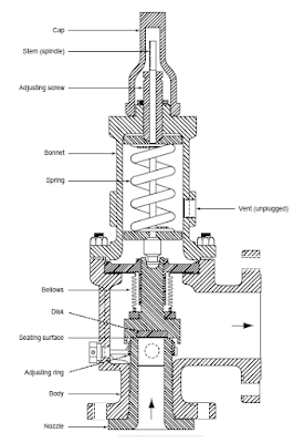
Balanced-bellow PSV (typical)

Balanced-piston PSV (typical)
Subscribes to FREE Hydrocarbon Processing
Pilot operated PSV
Compare to a balanced-bellow PSV, a balanced-piston PSV bonnet is extended with insertion block and balanced piston. This type of PSV is commonly used in system with fluid temperature potentially drop below sub-zero i.e. NGL recovery plant, LNG production plant, etc during relief and in case of leakage or passing.
Pilot operated PSVCompare to a balanced-bellow PSV, a balanced-piston PSV bonnet is extended with insertion block and balanced piston. This type of PSV is commonly used in system with fluid temperature potentially drop below sub-zero i.e. NGL recovery plant, LNG production plant, etc during relief and in case of leakage or passing.
A pilot operated PSV is a pressure relief valve in which the major relieving device or main valve is combined with and controlled by a self actuated auxiliary pressure relief valve (pilot). See below images. T

Pop action & flowing type pilot operated PSV
Compare to conventional type and balanced type PSV, pilot operate PSV design and construction have following advantages :
Following is a video clip presented typical construction and operation of a conventional PSV.
Related Posts
- allow PSV inlet non-recoverable line loss higher than 3% of PSV set pressure (conventional PSV and balanced bellow PSV limit to maximum of 3% of set pressure). Read more "concerns & recommendations on PSV INLET line" and "How to Resolve Issue with PSV Inlet Line Loss Exceeded 3% of Set pressure"
- allow maximum operating pressure upto 95% of PSV set pressure. Some PSV can allow upto 97-98% of PSV set pressure (as compare to 90% set pressure which typically for conventional and balanced bellow PSV)
- can tolerate very high back pressure (>50% of set pressure. Required manufacturer confirmation)
Following is a video clip presented typical construction and operation of a conventional PSV.
Typical construction and operation of a conventional PSV
(Click here to view from Browser - Recommended)
(Click here to view from Browser - Recommended)
Related Posts
Labels: Overpressure Protection, Pressure Relief Device
Wednesday, December 3, 2008
Display problem ? Click HERE
Recommended :
- Subscribe FREE - Processing Magazine
- Tips on Succession in FREE Subscription
Pressure vessel are commonly used in oil and gas, LNG, refining, petrochemical plant. These pressure may be designed to code such ASME, JIS, GB, AS, etc. It is subject to location of the plant, local regulation of applicability of these code. For example, if the plant is located in China, the pressure vessel may be designed to GB150 or ASME with neccessary adoptation (subject to changes from time to time). These codes mandated pressure vessel shall be protected from any overpressure scenarios by cenventional mechanical based pressure relief device i.e Pressure Relief Valve (PRV), Rupture disc (RD), etc. However, in some special applications and overpressure scenario, the use of pressure relief devices is impractical. In this post, will discuss a bit on those cases make pressure relief devices impractical and what may be considered.
Impractical cases
Following are some typical cases make conventional pressure relief devices impractical :
Application of Code Case 2211
Adoptation of ASME code case 2211 (1996, revised in 1999) by use of instrumented system to protect against overpressure. In this Code Case, ASME has adopted the opinion that, “a pressure vessel may be provided with overpressure protection by system design in lieu of a mechanical relief device,” with following conditions :
a) The vessel is not exclusively in air, water or steam service unless these services are critical to preventing the release of fluids that can result in safety or environmental hazards.
b) The decision to provide a vessel with overpressure protection by system design is the responsibility of the user. The manufacturer is responsible only for verifying that the user has specified overpressure protection by system design and for listing this code case on the data report.
c) The user shall ensure that the Maximum Allowable Working Pressure (MAWP) of the vessel is greater than the highest pressure that can reasonably be expected to be achieved by the system. The user shall conduct a detailed analysis of all credible overpressure scenarios. This analysis shall utilize an organized, systematic process safety analysis approach such as a hazards and operability (HAZOP) review, a failure modes, effects and criticality analysis (FMECA), fault tree analysis, event tree analysis, what-if analysis or other similar methodology.
d) The analysis described in (c) shall be conducted by an engineer(s) experienced in the applicable analysis methodology. The results of the analysis (including a qualitative or quantitative evaluation of reliability) shall be documented and signed by the individual in charge of the operation of the vessel. The documentation shall be made available to all authorities having jurisdiction at the site where the vessel will be installed. The user is cautioned that prior jurisdictional acceptance can be required.
e) The code case number shall be shown on the manufacturer’s data report and it shall be noted that prior jurisdictional acceptance may be required.
Above typically leads to the applicable of High Integrity Protection Systems (HIPS). One use this HIPS shall always ensure the Safety Integirty Level (SIL) of the protective system shall always equal or higher than what can be delivered by a pressure relief device. Read more in "Is Single PSV Protection Sufficient ?".
Related Posts
- Subscribe FREE - Processing Magazine
- Tips on Succession in FREE Subscription
Pressure vessel are commonly used in oil and gas, LNG, refining, petrochemical plant. These pressure may be designed to code such ASME, JIS, GB, AS, etc. It is subject to location of the plant, local regulation of applicability of these code. For example, if the plant is located in China, the pressure vessel may be designed to GB150 or ASME with neccessary adoptation (subject to changes from time to time). These codes mandated pressure vessel shall be protected from any overpressure scenarios by cenventional mechanical based pressure relief device i.e Pressure Relief Valve (PRV), Rupture disc (RD), etc. However, in some special applications and overpressure scenario, the use of pressure relief devices is impractical. In this post, will discuss a bit on those cases make pressure relief devices impractical and what may be considered.Impractical cases
Following are some typical cases make conventional pressure relief devices impractical :
- Process reaction involve polymerization, crystallization, solidification, etc during normal operation. Historically the product partially/compeltely plug / block the pressure relief flow path. Some recommendations have been discussed in "Concerns & Recommendations on PSV INLET line".
- Relieved reactants in flare header potential polymerized, crystallized, solidified during relieving and partially / completely plug / block the discharge tail pipe, lateral, etc.
- Gassy or foamy system which possibly leads to exceesively large pressure relief device and flow path. Normally this kindly of gassy and foamy system, the prediction of relieving rate is difficult and complicated. This kindly of system may times required laboratory test and scall-up for relief load prediction.
- Rapid chemical reactions with expansion results quick pressure propagation and loss of containment prior to the relief device opening. Typical examples are water hammer, “hot spots,” decompositions, and internal fires.
- Rapid exothermic chemical reactions accelerate chain reaction and rapid expansion. Intenal pressure could build up exponentially leads to loss of containment prior to the relief device opening.
- Extremely large relief load due to rapid chemical reactions lead to impractical disposal system capacity
- Large relief load and impractical to design a disposal system to handle the relieved fluid
- The relieved fluid possibly created secondary hazardous to surrounding and damage to environment
Application of Code Case 2211Adoptation of ASME code case 2211 (1996, revised in 1999) by use of instrumented system to protect against overpressure. In this Code Case, ASME has adopted the opinion that, “a pressure vessel may be provided with overpressure protection by system design in lieu of a mechanical relief device,” with following conditions :
a) The vessel is not exclusively in air, water or steam service unless these services are critical to preventing the release of fluids that can result in safety or environmental hazards.
b) The decision to provide a vessel with overpressure protection by system design is the responsibility of the user. The manufacturer is responsible only for verifying that the user has specified overpressure protection by system design and for listing this code case on the data report.
c) The user shall ensure that the Maximum Allowable Working Pressure (MAWP) of the vessel is greater than the highest pressure that can reasonably be expected to be achieved by the system. The user shall conduct a detailed analysis of all credible overpressure scenarios. This analysis shall utilize an organized, systematic process safety analysis approach such as a hazards and operability (HAZOP) review, a failure modes, effects and criticality analysis (FMECA), fault tree analysis, event tree analysis, what-if analysis or other similar methodology.
d) The analysis described in (c) shall be conducted by an engineer(s) experienced in the applicable analysis methodology. The results of the analysis (including a qualitative or quantitative evaluation of reliability) shall be documented and signed by the individual in charge of the operation of the vessel. The documentation shall be made available to all authorities having jurisdiction at the site where the vessel will be installed. The user is cautioned that prior jurisdictional acceptance can be required.
e) The code case number shall be shown on the manufacturer’s data report and it shall be noted that prior jurisdictional acceptance may be required.
Above typically leads to the applicable of High Integrity Protection Systems (HIPS). One use this HIPS shall always ensure the Safety Integirty Level (SIL) of the protective system shall always equal or higher than what can be delivered by a pressure relief device. Read more in "Is Single PSV Protection Sufficient ?".
Related Posts
- Is Single PSV Protection Sufficient ?
- Concerns & Recommendations on PSV INLET line
- Few Concerns & Recommendations of PSV Discharge Tail pipe
- Where to Locate the PSV Inlet Nozzle ?
- Parallel Valve Technology Increase Safety & Reduce Nuisance Trips
- Dust Explosion Basic & Protection
- Requirements of SDV Bypass Pressurization Line
Labels: Overpressure Protection, Pressure Relief Device
Monday, December 1, 2008
Display problem ? Click HERE

If you have successfully subscribed to FREE Chemical Engineering magazine, you should be received a note from the publisher requesting you to participate a survey in order to help in making Chemical Engineering an even more interesting and informative publication for readers like you. Chemical & Process Technology webblog members strongly encourage you to participate this survey.
Why ?
Reason being
i) to provide your inputs to make Chemical Engineering more valuable.
ii) to serve your commitment to Chemical Engineering magazine as a free magazine subscriber
iii) to increase your "points" so that you qualify again for free Chemical Engineering during next renewal
iv) Stand a chance to win $100
What to do ?
What you really need to do is just follow up Chemical Engineering October 2008 issue and evaluate a sample of 19 articles and advertisements appearing in the issue.
Chance to win $100
With your participation, you will have a chance to win $100 Visa debit gift card.
FREE Chemical Engineering Subscription Released again ! Just released yesterday. Quick before they are fully subscribed. Click here to qualify your FREE Chemical Engineering !
Related Post
Labels: E-Doc, Education, Learning
