Saturday, May 31, 2008
Display problem ? Click HERE
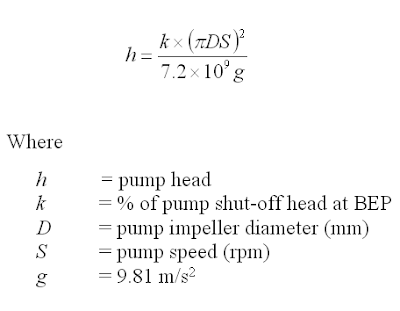
 A process plant is in debottlenecking phase and a pump is expected to be changed out. A datasheet submitted by pump vendor and stated the impeller size is 295mm with pump head of 120m as requested. The pump speed is expected to be high speed pump with 2950 rpm. Do you think this impeller can deliver the head ?
An short-cut equation is derived from velocity and head can be used to check if the pump head is good.
Recommended Utility :
 Base on above equation, impeller size of 295mm, pump speed of 2950 rpm, and k normally is about 85%, the calculated pump head is about 90m (less than 120 m). It imply that the pump head may be over-estimated. Thus, a quick verification with pump vendor shall be done.
Labels: Pump
Friday, May 30, 2008
Display problem ? Click HERE
 Chemical & Process Engineer regardless serving design or operation, activities such as calculation, presentation, data collection, analysis and management, etc, have become a common daily activities. Several tools such as Excel, Powerpoint, Outlook, Lotus notes, etc are commonly use to accelerate these activities and enhance performance.
CustomGuide founded in the 1990s by a group of instructors and has become one of the world's leader for customizable computer training and assessments. CustomGuide offers computer training course, reading material, online learning, skills assessment demons and customized computer training. Those training courses includes all tools as mentioned above.
Apart, CustomGuide offers FREE references for these tools. You may download as you wish :
Microsoft FrontPage
Apart, CustomGuide offers FREE references for these tools. You may download as you wish :
Microsoft Access
Microsoft Excel Microsoft InfoPath
Microsoft Office
Internet Explorer Microsoft Project Microsoft Publisher
Microsoft SharePoint
Microsoft Visio
Microsoft Windows
Microsoft Word
Acrobat for Windows
Dreamweaver for Mac
Fireworks for Windows
Fireworks for Mac
Flash for Windows
Photoshop for Mac
Photoshop Elements for Windows
Computer Training
BELOW are for MAC users
Apple Appleworks
Apple Mac OS
Microsoft Entourage
Microsoft Excel
Microsoft PowerPoint
Microsoft Word
If you have any others (links as well) would like to share with other blog readers, please put in the Comments column
(click here to browse page)
Related Posts
(click here to browse page)
Related Posts
- Instrumentation and Formulae & Conversion...
- R&D engineer, Academician and Student...Don't miss this !
- FREE E-book........A Heat Tranfer Textbook
- WOLVERINE - Offer FREE Heat Transfer Engineering Databook...
- Workbook for Chemical Reactor Relief System Sizing
- A must have book...Emergency Relief System Design Using DIERS Technology
Labels: Ebook
Thursday, May 29, 2008
Display problem ? Click HERE
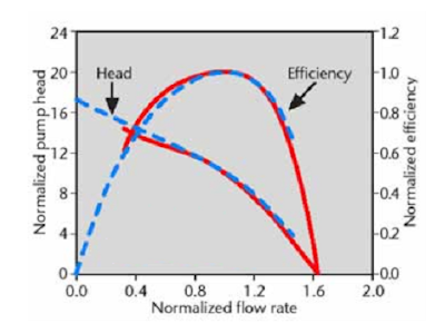
 Recommended :We have been talking about the benefits of Variable Frequency Drive (VFD) for pump in Many Aspects. However, no single rule govern all scenario. Similarly, use of VFD for pump may not apply to all application. Thus, Affinity laws is applied to show the performance varies with speed in order to decide if application of pump with VFD for a particular scenario is feasible and variable.
Read details in "When Should Variable Speed Drives be used to Save Energy?"
Related Post
- Variable Frequency Drive (VFD) helps in Many Aspects
- Estimate Saving with Variable Speed Control (VSC) compare to other Control Method for FANs
- Quatitatively compare Variable Speed Control (VSC) with Conventional Flow Control in Pumping system
- Consider energy saving by optimizing the pump control
- Do not under estimate pump energy cost and FREE Optimization tool for better Life cycle cost
- Restrcition Orifice Used in Many Applications in Different Manners
Labels: Pump
Wednesday, May 28, 2008
Display problem ? Click HERE
A task assigned to a young engineer who has just graduated from University with good grade. He is requested to conduct a detailed pump hydraulic calculation. One of the routine information required to be calculated is to determine the motor rating and estimate the pump power consumption to estimate the overall power demand, hence to determine the power generation capacity. In order to determine pump power consumption, its motor rating shall be determined first. Pump motor rating required pump shaft power estimation as design condition. A general equation widely used to calculate pump shaft power is
A task assigned to a young engineer who has just graduated from University with good grade. He is requested to conduct a detailed pump hydraulic calculation. One of the routine information required to be calculated is to determine the motor rating and estimate the pump power consumption to estimate the overall power demand, hence to determine the power generation capacity. In order to determine pump power consumption, its motor rating shall be determined first. Pump motor rating required pump shaft power estimation as design condition. A general equation widely used to calculate pump shaft power is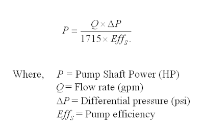
 Normally the pump efficiency is provided by the pump vendor.
What would be the pump efficiency value if pump have not been selected ?
One of the formula common used to estimate pump efficiency is as follow :
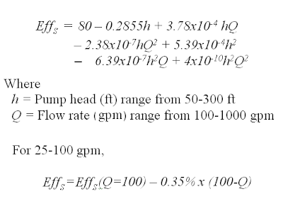
Above equation has limited to 300 feet and 1000 gpm, for larger head and flow, please refer to "Estimate Pump Efficiency base on Specific Speed (Ns)".
Labels: Pump
Tuesday, May 27, 2008
Display problem ? Click HERE
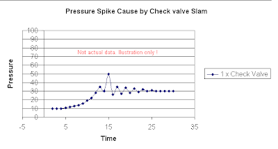
Discussion in "How to predict Check Valve Slam ?" has shown potential of surge pressure if a normal check valve is provided in the pump discharge. Nevertheless, in many design the surge pressure could be within the allowable limit of piping short term pressure spike. Thus, it is "normally" that providing a normal check valve on pump discharge does not poses any danger of pressure surge. Having said this, a proper checking should be carried out.
One of the scenario that has been warned for many times is providing double check valves in the pumping system. With single normal check valve in the pump discharge line, the discharge may experience a short term pressure spike as shown in image below.
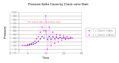
In case of double check valves in the pumping system, there may be a very short time gap between the closure of both check valves. This would allow both check valves generate two pressure waves running forward and backward along the pumping system. Two waves would probably meet along the piping. Both waves' amplitude could be added or subtracted between each and other subject to wave's pattern. A severe pressure spike could be additional of two identical waves as shown in the following image.
Above discussed about the potential of severe pressure spike in the pumping system with double check valves, however, it very subject to :
- Shutdown valve closure time
- Pump shutdown time and its impact on the pressure waves
- Piping length
- Location of the check valves
- Check valves type and its closure time
thus, providing double check valves does not mean severe pressure spike will definite happen. However, the potential of severe pressure spike increases as well as it associate risk. Only proper pressure surge study and review on the wave and pressure spike pattern can advise the likelihood of occurrence.
Related Post
- How to predict Check Valve Slam ?
- How to Select a Check Valve (NRV) Quantitatively ?
- Why Redundant NRV in Series within a Line ?
- Why bypass Non-Return Valve (NRV) ?
- Tips for Centrifugal Pump
Labels: Fluid Flow, Hydraulic, NRV, Surge
Monday, May 26, 2008
Display problem ? Click HERE

Don't weak-up the Sleeping Dragon in the East ! This is one of the talk being heard for many years. What this Sleeping Dragon in the East ? Yes...China ! Recently heard development in China was tremendously fast especially in large city such as Beijing, Shanghai and GuangDong. Although this fast development is a reality, however, there are still many peoples including engineer are still having problem in communication and reading in English. They are still prefer to read Chinese.
Following this fast development in China, most large companies have start to add Chinese wording website in addition to their ordinary website which normally in English. This is one of the effort to capture the Chinese market. Another effort would be publish or translate article in Chinese. This clearly shown by our well known magazine publisher, Chemical Engineering.
Chemical Engineering has recently published the CHEMICAL ENGINEERING Supplementary issue which has been written in Chinese. If you are can read Chinese wording, probably you will have another way to read Chemical Engineering. Click here or following image to read.

In addition to capture readers from China and attracts more advertisers interest in advertising in this magazine, Chemical engineering supplementary (in Chinese) may also attract many professional engineer in China publish their article in Chemical Engineering. This is really a great move by Chemical Engineering.
India is another country in fast development competing with China. When will be the release of Chemical Engineering in India language ? From marketing perspective, guess this probably will realize soon !
Professional engineer from India, what do you think ?
Interesting Articles
Professional engineer from India, what do you think ?
Interesting Articles
Sunday, May 25, 2008
Display problem ? Click HERE
The discussion on pump cavitation have been circulated around what is pump cavitation ? how destructive a cavitation ? how cavitation sound & looks like ? what the relationship between NPSHa & NPSHr ? how to increases NPSHa to minimize / avoid cavitation ?...One of the important topic is real life operation, detection of pump cavitation during operation. A pumping system may be designed and constructed for pump cavitation free as well as normal operation. Whenever some parts within pumping system is deteriorated, fluid degradation, suction condition change, pump suction and impeller wear-&-tear, would lead to short term intermittent or long term cyclic or continuous pump cavitation. This cavitation may not easily be detected.
There are several symptoms of pump cavitation. During pump cavitation :
There are three ways to detect pump cavitation.
i) Visual & Noise detection.
An experienced operator standing beside a cavitating pump can fairly easily distinguish noise caused cavitation than other machinery noise. However, there are large amount of pumps in a plant, it is almost impossible to locate operator near pumps in order to identify intermittent cavitation.

ii) Detection by Vibration level monitoring
Another method to detect occurrence of pump cavitation is continuous monitor vibration level of the pump. The is one the mature method nowadays. The vibration level signal is transmitted continuously to condition monitoring system. It can be programmed to provide signal and alarm to alert operator. Following is vibration trend line shows pump normal operation, partial cavitation, full cavitation before it is shutdown.
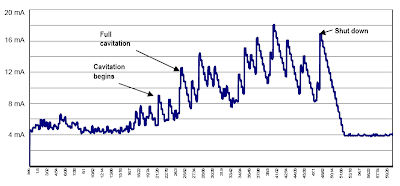
The vibration level trend line can be available for preventive maintenance analysis. This method can provide information on early detection of potential of pump cavitation so that maintenance group can take early actions.
iii) Detection by Acoustic Emission (AE) analysis
As high frequency noise is emitted during cavitation, Acoustic Emission (AE) technique in condition monitoring of rotating machinery can be used to detect pump cavitation. AE technique basically providing a AE detector several feet away from the pump to capture acoustic level.
Related TopicThere are several symptoms of pump cavitation. During pump cavitation :
- Severe noise
- Drops in flow
- Power consumption increases
- vibration
- instable
There are three ways to detect pump cavitation.
i) Visual & Noise detection.
An experienced operator standing beside a cavitating pump can fairly easily distinguish noise caused cavitation than other machinery noise. However, there are large amount of pumps in a plant, it is almost impossible to locate operator near pumps in order to identify intermittent cavitation.
Courtesy of Wilcoxon Research Inc.
ii) Detection by Vibration level monitoring
Another method to detect occurrence of pump cavitation is continuous monitor vibration level of the pump. The is one the mature method nowadays. The vibration level signal is transmitted continuously to condition monitoring system. It can be programmed to provide signal and alarm to alert operator. Following is vibration trend line shows pump normal operation, partial cavitation, full cavitation before it is shutdown.
The vibration level trend line can be available for preventive maintenance analysis. This method can provide information on early detection of potential of pump cavitation so that maintenance group can take early actions.
iii) Detection by Acoustic Emission (AE) analysis
As high frequency noise is emitted during cavitation, Acoustic Emission (AE) technique in condition monitoring of rotating machinery can be used to detect pump cavitation. AE technique basically providing a AE detector several feet away from the pump to capture acoustic level.
- How to Increase NPSHa to a Pump ?
- Relationship between NPSHa & NPSHr
- Damages by Cavitation
- Why Cavitation is Destructive ?
- How Pump Cavitation Sound and Looks Like ?
- Why Centrifugal pump NPSH required increases with flow ?
- Rule-of-thumb For Minimum Flow Recycle
Labels: Pump
Saturday, May 24, 2008
Display problem ? Click HERE
Researcher reported that certain carbon nanotube structure (long, thin carbon nanotubes) might cause cancer for long exposure within sufficient quantities inhaled. Carbon nanotube (long & thin) has some properties close to asbestos which potentially cause mesothelioma, a cancer of the lung lining that take 30 years to manifest.
The good news is short carbon nanotube may not pose similar cancer risk than long, thin carbon nanotubes.
The good news is short carbon nanotube may not pose similar cancer risk than long, thin carbon nanotubes.
Read more in
- Nanotechnology cancer risk found
- Nanotubes could pose cancer risk
- Research: Nanotubes Could Pose Asbestos-Like Cancer Risk
- Carbon nanotubes bad as asbestos
This is one the development where all new stuff will have to be gone through as we understood it more and more. Although it pose some level of risk, however sufficient precaution and procedure in place shall be able to minimize and avoid the consequence. General saying : Risk can not be avoided but can be managed. Those who are advancing their interests and works in nanotube study and production is encourage (shall) to take quick actions.
Labels: NanoTech, Technology
Friday, May 23, 2008
Display problem ? Click HERE
 Google, well known giant internet search engine provider, is now planning into the energy business. Its main headquarters in Mountain View, California is being powered solar energy, as understood it is one of the largest solar electric installations in the United States.
As part of the continuous move into renewable energy, Google has planned to invest $20 million in the next year toward renewable energy research. The move include hiring between 20 and 30 new employees and renewable energy experts.
The main goal for present move is to find a great way to reduce the cost of renewable energy generation to bring it more on par with the cost of coal.
Read more in Google Pours Massive Investment into Renewable Energy Research
Related Post
- Why not bury flare pipe header ?
- What you can do to help our friend "Environment" ?
- Theme for Blog Action Day - ENVIRONMENT
- Get The Most out of Waste Heat (Exergy approach)
- Factors and Criteria for Vent Stack Design
Labels: Energy, Environment
Thursday, May 22, 2008
Display problem ? Click HERE
Kunal, a student from India has asked a rather simple question.
What is the function of VALVE ?
This question has triggered me to take a little effort to tabulate :
i) Isolation
Valve has been commonly used for system isolation and positive protection i.e. shutdown valve. Valve used for isolation purposes generally are ball, gate and butterfly.
ii) Throttling & control
Varying opening of flowing path area in valve would be able to limit quantity of fluid passing the valve and serve the throttling and control purposes. Valve used for throttling and control purposes generally are globe, needle, special designed control valve, etc.
iii) Overpressure & Vacuum protection
Valve also use for system overpressure & vacuum protection. For overpressure protection, fluid is contained in system during normal operation. Whenever the system pressure increase, the valve will open to relief fluid to ensure system pressure below maximum allowable working pressure of the system. Valve use for his purpose is generally spring loaded pressure relief valve and pilot-operated pressure relief valve. Similar principle apply to vacuum protection but the difference is only allowing fluid enter into system to avoid vacuum.
iv) Avoid back flow
Valve with piston, flapper, etc would allow fluid flowing forward. Whenever fluid flow backward, the piston & flapper will close the flow path and restrict fluid back flow. Valve is normally called check valve or non-return valve.
v) Pump minimum flow protection
Valve like ARC valve is a self-contained valve which contain the check valve feature while allowing flow diversion during low flow. This is a good combination in pumping system where it demand back flow protection to avoid impeller damage and minimum flow protection during low flow.
Related Topic
Related Topic
Labels: Control valve, Emergency Shutdown
Wednesday, May 21, 2008
Display problem ? Click HERE
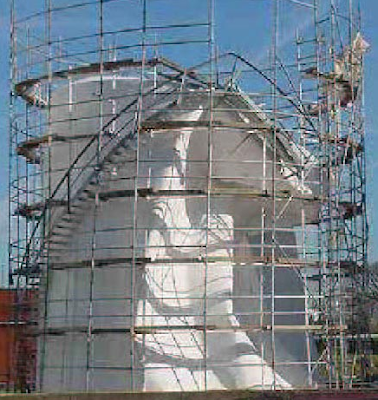
"Vacuum Hazard - Another Catastrophic Factor..." discuss about the damage of vacuum, main factors resulting Vacuum and several scenario may lead to Vacuum Hazard. "4-steps Approach to Combat Vacuum Hazard" discuss about approach may be taken to minimize and avoid Vacuum Hazard.
The following video clip will demonstrates how powerful is ATMOSPHERIC pressure and how quick a "vessel" collapse.
* Click here to view video clip via browser...
Related Post
Have your ever seen how quick a "vessel" collapse ?
The following video clip will demonstrates how powerful is ATMOSPHERIC pressure and how quick a "vessel" collapse.
Courtesy of Lightmypump
* Click here to view video clip via browser...
Related Post
Tuesday, May 20, 2008
Display problem ? Click HERE
A centrifugal pump feeding liquid to a heat exchanger located downstream. Check valve is provided between pump and heat exchanger to avoid back flow damaging the pump impeller. As the heat exchanger design pressure is lower than the pump shut-in pressure, A pressure relieve valve (PRV) is provided just upstream of the heat exchanger to avoid overpressure during pump shut-in condition. A shutdown valve (SDV) is located downstream of the heat exchanger for system isolation purpose. Both heat exchanger and SDV are located at one deck (~ 10m) higher than the pump. In the event of system shutdown, the Emergency Shutdown System (ESD) will initiate shut close of SDV and pump stop. Above arrangement is pretty standard in Chemical plant or Oil & gas plant.
When the system is commissioned and put under operation, everything run smooth. Nevertheless, the PRV open and slam close whenever the system shutdown. What was the problem ?
Why PRV passing during shutdown?
After some level of analysis, the following were postulated :
i) Whenever the system (pump & SDV) shutdown, the closure of SDV and lead to incompressible liquid back flow to check valve (in wave motion). The check valve slam (ordinary check valve) and lead to forword wave . The forward and backward wave would subsequently lead to pressure spike in the line and resulting opening of PRV. Read "How to predict Check Valve Slam ?" to get more insight into how ordinary check valve lead to pressure spike.
ii) As the heat exchanger and SDV is located ~ 10m above the pump & check valve, whenever the pump stop and check valve closure, liquid column would induce back flow and further increase the pressure spike.
iii) Pump rotate in forward direction would have substantial inertial and take longer time from full speed to zero speed. However, SDV would have much shorter closing time from full open to full close position. Apart from pressure spike caused by the ordinary check valve & SDV, the reducing forward flow would further increase the potential of pressure spike.
All aboves lead to pressure spike and potential lifting PRV.
How to avoid ?
Few approaches may be considered to minimize / avoid above situation :
a) Conduct surge analysis and check the potential of pressure spike
b) Use Non-Slam Check valve (if requried). Read "How to predict Check Valve Slam ?"
c) Increase SDV closing time. Read "Maximum Allowable Time from Shutdown Initiation to SDV Fully Closed" for maximum SDV closing time.
d) Use surge suppressor.
Related Post:
- How to predict Check Valve Slam ?
- Maximum Allowable Time from Shutdown Initiation to SDV Fully Closed
- A Technical Report for Partial Stroke Testing of Automated Block Valves
- Partial Stroke Testing for Emergency Shutdown Valves
- Requirements of SDV Bypass Pressurization Line
- 12 Features required for Shutdown Valve (SDV)
Labels: Emergency Shutdown, Pressure Relief Device, Pump
Monday, May 19, 2008
Display problem ? Click HERE
Pressure Relief Device (PRV) inlet line lose shall be limited to 3% of set pressure while the outlet built-up back pressure shall be limited to 10% for a conventional PRV and 30 for balanced PSV (without affecting it flow).
Excessive PRV inlet loss can result rapid opening and closing of the valve which normally called chattering. Chattering will result in lowered capacity and damage to the seating surfaces. The inlet line loss here is referring to non-recoverable entrance losses (turbulent dissipation) and frictional line lose.
The impact of excessive built-up back pressure on discharge piping discussed in "Several Impact of Backpressure on Conventional PRV".
One of the question raised is that should the rated flow or required relieving flow to be considered for inlet line loss and discharge built-up backpressure estimation ? Should the flowing fluid phase affecting this requirement ?
Flowing phase & PRV type
The flowing fluid phase would affect the PRV type. Example, pop action spring loaded PRV is good for compressible vapor or gas service and modulating type PRV is good for incompressible liquid service.
Flowrate to be considered for Discharge line
As per API Std 521, section 7.2.1, table 12, the flowrate to be considered for tail pipe, lateral & main header subject to PSV type (refer table below).
Above is inline with API RP 520 PII - Ed 5 Aug 2003, section 5.3.
Flowrate to be considered for Inlet line
Following API Std 521, section 7.2.1, table 12, the inlet line loss for Modulating type PSV may consider required relieving flow. However, API RP 520 PII - Ed 5 Aug 2003, section 4.2.2. stated :
2-cents opinion
Modulating type PSV is intended to work to modulate the flow passing the PSV. Those theoretically, on the required relieving flow should be passing the PSV. In taking conservative approach and in compliance with API recommendation, rated flow is recommended for modulating type PSV inlet line loss estimation.
Related Post
Excessive PRV inlet loss can result rapid opening and closing of the valve which normally called chattering. Chattering will result in lowered capacity and damage to the seating surfaces. The inlet line loss here is referring to non-recoverable entrance losses (turbulent dissipation) and frictional line lose.
The impact of excessive built-up back pressure on discharge piping discussed in "Several Impact of Backpressure on Conventional PRV".
One of the question raised is that should the rated flow or required relieving flow to be considered for inlet line loss and discharge built-up backpressure estimation ? Should the flowing fluid phase affecting this requirement ?
Flowing phase & PRV type
The flowing fluid phase would affect the PRV type. Example, pop action spring loaded PRV is good for compressible vapor or gas service and modulating type PRV is good for incompressible liquid service.
Flowrate to be considered for Discharge line
As per API Std 521, section 7.2.1, table 12, the flowrate to be considered for tail pipe, lateral & main header subject to PSV type (refer table below).
Above is inline with API RP 520 PII - Ed 5 Aug 2003, section 5.3.
"...The rated capacity of a conventional spring loaded, balanced spring loaded or pop action pilot-operated pressure relief valve should typically be used to size the atmospheric vent piping or the discharge line from the pressure-relief valve to the relief header. Common relief header piping in closed discharge systems should be sized using the protected system's required relieving capacity.
For a modulating pilot-operated pressure-relief valve, the discharge piping can be sized using the required relieving capacity of the system that the valve is protecting..."
Flowrate to be considered for Inlet line
Following API Std 521, section 7.2.1, table 12, the inlet line loss for Modulating type PSV may consider required relieving flow. However, API RP 520 PII - Ed 5 Aug 2003, section 4.2.2. stated :
"When a pressure-relief valve is installed on a line directly connected to a vessel, the total non-recoverable pressure loss between the protected equipment and the pressure-relief valve should not exceed 3 percent of the set pressure of the valve except as permitted in 4.2.3 for pilot-operated pressure relief valves. When a pressure-relief valve is installed on a process line, the 3 percent limit should be applied to the sum of the loss in the normally non-fowing pressure-relief valve inlet pipe and the incremental pressure loss in the process line caused by the flow through the pressure-relief valve. The pressure loss should be calculated using the rated capacity of the pressure-relief valve."API RP 520 PII - Ed 5 Aug 2003 has not clarified if required relieving flow can be used for modulating type PSV.
2-cents opinion
Modulating type PSV is intended to work to modulate the flow passing the PSV. Those theoretically, on the required relieving flow should be passing the PSV. In taking conservative approach and in compliance with API recommendation, rated flow is recommended for modulating type PSV inlet line loss estimation.
Related Post
- Several Impact of Backpressure on Conventional PRV
- Useful Documents Related to Pressure Relief Valve (PRV) - Part 3
- Useful Documents Related to Pressure Relief Valve (PRV) - Part 2
- Useful Documents Related to Pressure Relief Valve (PRV) - Part 1
- Discussion on ISENTROPIC and ISENTHALPIC process via Relief Valve
- Use of conventional type PSV with back pressure exceeded 10% set pressure
Labels: Overpressure Protection, Pressure Drop, Pressure Relief Device
Sunday, May 18, 2008
Display problem ? Click HERE
 Filter is commonly use in Process & Chemical or Oil & Gas plant to separate material in particular phase from another phase. The separation can be
- solid from liquid or vapor e.g. particle filter
- liquid from solid or vapor e.g. cake filtration, coalescer, etc
"Filtration technology is one of the core technologies applied widely to water treatment. It is excellent from economics point of view as equipment and operation costs are relatively low. The operation and maintenance of filtration systems is less complex compared to the maintenance of membrane separation, adsorption, ion exchange and AOP systems. This presentation will highlight a fibre-filter system that has been developed in Korea. Two types of fiber filters, namely, pressure type and gravity type fibre-filters. These filters were tested in pilot plants treating both water and wastewater. Performances of these newly developed fiber filters will be presented and compared against other filter systems."
A talk on Fiber filters will be conducted by Dr. Yun Chang-Han from Sung Shin Engineering Co., Ltd, KOREA, on 10th June 2008 (from 5.30pm - 7.00pm) at IEM new building (formerly known as ICHS building). For PE in MALAYSIA, you will gain 2 CPD hours.
Details refer to following brochure.
Saturday, May 17, 2008

16 organizations have formed European Observatory on Nanotechnologies with the objectives to provide reliable and complete scientific & economic information of nanotechnology to support european decision maker (e.g. government, industry, etc).
16 organizations are :
- Institute of Nanotechnology [IoN] - UK, http://www.nano.org.uk
- VDI Technologiezentrum GmbH [VDI-TZ] - Germany, http://www.vditz.de
- Commissariat à l'énergie atomique [CEA] – France, http://www.cea.fr
- Institute of Occupational Medicine [IOM], http://www.iom-world.org
- Malsch TechnoValuation [MTV] – Netherlands, http://www.malsch.demon.nl
- triple innova [triple innova] - Germany, http://ti.triple-innova.de
/index_en.php - Spinverse [Spinverse] – Finland, http://www.spinverse.com
- Bax & Willems Consulting Venturing [B&W] – Spain, http://www.bwcv.es
- National Institute for Public Health and the Environment [RIVM] – Netherlands, http://www.rivm.nl
- Technical University of Darmstadt [TUD] – Germany, http://www.philosophie.tu
-darmstadt.de - AIRI/Nanotec IT [AIRI] – Italy, http://www.nanotec.it
- Nano and Micro Technology Consulting [NMTC] – Germanyhttp://www.nmtc.de
- Eidgenössische Materialprüfungs und Forschungsanstalt [EMPA] – Switzerland, http://www.empa.ch
- Nanoethics Centre, University of Aarhus [AU] – Denmark, http://www.teo.au.dk
- UNU-MERIT [MERIT] - Netherlands, http://www.merit.unu.edu/
- Technology Centre AS CR [TCASCR] – Czech Republic, http://www.tc.cz
They are main from UK, Germany, France, Netherland, Finland, Spain, Italy, Switzerland, Denmark and Czech Republic.
Labels: NanoTech, Technology
Friday, May 16, 2008
Display problem ? Click HERE
An Uninterruptible Power Supply (UPS) or Continuous Power Supply (CPS) is a power supply system continuously maintains power supply to connected equipment from a separate source when main power supply is not available. There are off-line, line-interactive and double conversion type of UPS system.
In Process & Chemical or Oil & Gas plant, critical equipment such as control panel, computer, etc will be kept online to facilitate safe shutdown and quick restart-up. A half-day seminar on UPS will be conducted by Bernard Lee, a product manager with Eaton Power Quality on 23rd May 2009 at Wawasan Professional Training Center, dataran menteri Bandar Sunway. Details refer to following brochure.
Thursday, May 15, 2008
Display problem ? Click HERE
Quick update to IEM members...
The details content of this report are tabulated below.
- Cover Page
- Contents
- Past Presidents,IEM Distinguished Honorary Fellow,IEM Honorary Fellows,IEM Functions,Council Members for Session 2007/2008, Notice of 49th Annual General Meeting,Proposed Amendments to IEM Constitution
- Executive Committee of Council,Board of Management IEM Education Fund,Board of Management IEM Benevolent Fund,External Auditors and Honorary Internal Auditors,Standing Committees,Sub-Committees/Ad Hoc Committees/Special Committees,Technical Divisions/Interest Groups/Graduate and Student Section
- Regional Branches,Organising Committees/Position Papers Committees/Technical Committees,IEM Representatives to Outside Bodies
- IEM Outstanding Engineering Achievement Award,IEM Award for Contribution to Engineering Profession in Malaysia,World Federation of Engineering Organisation (WFEO) Award,The ASEAN Outstanding Engineering Achievement Award,IEM Young Engineer Award,IEM Lady Engineer Award
- Minutes of 48th AGM
- List of Attendance for the 48th AGM
- Minutes of 48th AGM (Bahasa Malaysia Translation),Structure of Council - Session 2007/2008
- Organisation Chart-Session 2007/2008
- Council Members for Session 2007/2008
- Executive Committee for Session 2007/2008, IEM Secretariat
- Snapshots of Activities Held in Session 2007/2008
- Snapshots of Activities Held in Session 2007/2008(2)
- 49th Annual Report Session 2007/2008
- Summary Sheet of Activities for the 2007/2008 Session
- Financial Statements for the Year Ended 31 December 2007
- Pie Chart
- Educational Fun
Wednesday, May 14, 2008
Display problem ? Click HERE
Vapor Liquid separation can be simulated in HYSYS using 2-phase separator. Following is an example with below feed gas at 32 barg @ -30 degC feeding a vapor liquid separator. Feed gas composition are N2 (0.38%), CO2 (0.68%), C1 (90.4%), C2 (4.1%), C3 (2.6%) and nC4 (1.84%), all in mole percent. Demister is provided in the vapor phase and maximum allowable pressure of 15 kPa is assumed. Those would like to understanding details of demister, read more in "Quick Understanding & Estimation of Mist Eliminator in Gas-Liquid Separator".
Why liquid in Vapor outlet ?
Above has been simulated HYSYS. It is pretty simple using 2-phase separator module in HYSYS. One of observation is the vapor outlet stream contains liquid. Vapor outlet from 2 phases separator should be in vapor phase. Why HYSYS predict present of liquid in vapor outlet ?
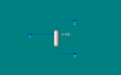
When pressure drop is allocated on the demister by entering pressure drop at "Vapour outlet", HYSYS view it as pressure drop on the vapor stream, outlet of 2-pases separator module. Vapor from separator is saturated vapor and pressure drop on the saturated vapor would result condensation due to Joule-Thompson (JT) effect. A liquid generated will be carried into the Vapor stream.
How to properly simulate a separator ?
In real separation, liquid generated in the demister (due to JT effect) will coalesce, formed larger droplet, trap by demister, droplet is separated from vapor leaving the separator and drop into liquid phase by gravity force. Thus, above straight forward simulation does not really represent a true separation. A proper simulation may include a "dummy separator" with zero pressure drop, downstream of the vapor outlet (2 phases). Separated liquid is mixed with feed stream using a "dummy pump". With this method, the vapor outlet from "dummy separator" will represent the true vapor from the separator. In this method, the "dummy separator" represent the demister and "dummy pump" represent the gravity form.
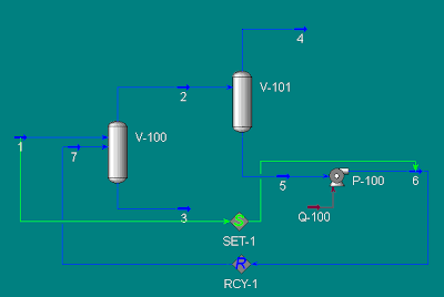
Above is just a simple trick for simulation and many may ignore it or do not even aware of this phenomenon. However, it is pretty important in presenting a true & correct Heat & Material Balance.
Related Topic
- Quick Understanding & Estimation of Mist Eliminator in Gas-Liquid Separator
- AMISTCO (P2) - Extensive info on Mist eliminator, knitted mesh, random & structured packing, distillation
- AMISTCO (P1) - Extensive info on Mist eliminator, knitted mesh, random & structured packing, distillation
- KnitMesh...Good Articles on Mist eliminator still available FREE...
- ACS - Design manual for Mist Eliminators, Trays, Packing, Internals...All in distillation columns
Labels: HYSYS, Separation
