Tuesday, April 29, 2008
Display problem ? Click HERE
Cavitation video clips can be viewed in "How Pump Cavitation Sound and Looks Like ?". There is question raised. Why cavitation is destructive and how it happen ?
Cavitation
Vapor bubbles form when the energy of a liquid molecule is larger than the pressure of the surrounding liquid acting on its surface. As the surrounding pressure decreases, the vapor bubble volume will increase to achieve a balance between vapor bubble energy (vapor pressure) and pressure energy exerted on the vapor bubble surface from surrounding liquid. On the other hand, as the pressure energy is increased and overcome the vapor bubble energy (vapor pressure), the vapor bubble size will reduce until it is totally collapse. Above situation is generally known as Cavitation.
Why cavitation is destructive ?
It is known that cavitation is destructive due to the vapor bubble collapse. Why vapor bubble collpse is destructive ?
Vapor bubble collapsed involve changes state from vapor to liquid. This state change process will generate shock waves. Shock waves are formed by collisions of surrounding liquid molecules that are rushing in to fill the void caused by the collapsing bubble. The shock waves intensity is subject to the speed of bubble collapse and size of bubble. Higher the bubble collapse speed and larger bubble size contains larger kinetic energy (1/2 mv2) and higher shock wave. If this shock wave is toward a surface, it will exert on the surface and severe erosion will occur on the surface. The energy from shock wave will transfer to the surface and potentially create severe vibration.
A study conducted by Y Tomita and A Shima (1990) on formation and collapse of bubble. Following image is a series of photographs shows the progressive collapse of a vapor bubble.
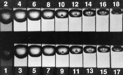
Stage 1 to 6 shows a bubble decreasing in size and flatten.
Stage 7 to 13, a small indentation, known as a “re-entrant micro jet” began to form on the bottom of the bubble, progressively increase and toward upper surface of bubble.
At stage 14, the jet (or shock wave) breaks through the upper surface of the bubble and directs the force of collapse in a single direction. One special phenomenon is the jet direction is always toward a physical surface. Thus, the energy is concentrated and directed towards the surface.
If this happen at surface...
If the cavitation is occured at any surface like pump impeller, control valve trim, etc, erosion at the surface and vibration at the structure would quick leads to damage of the surface and instability of the structure.
Related Topic
Labels: Pump
Monday, April 28, 2008
Display problem ? Click HERE
 Plant debottlenecking project involve increases in capacity (Q) but keeping pressure (P) profile to maintain process performance required installation of new pump either in series or in parallel in order keep existing pressure profile. Optimization of new pump in series or parallel operation will be conducted. The optimization will involve addition of two pumps curve either in series or parallel.
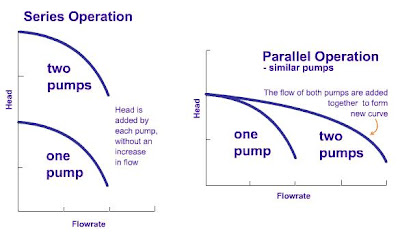
The following Series / Parallel Pump Calculator (EXCEL) has been generated to allows to mix two pump curves and produce a combined performance curve of identical and similar pumps (or pumps with different performance) operate in series and parallel. It also allows you to enter system curve so that you can evaluate their performance. In this Calculator, the unit for head can be feet, meter, mmHg and flow can be gpm, m3/h, etc
Sunday, April 27, 2008
Display problem ? Click HERE
The important, function and implementation of Car Seal Open and Car Seal Close block valves has been briefly discussed in "How CSO and CSC helps ?". Nevertheless, as the car seal strip
- can be easily cut by any cutting tools except the heavy duty type which need special cutting tools
- may deteriorates after exposure to sunlight and severe whether condition
- needs to be replaced once it is cut and incurs additional cost
it still invites question on the reliability & integrity of the security & safety and cost effectiveness of car seal strip. A key locked system increases the security & safety and cost effectiveness on long term basis as compare to car seal option.
The key will be kept in a cabinet in the control room. A strict procedure will be implemented to ensure proper control and handling of the keys.
Second is using the trapped key-lock. See following image.
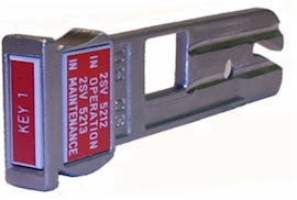
The master key will be kept in the cabinet in control room. It is difficult in duplicating this type of key, it increases the security & reliability of the key locking.
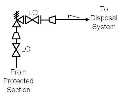
One of the example is locked open (LO) pressure relief valve inlet and outlet isolation valves to avoid operator inadvertently close.
One of the example is locked open (LO) pressure relief valve inlet and outlet isolation valves to avoid operator inadvertently close.
Related Post
- How CSO and CSC helps ?
- Parallel Valve Technology Increase Safety & Reduce Nuisance Trips
- Extra Caution When Eliminating Overpressure by Fire Attacks
- PSV for Shell-and-Tube HEX Tube Side Overpressure Protection against External Fire Attack ?
- Practical Measures to Eliminate or Avoid HX Tube Rupture Scenarios
- Tube Rupture : Pressure Relief Valve (PSV) or Rupture Disk (RD) ?
Labels: Pressure Relief Device, Safety
Saturday, April 26, 2008
Display problem ? Click here
Plant debottlenecking may involve increases in capacity (Q) but keeping pressure (P) profile to maintain process performance. Increased capacity would leads to increases in pumping capacity. To maintain similar pressure profile with increased capacity, a new pump is required. The new pump can be in series or in parallel operation. An optimization study on series or parallel operation would be required in order to provides a configuration with lowest capex, opex and life cycle cost for the pumping system. Prior to the study, probably you needs to understand Meaning of "Pump Head" and differences between pump Pressure and Head.Series & Parallel Operation Identical Pumps
(Part 1 - Click here or here)
(Part 2 - Click here or here)
(Part 1 - Click here or here)
(Part 2 - Click here or here)
Aboves articles would probably provide you with some knowledge of the effect of the system curve on the output of two identical centrifugal pumps operating in parallel and how two pumps curves are added (part 1) and several other factors that can also impact pumping performance (part 2).
Series & Parallel Pump Calculator allow you to mix two pump curves and produce a combined performance curve of identical and similar pumps (or pumps with different performance) operate in series and parallel. Read more...
Related Topic
Labels: Pump
Friday, April 25, 2008
Display problem ? Click HERE
Many of fresh engineer from school or those have not got chance to commission, start-up and operate a plant, you may aware of pump cavitation but have no idea how pump cavitation looks and sound like.
What's Cavitation ?
Cavitation is the formation and collapse of vapor bubbles in a liquid. Bubble formation occurs at a point where the fluid operating pressure is lower than fluid vapor pressure, and bubble collapse or implosion occurs at a point where the pressure is increased to the vapor pressure.
Cavitation is the formation and collapse of vapor bubbles in a liquid. Bubble formation occurs at a point where the fluid operating pressure is lower than fluid vapor pressure, and bubble collapse or implosion occurs at a point where the pressure is increased to the vapor pressure.
Pump Cavitation Sound like...
The following is a video clip showing a centrifugal pump running with pump caviation. You may hear how the sound like when a pump is experiencing cavitation. Whenever you heard similar kind of sound "Ke-tuk-Ke-tuk..." in your pump, you may take action on it...
Pump Cavitation Lookslike...
The following two videos basically let you view cavitation occur at impeller.
Related Topic
The following is a video clip showing a centrifugal pump running with pump caviation. You may hear how the sound like when a pump is experiencing cavitation. Whenever you heard similar kind of sound "Ke-tuk-Ke-tuk..." in your pump, you may take action on it...
The following two videos basically let you view cavitation occur at impeller.
- 3 Preventative Steps to Avoid Early Pump Replacement
- How PlayPump® water System Works ?
- Understand Meaning of "Pump Head"
- Pump Pressure Versus Head
- Why Centrifugal pump NPSH required increases with flow ?
- Tips for Centrifugal Pump
- Rule-of-thumb For Minimum Flow Recycle
Labels: Pump
Thursday, April 24, 2008
Display problem ? Click HERE
Engineers and technicians looking to optimize their process for productive operation can start with protecting the pump against common hazards. Pump protection improves end-product or batch quality, reduces material costs, eliminates waste and lowers maintenance costs. Taking good care of your pump delivers a positive payback. Some simple strategies that can be employed-starting with an analysis of process media flow rates.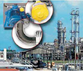
Three preventative, proactive steps to take to avoid early pump replacement :
- When designing new plants or retrofitting old ones, be sure to consider pump requirements. Optimizing your process with your pumps in mind offers a wide range of benefits: higher capacity, improved quality, lower energy costs, reduced maintenance and increased equipment (pump) life.
- Consider inserting a flow conditioner to eliminate turbulent flow problems. Irregular flows caused by turbulence frequently result when the minimum pipe straight runs required between the point of pump suction and elbows, valves or other equipment are either ignored or pushed to the limits. Inserting a flow conditioner frequently eliminates turbulent flow problems.
- Another key safeguard is to protect your pump from accidental low flow or dry running conditions, which can lead to bearing or seal loss requiring expensive repairs. Inserting a dual alarm flow switch in your process loop not only protects the pump from damage, but will alert you to a potential problem and let you be proactive in evaluating the necessity of pump shutdown.
Download from here
Related Topic
Labels: Pump
Wednesday, April 23, 2008
Display problem ? Click HERE
Pool fire is one of the sources of overpressure for a plant facilities which shall be addressed in any design. However, there is a favorite question raised for the extend of the pool fire shall be considered during design phase.
Height
According to API Std 521, Jan 2007, Fifth edition, section 5.15.1.1 "Effect of fire on the wetted surface of a vessel",
To determine vapour generation, it is necessary to recognize only that portion of the vessel that is wetted by its internal liquid and is equal to or less than 7,6 m (25 ft) above the source of flame.
NOTE : Hydrocarbon fires can exceed 40 m (approx. 130 ft) in height; however, experience has shown that it is necessary only to size relief devices on the basis of the averaged heat input up to a height of 7,6 m (25 ft) above the base of a pool fire.
Fire Zone Area
According to API Std 521, Jan 2007, Fifth edition, section 5.20.2.2 "Vapour from fire-heat input", item a)
The extent of an assumed fire zone is a function of the design and installation features that permit confining a fire within a given area (see 4.3.14). Although the size of the assumed fire zone can vary, experience generally indicates that a fire that can be confined to approximately 232 m2 (2 500 ft2) of plotIn general, a circle with diameter of 15.23 m ( 50 ft) can be considered.
Note : Having said that in many occasion, physical separation and fire wall could limit the fire zone area.
Summary
Above API clauses 5.15.1.1 and 5.20.2.2 can be cited in the design in order to define the extend of pool fire in a onshore plant. While determining pressure relieving load under fire contingency and/or fire depressuring, any Pressure relief device (PRD) and/or Blowdown valve / restriction orifice (BDV/RO) within a cylinder with Internal diameter of 15.23 m ( 50 ft) and 7.6 m (25ft) shall be the accumulated.
Related Topic
- How Fluid Characteristic affect 2 phase Relief via PSV on Liquid filled Vessel Exposing to External Fire
- Extra Caution When Eliminating Overpressure by Fire Attacks
- Should we consider JET FIRE for Pressure Relief Valve (PSV) load determination ?
- Requirement of overpressure protection devices on system design to PIPING code
- PSV for Shell-and-Tube HEX Tube Side Overpressure Protection against External Fire Attack ?
- Steam in FIRE...
- Should maximum recommended wall temperature (Tw) for carbon steel vessel used as design temperature ?
- Should we consider JET FIRE for Pressure Relief Valve (PSV) load determination ?
Labels: Fire, Overpressure Protection, Pool Fire, Safety
Tuesday, April 22, 2008
Display problem ? Click HERE
Break-through in Nano Technology by Professor Zhong Lin, Wang Nano Technology research group has caught global interests on his new findings. This new finding have been published and reported worldwide. Part of those are :
Fox News
CCTV
One of the identified issue which is still yet to be resolved is how the generated power being transferred to user and its storage.
Hoping that great works by Professor Wang will provide his research group win the grants offer by E.On in Euro 6 Million Supporting Nanotechnology.
Labels: NanoTech, Technology
Monday, April 21, 2008
Display problem ? Click HERE
Shutdown Valves (SDV) are commonly use in oil and gas production system for safe and proper isolation purpose to minimize escalation of hazardous from one system to another system.
In "12 Features required for Shutdown Valve (SDV)", one of the requirements of SDV is Fast Action.
What is the maximum allowable time from shutdown initiation to SDV fully closed ? Any code or standard can be referred ?
According to API RP 14C, 7th Edition, March 2001, "Recommended Practice for Analysis, Design, Installation, and Testing of Basic Surface Safety Systems for Offshore Production Platforms" Appendix C - Support Systems C.2.1.4. "The time it takes for any safety device (e.g. PSH, BSL, ESD station, etc.) to effect component or platform shutdown should not exceed 45 seconds."
Thus, the upper limit is 45 second. However, quick closing SDV would also lead to transient surge. It is recommended the closing time should be minimum 3-5 second. This is just a recommendation. For a piping which is long, low ductility, carrying incompressible fluid, etc, it increases the potential of pipe failure due to surge. A proper surge analysis may be conducted if it is deem necessary.
Related Post:
In "12 Features required for Shutdown Valve (SDV)", one of the requirements of SDV is Fast Action.
A shutdown valve shall act fast to minimize the escalation of hazards. Generally a quarter ball valve is the excellent device in quick action. As rule of thumb, shutdown valve shall be capable of begin it closing action within 10 seconds of activation, and time taken from Full open to Full Close is within 1-2 seconds per inch of shutdown valve size. However, this shall be compliant to overall safety philosophy.
What is the maximum allowable time from shutdown initiation to SDV fully closed ? Any code or standard can be referred ?
According to API RP 14C, 7th Edition, March 2001, "Recommended Practice for Analysis, Design, Installation, and Testing of Basic Surface Safety Systems for Offshore Production Platforms" Appendix C - Support Systems C.2.1.4. "The time it takes for any safety device (e.g. PSH, BSL, ESD station, etc.) to effect component or platform shutdown should not exceed 45 seconds."
Thus, the upper limit is 45 second. However, quick closing SDV would also lead to transient surge. It is recommended the closing time should be minimum 3-5 second. This is just a recommendation. For a piping which is long, low ductility, carrying incompressible fluid, etc, it increases the potential of pipe failure due to surge. A proper surge analysis may be conducted if it is deem necessary.
Related Post:
- A Technical Report for Partial Stroke Testing of Automated Block Valves
- Partial Stroke Testing for Emergency Shutdown Valves
- Requirements of SDV Bypass Pressurization Line
- 12 Features required for Shutdown Valve (SDV)
Labels: Emergency Shutdown, Overpressure Protection
Sunday, April 20, 2008
Display problem ? Click HERE
"How Fluid Characteristic affect 2 phase Relief via PSV on Liquid filled Vessel Exposing to External Fire" has discussed important of understanding of fluid characteristic in determining the potential of two phase Relief in liquid filled vessel.
For a Non-foamy liquid filled vessel with external heat input, theory and experiments have suggested that the PRV relief can be based on ALL VAPOR venting without considering two phases relief. This inline with API Std 521, Jan 2007, Fifth edition, section 5.15.3.3. (click here to read this particular section).
This post would like to bring to you a great short article written by Dr. Fauske from FAI.
This short article discussed the background theory very briefly on the freeboard void fraction, entrainment velocity, overpressure before onset of all vapor venting, determination required flow area for all vapor venting, etc. Two calculation examples have also included in this short article for better understanding. You may find the method pretty useful to determine the vapor mass flux and flow area which eventually can be used to determine the PRV size.
Related Topic
- How Fluid Characteristic affect 2 phase Relief via PSV on Liquid filled Vessel Exposing to External Fire
- Extra Caution When Eliminating Overpressure by Fire Attacks
- Should we consider JET FIRE for Pressure Relief Valve (PSV) load determination ?
- Workbook for Chemical Reactor Relief System Sizing
- A must have book...Emergency Relief System Design Using DIERS Technology
Labels: Overpressure Protection, Pressure Relief Device, Safety
Saturday, April 19, 2008
Display problem ? Click HERE
Pressure Relief Valve (PRV) mounted on top of a liquid filled vessel exposing to external fire attack, there was a great discussion on the potential of two phase relief via the PSV.
According to API Std 521, Jan 2007, Fifth edition, section 5.15.3.3.,
Above statement is clearly supported by experiments quoted in Emergency Relief System Design Using DIERS Technology, chapter 1, section 7.2.
Above experiments have shown that
Assessing potential of two phase relief via PSV mounted on top of liquid filled vessel exposing to external fire attack, the characteristic of process fluid in the vessel shall be studied carefully.
Related Topic
According to API Std 521, Jan 2007, Fifth edition, section 5.15.3.3.,
Statement from API implies that sustainable two phase relief via PSV for a liquid filled vessel exposing to external fire attack is very unlikely and can be neglected, with the condition the fluid is non-foamy, non-reactive and not captured in narrow-flow passage like jacket vessel. Narrow-flow passage could be extended to PSV inlet pipe which is rather small and discourage vapor-liquid disengagement in the pipe.
The hydraulic-expansion equations given in 5.14.3 may be used to calculate the initial liquid relieving rate in a liquid-filled system when the liquid is still below its boiling point. However, this rate is valid for a very limited time, after which vapour generation becomes the determining contributor in the sizing of the pressure-relief device.
There is an interim time period between the liquid-expansion and the boiling-vapour relief during which it is necessary to relieve the mixtures of both phases simultaneously, either as flashing, bubble, slug, froth or mist flow until sufficient vapour space is available inside the vessel for phase separation. With the exception of foamy fluids, reactive systems and narrow-flow passages (such as vessel jackets), this mixed-phase condition is usually neglected during sizing and selecting of the pressure-relief device. The aforementioned exceptions are discussed further in 5.15.3.4. Experience as well as recent work in this area [53], [54], [55], [56] has shown that the time required to heat a typical system from the relief-device set pressure to the relieving conditions allows for the relief of any two-phase flow prior to reaching the relieving conditions. As such, full disengagement of the vapour is realized at the relieving conditions and the assumption of vapour-only venting is appropriate for relief device sizing.
Experience has shown there is minimal impact on the discharge system for the two-phase transition period. However, the user may consider the impact of transient two-phase flow on the design of the downstream systems.
If a pressure-relief device is located below the liquid level of a vessel exposed to fire conditions, the pressure relief device should be able to pass a volume of fluid equivalent to the volume of vapour generated by the fire.
Determination of the appropriate state of the fluid can be complicated. A typical conservative assumption is to use bubble point liquid.
[53] H. G. FISHER and H. S. FORREST, "Protection of Storage Tanks from Two-Phase Flow Due to Fire Exposure", Process Safety Progress, Volume 14, No. 3, July 1995, pp. 183-199
[54] H. S. FORREST, "Emergency Relief System Design for Fire Exposure with Consideration of Multiphase Flow", 1995 International Symposium on Runaway Reactions and Pressure Relief Design, ISBN 0-8169-0676-9, Published by American Institute of Chemical Engineers, pp. 604-630
[55] H. MOTT and B. SPARROW, "A Simple Relief Valve Rating/Sizing Method for Fire Relief from Liquid-filled Vessels", presentation to API RP-521 Subcommittee, September 30, 2002
[56] L. L. SIMPSON, "Fire Exposure of Liquid-Filled Vessels", paper D29-190-1 presented at the 29th DIERS Users Group Meeting, Las Vegas, NV, April 29-May 1, 2002
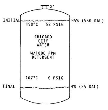
Above statement is clearly supported by experiments quoted in Emergency Relief System Design Using DIERS Technology, chapter 1, section 7.2.
A 2-inch diameter relief device (nozzle) was rapidly opened on a tank that was 95% filled with 550 gallons of city water at approximately 15O0C and under its own vapor pressure of about 58.5 psig. Approximately 28% of the tank contents vented by two-phase flow (See below image).
The experiment was repeated, except that 1000 ppm of a liquid household detergent were added. Approximately 96% of the tank contents vented by two-phase flow (See below image).

Above experiments have shown that
- For non-foamy liquid, two phase relief via PSV will occur in liquid filled vessel until liquid level drop below a a level where vapor liquid disengagement occur. Liquid swelling in the vessel is main factor contributor to two phase relief.
- For foamy liquid, two phase relief would occur in liquid filled vessel until almost all the liquid in the vessel is empty.
Assessing potential of two phase relief via PSV mounted on top of liquid filled vessel exposing to external fire attack, the characteristic of process fluid in the vessel shall be studied carefully.
Related Topic
- Extra Caution When Eliminating Overpressure by Fire Attacks
- Should we consider JET FIRE for Pressure Relief Valve (PSV) load determination ?
- Should we install Butterfly valve for Pressure Relief Valve (PSV) isolation ?
- Requirement of overpressure protection devices on system design to PIPING code
- Workbook for Chemical Reactor Relief System Sizing
- A must have book...Emergency Relief System Design Using DIERS Technology
Labels: Fire, Overpressure Protection, Pressure Relief Device
Friday, April 18, 2008
Display problem ? Click HERE
Those of you conducting research and development in nanotechnology, this could be a great news to you...
E.ON, one of the world’s largest investor-owned power and gas company with 88,000 employees generated EUR69 billion in sales in 2007. Other than power and gas activities in Europe and Russia, E.ON also operate electric and gas utility business and renewable-source generating assets in North America.

E.ON has allocated 6 million euros in research and development funding to NanoTech research and development groups around the world. If your research and development group is focusing on the application of nanotechnology to energy areas like carbon capture and storage, energy storage, and power transmission, your group may consider...
Projects to be considered (but not limited to) :
- Efficiency improvements for renewable energy technologies
- Further developments in Carbon Capture and Storage
- Power lines capable of carrying significantly greater loads
- Hydrogen and natural gas storage
- Efficient, large-scale electricity storage solutions
- End-use efficiency improvements
- Micro fuel cells for portable power applications
- Advancements in the transport sector e.g. Electric Vehicles
Related Post
- Nanowire battery... High Potential of Replacing Lithium Battery
- Nanowerk - NanoTech News & Database Center
- Nano Technology - Revolution in Material Selection
Labels: NanoTech, Technology
Thursday, April 17, 2008
Display problem ? Click HERE
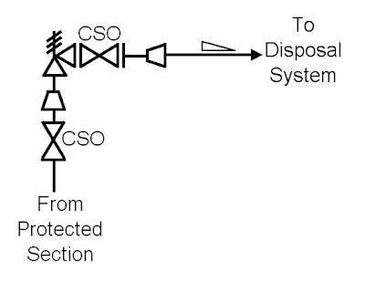
Blocked valves are normally provided upstream and downstream of Pressure Relief Valve for isolation purpose during maintenance, inspection, etc. You may noticed a word "CSO" or "CSC" attached to the block valve. What is CSO and CSC ? What is the purpose ?
Above question has been raised by some very fresh engineers in several times and i think it is worth to discuss here.
What is CSO and CSC ?
"CS" stand for Carseal while "O" and "C" are stands for Open and Close respectively. This is pretty simple.
How "Carseal" term was originated ?
The term "carseal" comes from the railroad industry. Railcars were loaded with goods. To assure that the goods were not tampered with, agents on the shipping end would but a wire though a hole in the handle and then through a hole in the car. They would then use a lead ball with a hole in it that each end of the wire was put through. A hand press would be used to squeeze the lead tight on the wires and imprint a a seal of the agency. If the wire where cut or the seal was broken, they knew the shipment was tampered with. Latter versions used stainless steel bands with serial numbers and codes on them.
What is the function of Carseal ?
In a process plant, some of block valves shall be put in a fix position for specific reason. For example, a drain block valve is Carseal Closed (CSC) to avoid loss of inventory in the event of inadvertently opening of this valve. This CSC valves can assist operator easily identify those valves position can only be altered with specific permission via stringent control procedure. Similarly, pressure relief valve inlet and outlet isolation valves are Car Sealed Open (CSO) to avoid operator inadvertently close.
How Carseal is implemented in a valve ?
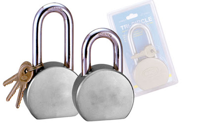
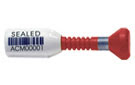
Nowadays, most (if not all) valve manufactures will have hole cut in valve handles and tabs on the valve bodies. Some valve manufactures will treat this as additional feature by providing a "add-on" adapter with in-built hole. These holes can be lined up and cable seal, plastic / metal strips, etc. Following are some images for different seal type.
Carseal enhance safe operational of a plant. For safeguarding purpose, a higher safety devices e.g locked open, key interlocked, etc shall be used.
Related Post
How "Carseal" term was originated ?
The term "carseal" comes from the railroad industry. Railcars were loaded with goods. To assure that the goods were not tampered with, agents on the shipping end would but a wire though a hole in the handle and then through a hole in the car. They would then use a lead ball with a hole in it that each end of the wire was put through. A hand press would be used to squeeze the lead tight on the wires and imprint a a seal of the agency. If the wire where cut or the seal was broken, they knew the shipment was tampered with. Latter versions used stainless steel bands with serial numbers and codes on them.
What is the function of Carseal ?
In a process plant, some of block valves shall be put in a fix position for specific reason. For example, a drain block valve is Carseal Closed (CSC) to avoid loss of inventory in the event of inadvertently opening of this valve. This CSC valves can assist operator easily identify those valves position can only be altered with specific permission via stringent control procedure. Similarly, pressure relief valve inlet and outlet isolation valves are Car Sealed Open (CSO) to avoid operator inadvertently close.
How Carseal is implemented in a valve ?
Nowadays, most (if not all) valve manufactures will have hole cut in valve handles and tabs on the valve bodies. Some valve manufactures will treat this as additional feature by providing a "add-on" adapter with in-built hole. These holes can be lined up and cable seal, plastic / metal strips, etc. Following are some images for different seal type.
Heavy Duty Bolt Lock
Can only be cut by special cutting tools...
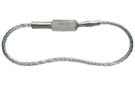
Cable Seal

Plastic Seal
Can only be cut by special cutting tools...
Cable Seal
Plastic Seal
Carseal enhance safe operational of a plant. For safeguarding purpose, a higher safety devices e.g locked open, key interlocked, etc shall be used.
Related Post
- Locked Valve Increases Security, Reliability & Integrity
- Parallel Valve Technology Increase Safety & Reduce Nuisance Trips
- Extra Caution When Eliminating Overpressure by Fire Attacks
- PSV for Shell-and-Tube HEX Tube Side Overpressure Protection against External Fire Attack ?
- Practical Measures to Eliminate or Avoid HX Tube Rupture Scenarios
- Tube Rupture : Pressure Relief Valve (PSV) or Rupture Disk (RD) ?
Labels: Pressure Relief Device, Safety
Wednesday, April 16, 2008
Display problem ? Click HERE

Just a quick update to IEM members...
I received a notification from IEM that the AGM 2008 will be held on 19 April 2008. at Ingenieur building. Annual report is available HERE or HERE...
Tuesday, April 15, 2008
Display problem ? Click HERE
Pressure Relief Valve (PRV) discharge to a tail pipe, subheader, header, flare knock-out drum and subsequently flare to atmosphere. All of above collective called flare collection and disposal system. One of the phenomenon potential results catastrophic failure of flare system is the hydrate formation or icing in any part of flare collection system.

How hydrate and ice form in the flare collection system ?
There are two scenarios where hydrate or ice can form in the flare collection system. First scenario, when process fluid at high pressure and low temperature passing the PRV, Joule-Thompson (JT) effect results low temperature at downstream of PRV. As the temperature lower than the process fluid hydrate formation or icing temperature, crystal form hydrate or ice will form. Second scenario, when cold and dry relieving fluid mix with warm and wet relieving fluid the mixing temperature drops below mixture hydrate formation or icing temperature.
Once hydrate, it will find a surface to stick on and it will form "nucleus" to stick on it. The hydrate size is gradually increase and it potentially of completely blocking the pipe.
Will Hydrate or Ice formed in Flare system practically ?
Having said that hydrate or ice may form once the condition is right, however, it is unlikely to see hydrate or ice formation in flare header. The reasons could be :
i) As the PRV discharge is normally limited to some period and not sustainable, the discharge inventory (hydrate former) may not sufficient to completely block a large flare line.
ii) PRV discharging fluid at very high velocity. High gas momentum sweep away hydrate or ice formed.
iii) Flare piping is "hot" and contain heat which sufficient to destroy the hydrate or ice stick on it
Good engineering practices to minimize potential of catastrophic failure cause by hydrate or ice formation
No doubt the potential of hydrate or ice formation in flare collection system is low, however, it still remain a high risk cause. Good engineering practices shall be incorporated to minimize the possibility of hydrate or ice formation.
i) Segregate warm & wet fluid with cold & dry fluid into different headers.
ii) Avoid small PRV discharge tail pipe
iii) Make short piece between PRV outlet flange and expander
iv) Minimise elbow and tee before tail pipe end at large subheader
v) Increase reliability of high pressure tripping system to minimise relief events
PRV leaks results Hydrate or Ice formed
PRV leaking or passing is one the phenomenon that very difficult to avoid. Whenever PRV passing, hydrate or ice still potentially form at PRV outlet due to small opening and prevent the PRV to open. In this case, high reliability and availability heat tracing (e.g. High SIL loop, connected to emergency power supply, etc) may be considered to ensure the PRV temperature is maintained above hydrate or ice formation temperature.
Coldness from fluid potentially transfer to the PSV vent chamber and the moisture content in the PSV chamber may potentially friezed and preventing the PRV to open. Piston balanced PRV may be considered in this particular case.
Related Post
- Hydrate formed Downstream of PRV ?
- PSV for Shell-and-Tube HEX Tube Side Overpressure Protection against External Fire Attack ?
- Practical Measures to Eliminate or Avoid HX Tube Rupture Scenarios
- Parallel Valve Technology Increase Safety & Reduce Nuisance Trips
- Two-third (2/3) rule or Ten-thirteen (10/13) rule ?
Labels: Overpressure Protection, Pressure Relief Device
Sunday, April 13, 2008
Display problem ? Click HERE
Simple update to IEM Members or those who are practicing Engineering in MALAYSIA, IEM IT Special Interest group is organizing a "Standards Development in Malaysia" (BEM Approved).
Date : 22nd April 2008, TuesdayRelated Post
Time : 5.30 pm to 7.30 pm
Venue : 2nd Floor, IEM Conference Hall, Bangunan Ingenieur, Petaling Jaya
Speaker : Mr.Hussalmizzar bin Hussain
CPD/PDP HOUR : 2
Ref No: IEM08/HQ/095/TThis talk will discuss briefly about Standards development associates with development of a nation, the Standards Development monitoring programes of Ministry of Science, Technology and Innovation (MOSTI).
The talk will cover the following topics in a little details :
1. Standards of Malaysia Act 1996
- Key provisions
- Definition of Standards
- Roles of the parties involved in the development of standards
2. Operationalising the development of standards
- Standards Committees (ISCs)
- Terms of Reference
- Membership of ISCs
- Standards Technical Committee and Working Committees (ISC/TC/WG) setup
- Consensus/voting mechanism
3. Finalising and Approval of standards
- Public feedback
- ISC Review/Endorsement
- Minister approval and gazette
4. Promotion of standards
5. ISC G and ICT related standards development activities
- News related to IEM in 2008...
- Time to renew your registration as PE...
- Practicing Engineering & Route To Professional Engineer in MALAYSIA
- Seek Opinions on RESOURCE section...
- R&D engineer, Academician and Student...Don't miss this !
Friday, April 11, 2008
Display problem ? Click HERE
CO2 known as one of main contributor to global warming and greenhouse effect. Nowadays, CO2 sequestration and re-injection into disposal well is one of the common way to reduce CO2 emission into atmosphere. In earlier post Several Concerns in High CO2 Field Development, one of the effort taken was to separate CO2 from well gas and re-inject it back to disposal well.

Another direction in reducing CO2 emission to atmosphere is to convert CO2 to useful and valuable product. Sandia’s Sunshine Laboratory has invented a prototype device called the Counter Rotating Ring Receiver Reactor Recuperator (CR5), breaks carbon-oxygen (C-O) bonds in carbon dioxide (CO2) to form carbon monoxide (CO) and oxygen (O) in two steps. Water (H2O) and carbon monoxide (CO) will then produce methanol, gas, or other liquid fuels using solar energy. Read more in Sandia’s Sunshine to Petrol project seeks fuel from thin air.
Above effort no only reduce CO2 emission, it also reduce the demand of energy from well crude or gas. Nevertheless, there are still some "issue" needs to be resolved before it can be used as a workable alternative. Issues are :
Is overall process''s energy efficiency low ?It is believed that new invention always encounter disagreement and challenges from all parties with whatsoever reasons, however, the effort and objective behind this project shall be praised and appreciated.
Is overall energy effective ?
Operational ?
.
.
Related Topic
- Methane Conversion Challenge
- Several Concerns in High CO2 Field Development
- Use Ultra-Sonic Flowmeter in FLARE Gas Header for emission monitoring
- How does Supercritical fluid looks like ?
Labels: CO2, Global warming, Greenhouse Effect
Thursday, April 10, 2008
Display problem ? Click HERE
Vaccum hazard is potentially a hazard and damaging factor to many pressure vessel. Vacuum should be addressed and extra caution to be taken during design, construction, operation and maintenance to avoid catastrophic failure. Following are four (4) steps approach to combat vacuum hazard.
Avoid it
This is the first principle to be adopted in any design and operation. System shall be designed and operating procedures shall be implemented to avoid the occurrence of vacuum condition in a vessel.
Whenever there is a potential of vacuum can be created, an automatic control system may be implemented to prevent it from occur. Some typical control system could be
Whenever the control system as mentioned in earlier section can not prevent it to happen, provide a high level shutdown system to stop continuous further creation of vacuum. Typically a highly reliable low-low pressure trip is provided to stop a external mechanical driver to continue operate e.g. stop reciprocating pump which is drawing water from a vessel.
Protect it- Vessel to be kept pressurized during cooling until the vessel and it contents cooled to ambient temperature.
- Vessel to be purged with inert gas prior to any cooling cycle
Whenever there is a potential of vacuum can be created, an automatic control system may be implemented to prevent it from occur. Some typical control system could be
- Inert gas blanketing system to maintain positive pressure in the vessel
- Continuous purging system in the flare header
- Application of insulation layer to avoid sudden heat loss to ambient
Whenever the control system as mentioned in earlier section can not prevent it to happen, provide a high level shutdown system to stop continuous further creation of vacuum. Typically a highly reliable low-low pressure trip is provided to stop a external mechanical driver to continue operate e.g. stop reciprocating pump which is drawing water from a vessel.
This is the last resource but shall be implemented whenever a risk of vacuum is identified and present.The main concept is provide a system or device to sustain or break the vacuum whenever it occurred.
Related Post
- Design the system for FULL VACUUM
Full vacuum (FV) — a condition where the internal absolute pressure is 0 psi (0 KPa) and the external absolute pressure on the vessel is 15 psi (100 KPa).
- Provide Pressure-Vacuum-Relief-Valve (PVRV) to break vacuum in case it occurred.
- May consider to provide liquid seal as vacuum breaker
Related Post
- Vacuum Hazard - Another Catastrophic Factor...
- Parallel Valve Technology Increase Safety & Reduce Nuisance Trips
- Dust Explosion Basic & Protection
- Why not bury flare pipe header ?
- Extra Caution When Eliminating Overpressure by Fire Attacks
- Blast rocks Texas oil refinery
- Petrol Kiosk - Some Thought and Advices...
- Design fault in Hydrogen Attack of Residue Hydrodesulfurrization
Wednesday, April 9, 2008
Display problem ? Click HERE
Benoy in his early thread " Vacuum For Pressure Vessel Design" has triggered to think a little more on an old subject "Vacuum Hazard".
What is Vacuum Hazard ?
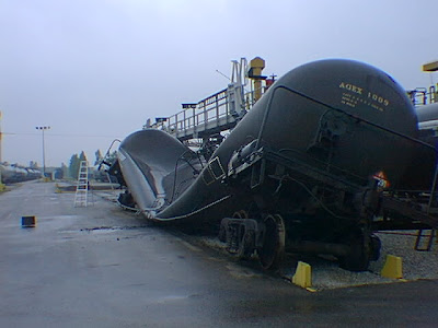
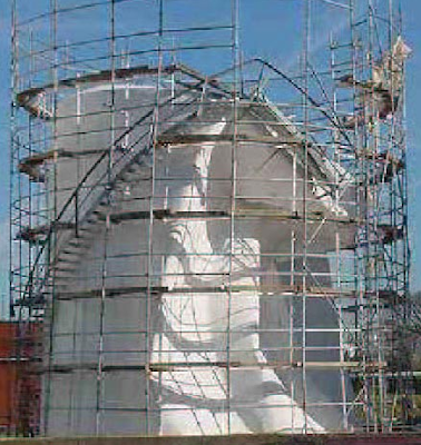
Vacuum or negative pressure can be dangerous and damaging to vessel as many vessel structures may not be built to withstand reversed stresses caused by negative pressure or vacuum. Following images show vessel collapsed caused by Vacuum.
What are the main factors resulting Vacuum ?
TWO main factors are potentially the best candidates result Vacuum in a vessel. There are External mechanical draw and Internal contraction.
Several scenario you may have to consider potential of Vacuum Hazard
i) Vessel containing fluid with vapor pressure at minimum ambient temperature lower than atmospheric. Typical example is the steam-condensate system. A steam drum shut down and cool down normal ambient cooling. As the steam cooled, it will start to condense and condensation lead to sudden volume contraction and this potential causing partial vacuum condition in the steam drum. Main factor is internal contraction due to heat loss.
ii) Atmospheric tank storing hot liquid. Similarly external cooling would cause liquid contraction and lead to partial vacuum in the tank. Main factor is internal contraction due to heat loss.
iii) Gravity draining of vessel filled with low vapor pressure (VP) liquid (i.e. water). Draining of low VP liquid out from vessel (completely blocked) would results negative pressure or partial vacuum in the vessel due to liquid column. Main factor is external mechanical draw by gravity force.
iv) Reciprocating pump drawing low VP liquid from vessel. Reciprocating pump continue drawing liquid from vessel would also lead to vacuum in the vessel. Again, the main factor is external mechanical draw by mechanical force.
v) Hot Relief into Flare Header. After a hot gas relief into the flare header, the hot gas in the header will be cooled by ambient. This would be accelerated with raining, snowing, winter, etc. Again, hot gas cooling may result condensation and potential create partial vacuum in the flare header. Main factor is internal contraction due to heat loss.
vi) Blocked Vent line. Bird nest or plastic in the vent line would partially or completely blocked the vent line. This potentially causing partial vacuum in the tank when the tank is cooled or pump-out. Main factor could be internal contraction due to heat loss or external mechanical draw by mechanical force.
Thus, vacuum may be a hazard and damaging factor to your system. It shall be addressed and extra caution to be taken during design, construction, operation and maintenance to avoid catastrophic failure.
Click to read 4-steps Approach to Combat Vacuum Hazard ...
Related Post
WebWorm
What are the main factors resulting Vacuum ?
TWO main factors are potentially the best candidates result Vacuum in a vessel. There are External mechanical draw and Internal contraction.
- External mechanical draw
This factor basically cause by a external mechanical force to draw mass in the vessel out and creating vacuum in the vessel. Typical example are vacuum compressor, steam ejector, etc.
- Internal Contraction
Temperature different results internal heat is forced to transmit out from the vessel and internal fluid experience sudden contraction due to condensation. Typical example is steam-condensate drum.
Several scenario you may have to consider potential of Vacuum Hazard
i) Vessel containing fluid with vapor pressure at minimum ambient temperature lower than atmospheric. Typical example is the steam-condensate system. A steam drum shut down and cool down normal ambient cooling. As the steam cooled, it will start to condense and condensation lead to sudden volume contraction and this potential causing partial vacuum condition in the steam drum. Main factor is internal contraction due to heat loss.
ii) Atmospheric tank storing hot liquid. Similarly external cooling would cause liquid contraction and lead to partial vacuum in the tank. Main factor is internal contraction due to heat loss.
iii) Gravity draining of vessel filled with low vapor pressure (VP) liquid (i.e. water). Draining of low VP liquid out from vessel (completely blocked) would results negative pressure or partial vacuum in the vessel due to liquid column. Main factor is external mechanical draw by gravity force.
iv) Reciprocating pump drawing low VP liquid from vessel. Reciprocating pump continue drawing liquid from vessel would also lead to vacuum in the vessel. Again, the main factor is external mechanical draw by mechanical force.
v) Hot Relief into Flare Header. After a hot gas relief into the flare header, the hot gas in the header will be cooled by ambient. This would be accelerated with raining, snowing, winter, etc. Again, hot gas cooling may result condensation and potential create partial vacuum in the flare header. Main factor is internal contraction due to heat loss.
vi) Blocked Vent line. Bird nest or plastic in the vent line would partially or completely blocked the vent line. This potentially causing partial vacuum in the tank when the tank is cooled or pump-out. Main factor could be internal contraction due to heat loss or external mechanical draw by mechanical force.
Thus, vacuum may be a hazard and damaging factor to your system. It shall be addressed and extra caution to be taken during design, construction, operation and maintenance to avoid catastrophic failure.
Click to read 4-steps Approach to Combat Vacuum Hazard ...
Related Post
- 4-steps Approach to Combat Vacuum Hazard
- Parallel Valve Technology Increase Safety & Reduce Nuisance Trips
- Dust Explosion Basic & Protection
- Why not bury flare pipe header ?
- Extra Caution When Eliminating Overpressure by Fire Attacks
- Blast rocks Texas oil refinery
- Petrol Kiosk - Some Thought and Advices...
- Design fault in Hydrogen Attack of Residue Hydrodesulfurrization
WebWorm
