Wednesday, August 29, 2007
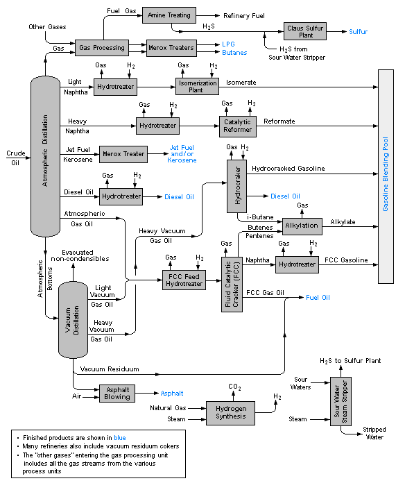
Labels: Refinery
Tuesday, August 28, 2007
 pitting resistivity of particular metal and alloy compare to the other ? Pitting Resistance Equivalent Number is used.
PREN can be calculated , using the alloy chemical composition, to estimate relative pitting resistance of metal and alloys.
PREN = %Cr + m.(%Mo) + n.(%N)
PRE = % Cr + 3.3 (% Mo)
For austenitic grades Stainless Steel, the formula employed is :
PREN = %Cr + 3.3(%Mo) + 30(%N)
PREN = %Cr + 3.3(%Mo) + 16(%N)
PREN = %Cr + 1.5(%Mo + %W + %Nb)
Related topics
Labels: Corrosion, Corrosion Resistance Material, Pitting
Sunday, August 26, 2007

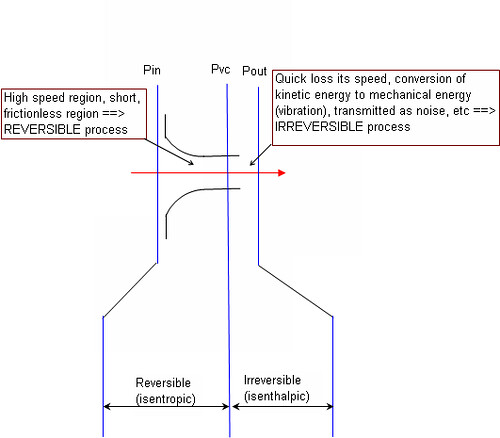
Labels: Modelling, Pressure Relief Device, PSV, Thermodynamic
Saturday, August 25, 2007

You have heard about Floating Production Storage Offloading (FPSO) unit...you have heard about Floating LNG Unit...have you ever heard about Floating Gas Refinery Unit ?
Read HERE...
Friday, August 24, 2007

Pitting Corrosion on Metal Surface
Pitting can occur in any metal surfaces. Following are some pictures of pitting corrosion.


Co2 Pitting corrosion on internal pipe surface

Severity of pitting corrosion
Knowing that pitting can cause failure due to perforation while the total corrosion, as measured by weight lossm might be rather minimal, experience shown that rate of penetration may be 10 to 100 times that by general corrosion, pitting corrosion has been considered to be more dangerous than the uniform corrosion damage because it is very difficult to detect, predict and design against. General metal weight loss method almost impossible to detect the internal pitting corrosion.
Pitting corrosion shape
Pits formed due to pitting corrosion can become wide and shallow or narrow and deep which can rapidly perforate the wall thickness of a metal. Following picture demonstrate several types of pitting corrosion shape. This has made it even more difficult to be detected especially undercutting, subsuface and horizontal type.

Preventive measures
There are several preventive approah to avoid pitting. There are :
- Proper material selection e.g. SS316 with molydenum having higher pitting resistance compare to SS304
- Use higher alloys (ASTM G48) for increased resistance to pitting corrosion
- Control oxygen level by injecting oxygen scavenger in boiler water system
- Control pH, chloride concentration and temperature
- Cathodic protection and/or Anodic Protection
- Proper monitoring of oxygen & chloride contents by routine sampling
- Agitation of stagnant fluid
- Chloride stress corrosion cracking and use of correct MOC for seawater
- How Chloride stress corrosion cracking Lookslike ?
- Unified Numbering System for Metals and Alloys
Labels: Corrosion, Corrosion Resistance Material, Material, Pitting
Thursday, August 23, 2007
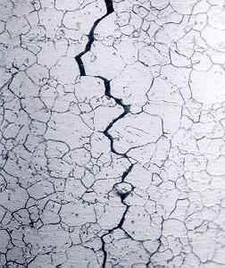
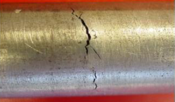
The following are some images of metal experienced Chloride Stress Corrosion Cracking.
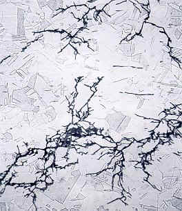
Inter granular SCC of an Inconel heat exchanger tube
Trans granular SCC of 316 stainless steel chemical processing piping system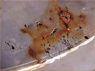
CSCC occured on insulated vessel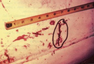
CSCC occured on insulated vessel
CSCC occured on Condenser tube
CSCC on pipe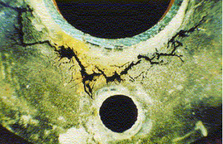
Inter granular SCC of a pipe
Related Topics
- Chloride stress corrosion cracking and use of correct MOC for seawater
- Unified Numbering System for Metals and Alloys
Labels: Chloride Stress Corrosion Cracking, Corrosion, Corrosion Resistance Material, Material
Wednesday, August 22, 2007

Factors that influence the rate and severity of cracking include
- chloride content
- oxygen content
- temperature
- stress level
- pH value of an aqueous solution
It has been established that oxygen is required for CSCC to occur. Detail may refer to HERE.
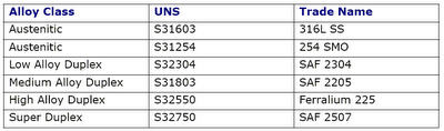
The severity of cracking increases with temperature. Figure below shows several Stainless Steel materials increases it susceptibility to CSCC as temperature is increased.

SAF 2205 (UNS 31803) = Duplex Stainless Steel
SAF 2507 (UNS 32750) = Super Duplex Stainless Steel
Material under pressure without Post weld heat treatment will experience high stress level. Higher the stress level, higher the potential of CSCC.
Acidic process(low pH) with chloride content in it tends to increase the CSCC potential.
CASE STUDIES
Eventhough the inlet and outlet temperature are below 150 degC, thermal designer may design the heat exchanger with high heat flux in order to reduce the heat exchanger area and this result tube skin temperature exceeded 150 degC. Condition with Seawater which contains ~20,000 mg/l Chloride, high in dissolved oxygen, slightly acidic and skin temperature exceeded 150 degC is perfect combination conditions for CSCC to occur for DSS. Those heat exchanger designer shall always check skin temperature profile especially for low flow condition or specify better material i.e. Super DSS for above service.
Further Reading
Labels: Chloride Stress Corrosion Cracking, Corrosion Resistance Material, Material
Tuesday, August 21, 2007
 What are the differences between Duplex Stainless Steel, Medium Alloy Duplex, 22% Cr, SAF 2205 and UNS 31803 ?
- UNS number
- Description
- Common trade names and alloy designations
- Cross-reference organization
- Cross-reference specifications
- Chemical composition
The UNS is managed jointly by the American Society for Testing and Materials (ASTM) and the Society of Automotive Engineers (SAE).
The UNS number (for "Unified Numbering System for Metals and Alloys") is a systematic approach where each metal is designated by a LETTER followed by five NUMBERS. The number is unique and composition-based of commercial materials. It is used for material reference but it does not guarantee any performance specifications and/or exact composition.
Following are overview of common commercial metals / alloys using UNS system :
- Axxxxx - Aluminium Alloys
- Cxxxxx - Copper Alloys, including Brass and Bronze
- Fxxxxx - Iron, including Ductile Irons and Cast Irons
- Gxxxxx - Carbon and Alloy Steels
- Hxxxxx - Steels - AISI H Steels
- Jxxxxx - Steels - Cast
- Kxxxxx - Steels, including Maraging, Stainless, HSLA, Iron-Base Superalloys
- L5xxxx - Lead Alloys, including Babbit Alloys and Solders
- M1xxxx - Magnesium Alloys
- Nxxxxx - Nickel Alloys
- Rxxxxx - Refractory Alloys
- R03xxx- Molybdenum Alloys
- R04xxx- Niobium (Columbium) Alloys
- R05xxx- Tantalum Alloys
- R3xxxx- Cobalt Alloys
- R5xxxx- Titanium Alloys
- R6xxxx- Zirconium Alloys
- Sxxxxx - Stainless Steels, including Precipitation Hardening and Iron-Based Superalloys
- Txxxxx - Tool Steels
- Zxxxxx - Zinc Alloys
Typical example :
Relating Topics
- Chloride stress corrosion cracking and use of correct MOC for seawater
- How Chloride stress corrosion cracking Lookslike ?
Labels: Corrosion Resistance Material, Material, UNS
Monday, August 20, 2007
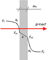
Basic heat transfer relationships is apply to Air-Cooled Heat Exchanger (ACHE) . The fundamental heat transfer equation :
U = overall heat transfer coefficient
A = Heat transfer area
LMTD = Log mean temperature difference
F = Correction factor
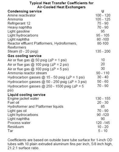
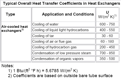
Typical heat transfer coefficient for Air-Cooled Heat Exchangers
Further Reading
Labels: Air Cooler, Heat Exchanger, Heat Transfer
Sunday, August 19, 2007

ii) On-off fan operation (manual)
iii) Two-speed fans (manual or automatic)
iv) Louvers or shutters (automatic)
v) Variable pitch fans (automatic)
vi) Variable speed fans (automatic)
Labels: Air Cooler, Fan, Heat Exchanger
Saturday, August 18, 2007

Further reading
Labels: Air Cooler, Fan, Heat Exchanger
Friday, August 17, 2007

Tuf-Lite
Axial Flow Fans for Air Cooled Heat Exchanger & Cooling tower from HUDSON Product Incorporation (HPC)
Further reading
Labels: Air Cooler, Fan, Heat Exchanger
Thursday, August 16, 2007

Apart from FREE software for download, HUDSON also share other very useful articles in it website...
Basic of Air-Cooled Heat Exchanger (ACHE)
Other very useful articles available for FREE download in HUDSON website are :
Further Reading
Labels: Air Cooler, Fan, Heat Exchanger
Tuesday, August 14, 2007

- Fin-Fan ® Air-Cooled Heat Exchangers
- Hy-Fin ® Extruded Finned Tubing
- Tuf-Lite ® FRP Axial Flow Fans for air coolers and cooling towers.
- Tuf-Lite I I® FRP Axial Flow Fans for air coolers and cooling towers.
- Basics of Air-Cooled Heat Exchangers - This software is designed to familiarize users with the types, components, and features of air-cooled heat exchangers.
- Fan-Rating Program - The Tuf-lite Fan Selection Program is designed to assist customers in selecting the appropriate axial flow fan for their application.
Further reading
Labels: Air Cooler, Fan, Heat Exchanger
Monday, August 13, 2007

Most of us may already aware of the answer. Pressure drop will increase.
Reason being,
"The OD of the pipe is basically fixed (+ or -) but as you have already determined, the schedule number is related to the thickness, with the higher numbers indicating thicker pipe, smaller pipe ID and therefore a smaller cross sectional area of the flow path. A 2" pipe has a fairly constant OD of 2.375". The 2" schedule 40 pipe has an ID of 2.067" but a 2" schedule 160 pipe has an ID of 1.687". Obviously the schedule 160 pipe has a smaller flow path than does the schedule 40 pipe and thus for your example the velocity (and pressure drop) will be greater in the schedule 160 pipe.", by Phil LECKNER.
The post has triggered me to create some handy links...
NPS - "Nominal Pipe Size" and DN - "Diametre Nominel"
The size of pipes, fittings, flanges and valves are often given in inches as NPS - Nominal Pipe Size, or in metric units as DN - "Diametre Nominel"
Pipe Equations
Calculate cross-sectional area, weight of empty pipes, weight of pipes filled with water, inside and outside surface area
m = 10.68 (do - tw) tw
where
m = weight per foot (lbs/ft)
do = outside diameter (inches)
tw = wall thickness (inches)
Friday, August 10, 2007

Another phenomenon which common understood by everyone is that as the backpressure is increased, additional force apply on the PSV disc and reduce disc lift, it reduce discharge capability. This clearly explained in figure 22 in API RP 521 Part-I.

However, the impact is insignificant at low backpressure. API 521 Part-I has recommended that in a conventional PSV application, built-up backpressure SHOULD NOT exceed 10% of the set pressure at 10% allowable overpressure (refer 3.3.3.1.3.). This statement is recommendation instead of mandatory requirement per API. Those conventional type PSV still can be used if the built backpressure > 10% of set pressure for specific events and selected PSVs.
A studies <<Back pressure effects on safety valves operating with compressible flow>>, conducted by Vincenzo Dossena has clearly proved above statement.
This report has showed that
i) ratio of measured discharge coefficient (Kd,m) and theoretical discharge coefficient (Kd,t) (at 10% overpressure) is in the range of 0.95 to 1.02 at 10% built-up backpressure
ii) ratio of measured discharge coefficient (Kd,m) and theoretical discharge coefficient (Kd,t) (at 10% overpressure) maintain at / above 1 for some PSVs at >10% built-up backpressure
Point (i), with the minimum ratio of 0.95, normal Kd factor for PSV is 1, the actual Kd may be conservatively 0.95.
API 520 Part-I has recommended Kd factor of 0.975. SHELL DEP has taken conservative approach where Kd factor of 0.9 to be used.
Point (ii), this implies that conventional PCV may be used even the back pressure is exceeded 10% built-up back pressure. Designer/engineer shall take EXTRA attention if conventional PSV is used when the back pressure > 10% set pressure and shall always seek advice & confirm with PSV vendor.
Reference :
i) API RP 520 Part-I, Sizing, Selection and Installation of Pressure Relieving Devices in Refineries, Seven Edition, an 2000
ii) Vincenzo Dossena, “Back pressure effects on safety valves operating with compressible flow”, published in VALVE WORLD.
Labels: Pressure Relief Device, PSV
