Friday, April 4, 2008
Display problem ? Click HERE
A Shell & Tube heat exchanger potentially expose to the risk of internal failure results a complete tube rupture. Read Criteria for Requirement of Pressure Relief Device for Tube Rupture for criteria lead to tube rupture. In determining the required relieving flow rate, API Std 521 - ISO 23251, Fifth edition, Jan 2007, "Pressure-relieving and Depressuring Systems ", section 5.19.3. can be referred
5.19.3 Determining the required relief flow rateIn practice, an internal failure can vary from a pinhole leak to a complete tube rupture. For the purpose of determining the required relieving flow rate for the steady-state approach, the following basis should be used.a) The tube failure is a sharp break in one tube.
b) The tube failure is assumed to occur at the back side of the tubesheet.
c) The high-pressure fluid is assumed to flow both through the tube stub remaining in the tubesheet and through the other longer section of tube.A simplifying assumption of two orifices may also be used in lieu of the above method, since this produces a larger relief flow rate than the above approach of a long open tube and tube stub.
How to determine a maximum area for relieving flow in Plate & Frame heat exchanger (PHE) which is having rather different structure in construction ?
A Plate & Frame Heat Exchanger is constructed by putting many corrugated plates together likes a sandwich and allowing fluids passing the channels (opening area between plate). Hot and cold will take the channel between plate in "sandwich" format e.g. first channel is hot fluid in upward direction, second channel is cold fluid in downward direction, third channel is hot fluid in upward direction again, etc... Detail may refer HERE...
Cross sectional view of the plate heat exchanger is as follow.
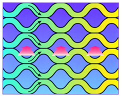
Refer to following image.
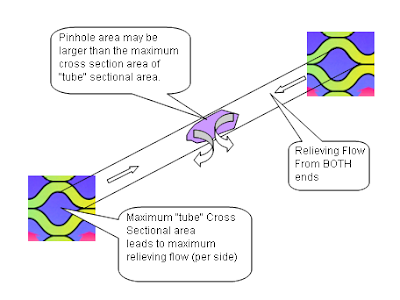
From above limit, maximum relief flow shall be taken as equivalent to the leakage rate through a pinhole of a cross sectional area equal to twice the maximum area of a "tube" cross sectional area. This maximum "tube" cross sectional area may be advised by PHE vendor.
Related Topic
A Plate & Frame Heat Exchanger is constructed by putting many corrugated plates together likes a sandwich and allowing fluids passing the channels (opening area between plate). Hot and cold will take the channel between plate in "sandwich" format e.g. first channel is hot fluid in upward direction, second channel is cold fluid in downward direction, third channel is hot fluid in upward direction again, etc... Detail may refer HERE...
Cross sectional view of the plate heat exchanger is as follow.
Refer to following image.
From above limit, maximum relief flow shall be taken as equivalent to the leakage rate through a pinhole of a cross sectional area equal to twice the maximum area of a "tube" cross sectional area. This maximum "tube" cross sectional area may be advised by PHE vendor.
Related Topic
- Complicated Tube Rupture Scenario... Nightmare in Sizing a PRD
- Two-third (2/3) rule or Ten-thirteen (10/13) rule ?
- Tube Rupture : Pressure Relief Valve (PSV) or Rupture Disk (RD) ?
- Criteria for Requirement of Pressure Relief Device for Tube Rupture
- Requirement of Overpressure Protection Device on "Final Vessel"
- FREE & Reliable Pressure Relief Valve Sizing Software
- Extra Caution When Eliminating Overpressure by Fire Attacks
- Should maximum recommended wall temperature (Tw) for carbon steel vessel used as design temperature ?
- Should we install Butterfly valve for Pressure Relief Valve (PSV) isolation ?
Labels: Heat Exchanger, Overpressure Protection, PHE, Plate Heat Exchanger
posted by Webworm, 4:40 PM


0 Comments:
Post a Comment
Let us know your opinion !!! You can use some HTML tags, such as <b>, <i>, <a>
Subscribe to Post Comments [Atom]
Home:
<< Home