Wednesday, August 20, 2008

As the price of electricity, natural gas and other fossil fuels continues to climb, chemical processors are more closely examining high-temperature operations and heat-transfer systems to see if more efficiency can be had. In many cases
it can, and, as a result, heat-transfer projects are not only justifiable, but downright attractive.
There was a dialog among a few heat exchanger specialist from Alfa Laval, Paul Muller, Exergy LLC, etc. The dialog mainly discussed on strategy to improve heat transfer efficiency, heat recovery and efficient process control during this high energy price arena.
A few tips have been present :
- The energy crisis results high prices all of the time shorten paybacks. Energy efficient is one of the way to minimize cost
- Energy efficient heat transfer equipment such as Plate Heat exchanger, Gasketed Heat exchanger, Bonded Heat exchanger, etc is one of the option.
- For a service using Shell & Tube (S&T), the overall heat transfer coefficient (HTC) is around 300 Btu/h ft2°F. However, the overall heat transfer coefficient (HTC) for a compact heat exchanger can be improved 3-4 times (~1000 to 12000 Btu/h ft2°F).
- With lower overall heat transfer coefficient, this may translate into less space, smaller installation and handling cost. Capital cost may not be low as the fabrication cost for compact heat exchanger is high.
- Gasketed Heat exchanger good for maintenance. However shall take additional attention on the compatibility between gasket and fluid.
- All welded or Bonded heat exchanger may be considered if there is gasket & fluid compatible problem
- For laminar flow, heat transfer rate is only the function of fluid thermal conductivity. Operate heat transfer equipment at lamina flow during turndown could significantly reduce it heat transfer rate
- Compact heat exchanger promote turbulence. High turbulence increase heat transfer rate and reduce fouling (read more)
- Thus plant releasing hot exhaust gas from burner, boiler, gas turbine, etc to atmosphere may take the opportunity to recover heat
- Improve temperature control in process system would reduce energy usage
Not a CE subscriber... click here to subscribe FREE Chemical Engineering (CE)
Related Topic
- Practical Design Tips for Heat Exchanger Design
- COMPACT Heat Exchanger Increased Performance, Optimised area utilization, reduce CAPEX & OPEX
- Unexpected high cost of heat exchanger fouling...
- CFD in Compact Heat Exchanger
- Heat Transfer - Internal and External Flow
- Why Lower Fouling in Plate Heat Exchanger ?
Labels: Compact heat Exchanger, Heat Exchanger, Heat Recovery, Heat Transfer, Plate Heat Exchanger
Friday, April 4, 2008
A Shell & Tube heat exchanger potentially expose to the risk of internal failure results a complete tube rupture. Read Criteria for Requirement of Pressure Relief Device for Tube Rupture for criteria lead to tube rupture. In determining the required relieving flow rate, API Std 521 - ISO 23251, Fifth edition, Jan 2007, "Pressure-relieving and Depressuring Systems ", section 5.19.3. can be referred
5.19.3 Determining the required relief flow rateIn practice, an internal failure can vary from a pinhole leak to a complete tube rupture. For the purpose of determining the required relieving flow rate for the steady-state approach, the following basis should be used.a) The tube failure is a sharp break in one tube.
b) The tube failure is assumed to occur at the back side of the tubesheet.
c) The high-pressure fluid is assumed to flow both through the tube stub remaining in the tubesheet and through the other longer section of tube.A simplifying assumption of two orifices may also be used in lieu of the above method, since this produces a larger relief flow rate than the above approach of a long open tube and tube stub.
A Plate & Frame Heat Exchanger is constructed by putting many corrugated plates together likes a sandwich and allowing fluids passing the channels (opening area between plate). Hot and cold will take the channel between plate in "sandwich" format e.g. first channel is hot fluid in upward direction, second channel is cold fluid in downward direction, third channel is hot fluid in upward direction again, etc... Detail may refer HERE...
Cross sectional view of the plate heat exchanger is as follow.
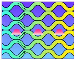
Refer to following image.
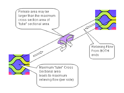
From above limit, maximum relief flow shall be taken as equivalent to the leakage rate through a pinhole of a cross sectional area equal to twice the maximum area of a "tube" cross sectional area. This maximum "tube" cross sectional area may be advised by PHE vendor.
Related Topic
- Complicated Tube Rupture Scenario... Nightmare in Sizing a PRD
- Two-third (2/3) rule or Ten-thirteen (10/13) rule ?
- Tube Rupture : Pressure Relief Valve (PSV) or Rupture Disk (RD) ?
- Criteria for Requirement of Pressure Relief Device for Tube Rupture
- Requirement of Overpressure Protection Device on "Final Vessel"
- FREE & Reliable Pressure Relief Valve Sizing Software
- Extra Caution When Eliminating Overpressure by Fire Attacks
- Should maximum recommended wall temperature (Tw) for carbon steel vessel used as design temperature ?
- Should we install Butterfly valve for Pressure Relief Valve (PSV) isolation ?
Labels: Heat Exchanger, Overpressure Protection, PHE, Plate Heat Exchanger
Wednesday, August 8, 2007
- ECI – Operation & Maintenance Engineers - Don't miss FREE articles (>40) related to HX Fouling & Cleaning (Part 2)
- ECI – Operation & Maintenance Engineers - Don't miss FREE articles (>40) related to HX Fouling & Cleaning (Part 1)
- Do Not Overspecified Fouling Factor s for PHE
- Why Lower Fouling in Plate Heat Exchanger ?
- Heat Exchanger Fouling Mechanism, Prevention and Treatment
 Fouling factor is generally used in the design to cater for heat exchanger deficiency resulted by fouling. TEMA has based on many years of experiences and experiments list out fouling factor for Shell & Tube Heat Exchanger for many services. Only TEMA subscribers are eligible to use this information. However, there are several reputable researchers & manufacturers have shared this information to the public. Following are the collection of fouling factors for different service.
- Engineering page
- Wolverine Tube
- Delta-T
- BayIndustrial
- GEO-center (Plate Heat Exchanger)
If you know some other site contain similar information, please kindly drop a note to me. I will park it here.
Labels: Fouling, Heat Exchanger, Heat Transfer, Plate Heat Exchanger, Shell-and-Tube Heat exchanger
Wednesday, August 1, 2007

Plate Heat Exchanger having narrow channel most probably "not recommended" for fluid contains solid and/or slurry services. However, there are still many success story of using PHE in abovementioned services.
i) 80% of the particles are less than 70% of the interplate gap on the heat exchanger.
ii) 100% of the particles are less than 90% of the interplate gap
iii) Flowing velocity is below erosional velocity (causes premature plate failure)
Further reading
Labels: Heat Exchanger, PHE, Plate Heat Exchanger, Rule-Of-Thumb, Slurry, Solid
Tuesday, July 31, 2007

How do you interprete above question from engineer perspective ?
How do you interprete "fluid handled contains solids" ?
The process may contains solid can be
(a) high concentration, small particle size or;
(b) high concentration, large particle size or;
(c) low concentration, small particle size or;
(d) low concentration, large particle size
PHE is having a very unique feature where narrow channel and proper engineered cross-sectional areas promote turbulence and high heat transfer (convective) capabilities. High turbulence has the potential of removing scale stick on the plate. However, present of solids in fluid promote pluggage in the narrow channel and ultimately results NO flow.

Probably first and ordinary option is relook into the root-cause of under-performed STHE by analyses the STHE construction, review maintenance frequency and methodology, etc and check if there is oppurtunity to modify existing STHE to increase heat exchange performance.
Further reading :
- FAYF - Heat Transfer - Useful Heat Transfer Equation
- Do Not Overspecified Fouling Factor s for PHE
- Why Lower Fouling in Plate Heat Exchanger ?
- Heat Exchanger Fouling Mechanism, Prevention and Treatment
Labels: Heat Exchanger, Plate Heat Exchanger, Slurry, Solid, Spiral Heat Exchanger
Saturday, July 21, 2007

Isn't this approach conservative and guarantee the performance ?
Reason being...
- Oversized Plate Heat Exchanger (PHE) required extra CAPEX and extra Space for oversized PHE
Tubulence minimise fouling tendencies in correctly sized PHE. Oversized PHE results low actual velocity and increase potential fouling and inefficient heat transfer
HTRI studies showed PHE fouling significant lower than Shell & Tube Heat Exchanger (S&T)...factor of 6.7
GUIDELINE : Do not oversized PHE more than 25% against required area.
Further reading :
- Do Not Overspecified Fouling Factor s for PHE
- Why Lower Fouling in Plate Heat Exchanger ?
- Heat Exchanger Fouling Mechanism, Prevention and Treatment
- PHE - Remove some plates, will pressure drop increase ?
Labels: Fouling, Heat Exchanger, PHE, Plate Heat Exchanger
Friday, July 20, 2007

If you plant / maintenance engineers, you probably interested to the following articles...
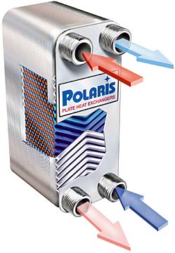
FREE Operation and Maintenance Manual Available for download from POLARIS
Simpel operation guideline presented in the manual for Brazed Heat Exchanger. It covers how a brazed heat exchanger is operated, application, specification and advantages of brazed heat exchanger, installation guide, start-up & shutdown as well as cleaning procedures.
Plate-and-Frame Heat Exchanger Operation and Maintenance Manual
This manual briefly discusses a Plate Heat Exchanger Construction, function and characteristic, the gasket design, installation and start up procedures, maintenance & cleaning procedures.
Further reading...
Heat Exchanger Fouling Mechanism, Prevention and Treatment
PHE - Remove some plates, will pressure drop increase ?
ALFA LAVAL - Plate technology and Designing Plate & Frame Heat Exchanger
KOCH HTC - Special Heat exchanger provider...Twisted & Helical tube Heat exchanger
GEA - Brazed Plate Heat Exchanger
Labels: Brazed Plate Heat Exchanger, Heat Exchanger, Maintenance, Operation, Plate Heat Exchanger
Monday, July 2, 2007

CFD code has been used to study and optimize the design of a plate Heat Exchanger comprising of corrugated walls with herringbone design. Due to the difficulties induced by the geometry and flow complexity, an approach through a simplified model was followed as a first step. This simple model, comprised of only one corrugated plate and a flat plate, was constructed and simulated. The Reynolds numbers examined are 400, 900, 1000, 1150, 1250 and 1400. The SST turbulence model was preferred over other flow models for the simulation. The case where hot water (60 C) is in contact with a constant-temperature wall (20 C) was also simulated and the heat transfer rate was calculated. The results for the simplified model, presented in terms of velocity, shear stress and heat transfer coefficients, strongly encourage the simulation of one channel of the typical plate heat exchanger, i.e. the one that comprises of two corrugated plates with herringbone design having their crests nearly in contact. Preliminary results of this latter work, currently in progress, comply with visual observations.
Athanasios G. Kanaris, Katerina A. Mouza, Spiros V. Paras, Aristotle University of Thessaloniki
Further reading
Labels: Heat Exchanger, Plate Heat Exchanger
Monday, June 25, 2007

An article on Heat exchanger Fouling for designer & Operator...
Here are some insights into the design, operation and research issues associated with Heat Exchanger fouling.
T. REG. BOTT, UNIVERSITY OF BIRMINGHAM
Further reading...
- Why Lower Fouling in Plate Heat Exchanger ?
- Heat Exchanger Fouling Mechanism, Prevention and Treatment
- PHE - Remove some plates, will pressure drop increase ?
- ALFA LAVAL - Plate technology and Designing Plate & Frame Heat Exchanger
- KOCH HTC - Special Heat exchanger provider...Twisted & Helical tube Heat exchanger
- GEA - Brazed Plate Heat Exchanger
Labels: Fouling, Heat Exchanger, Plate Heat Exchanger
Sunday, June 24, 2007

This article has briefly discussed types of fouling, fouling factor used in Shell and Tube Heat Exchangers for common fluids, why lower fouling factor in plate heat exchnager (PHE) and, design consideration to reduce effects of fouling....(From BAY INDUSTRIAL)
For those who involves in plant operation, please read this...
Labels: Design, Fouling, Heat Exchanger, Plate Heat Exchanger
