Wednesday, December 7, 2011
Plate fin heat exchangers (PFHE) is compact, low weight and high effectiveness are widely used in cryogenic applications. Normally PFHE is made of a stack of corrugated fins alternating with nearly equal number of flat separators known as parting sheets, bonded together to form a monolithic block. Feed and exit headers are welded to provide the necessary interface with the inlet and the exit streams. While aluminum is the most commonly used material, stainless steel construction is employed in high pressure and high temperature applications.

This following thesis "Design of Compact Plate Fin Heat Exchanger" by JAINENDER DEWATWAL is rather interesting for those who would like to have brief idea about PFHE and methodology for PFHE calculation. Several correlations such as MANGAHANIC, WIETING, JOSHI &WEB, DEEPAK & MAITY have been used in the calculation. For those who are new in PFHE design, this may be good source to start...
Related Post
- Brazed Aluminium Heat Exchanger (BAHX) Standard
- PFHE & CWHE Comparison in LNG Plant
- Control Around Heat Exchanger
- FAYF - Useful Heat Transfer Equation
- Few Tips on Energy Efficient & Recovery
- Heat Transfer - Internal and External Flow
- FREE E-book........A Heat Transfer Textbook
- Typical Heat Transfer Coefficient For Air-Cooled Heat Exchanger
Labels: Brazed Plate Heat Exchanger, Compact heat Exchanger, Heat Exchanger, LNG
Monday, August 23, 2010
A brazed aluminium plate-fin heat exchanger consists of a block (core) of alternating layers (passages) of corrugated fins. The layers are separated from each other by parting sheets and sealed along the edges by means of side bars, and are provided with inlet and outlet ports for the streams. The block is bounded by cap sheets at the top and bottom. An illustration of a multi-stream plate-fin heat exchanger is shown below image.

The Standards of the Brazed Aluminium Plate-Fin Heat Exchanger Manufacturers' Association (ALPEMA) is the result of the work by a technical committee of all the Members to meet the objective of the Association to promote the quality and safe use of this type of heat exchanger. The Standards contain all relevant information for the specification, procurement, and use of Brazed Aluminium Plate-Fin Heat Exchangers. The First Edition was published in 1994, has proved extremely successful and popular. Changes in the industry, experience with using the Standards and feedback from users has resulted released of Second Edition. Now the 3rd edition of Standards of the Brazed Aluminium Plate-Fin Heat Exchanger Manufacturers' Association (ALPEMA) is available at IHI.
Also visit ALPEMA.
Related PostAlso visit ALPEMA.
Labels: Brazed Plate Heat Exchanger, Compact heat Exchanger, Heat Exchanger
Sunday, July 11, 2010
Main Cryogenic heat exchanger (MCHE) is one of key equipment in natural gas liquefaction (LNG) plant. MCHE used in liquefaction of natural gas having some special characteristic :
- Intensive/excessive heat exchange (230 - 400 kW / ton LNG)
- Complex heat transfer - Heat transfer from one (or several) very high pressure natural gas stream to one or several low pressure refrigerant streams
- Thermal stress/shock - Very large temperature difference between inlet (40 degC) and outlet temperature (-162 degC)
- Operate at very low temperature (-162 degC)
- High heat transfer efficiency - Very low temperature approach (2-3 degC) to maximize heat transfer per unit area
- Involve phase change and risk of phase separation and proper distribution
- High risk of leakage and safety related issue
- High risk of blockage/plugging
- Lightweight & easy transportation
Two type of compact MCHE widely used in LNG plant. There are Plate-Fin Heat Exchanger and Coil (Spiral) Wound Heat Exchanger. Below images are typical CWHE and PFHE.
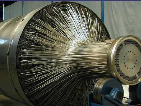
CWHE
CWHE is coils/tubes wound in spiral around a mandrel and all coils / tubes are contains within a pressure vessel. Multiple coils/tube in bundle can be flew simultaneously within the pressure vessel.

PFHE
PFHE is corrugated or serrated plate stacking on each and others to creates cross and/or counter flow paths to allow heat transfer of multiple fluids.
Although both type of HE have been widely used, CWHE and PFHE have their own special features and advantages. Below are simple comparison between both CWHE and PFHE.
| Features | Coil Wound Heat Exchanger (CWHE) | Plate-Fin Heat Exchanger (PFHE) |
| Compactness | Compact | Extremely compact |
| Heat Transfer area (m²/m³) | 20 - 300 | 300 - 1400 |
| Flow type in heat transfer | Cross-Counter | Cross and/or Counter |
| Flow pattern | Single and/or two phases | Single and/or two phases |
| Flow streams | Single or Multiple | Single or Multiple |
| Configuration | Single or multiple coil-in-vessel unit | Multiple plate-fin units |
| Flow path | 8-12mm tube | 1-2 mm flow channel |
| Risk of contaminant built-up | Less (smooth tube surface) | More (multiple channels / cores increase crevices) |
| Risk of Plugging | Lower | Higher |
| Thermal Stress Resistance | Higher (tube robustness & flexibility) | Lower (plate fin inflexible) |
| Risk of Thermal Stress | Lower | Higher |
| Gas/Liquid distribution | Less mal-distribution (single flow channel) | Higher mal-distribution (multiple unit in parallel) |
| Risk of Thermal Shock | Lower | Higher (mal-distribution lead to imbalance heat transfer) |
| Safety | Lower (tube contains within pressurized vessel - natural gas leaks to vessel) | Higher (natural gas leaks to atmosphere) |
| Availability | Higher (production continue with some tube leaks until next shutdown) | Lower (immediate production shutdown when leaks occur) |
| Transportation | Reasonable easy (with multiple bundles) | Easy (Multiple units) |
| Material | Aluminum / Stainless Steel / Carbon Steel / Others Alloy | Aluminum |
| Cost | Higher | Lower |
Related Post
- Control Around Heat Exchanger
- FAYF - Useful Heat Transfer Equation
- Few Tips on Energy Efficient & Recovery
- Heat Transfer - Internal and External Flow
- FREE E-book........A Heat Transfer Textbook
- Typical Heat Transfer Coefficient For Air-Cooled Heat
- COLLECTION of Typical Overall Heat Transfer
- COLLECTION of Fouling Factor (FF) use in Heat Exchanger Design
Labels: Brazed Plate Heat Exchanger, Compact heat Exchanger, Heat Exchanger, LNG
Wednesday, August 20, 2008
Display problem ? Click HERE

As the price of electricity, natural gas and other fossil fuels continues to climb, chemical processors are more closely examining high-temperature operations and heat-transfer systems to see if more efficiency can be had. In many cases
it can, and, as a result, heat-transfer projects are not only justifiable, but downright attractive.
There was a dialog among a few heat exchanger specialist from Alfa Laval, Paul Muller, Exergy LLC, etc. The dialog mainly discussed on strategy to improve heat transfer efficiency, heat recovery and efficient process control during this high energy price arena.
A few tips have been present :
- The energy crisis results high prices all of the time shorten paybacks. Energy efficient is one of the way to minimize cost
- Energy efficient heat transfer equipment such as Plate Heat exchanger, Gasketed Heat exchanger, Bonded Heat exchanger, etc is one of the option.
- For a service using Shell & Tube (S&T), the overall heat transfer coefficient (HTC) is around 300 Btu/h ft2°F. However, the overall heat transfer coefficient (HTC) for a compact heat exchanger can be improved 3-4 times (~1000 to 12000 Btu/h ft2°F).
- With lower overall heat transfer coefficient, this may translate into less space, smaller installation and handling cost. Capital cost may not be low as the fabrication cost for compact heat exchanger is high.
- Gasketed Heat exchanger good for maintenance. However shall take additional attention on the compatibility between gasket and fluid.
- All welded or Bonded heat exchanger may be considered if there is gasket & fluid compatible problem
- For laminar flow, heat transfer rate is only the function of fluid thermal conductivity. Operate heat transfer equipment at lamina flow during turndown could significantly reduce it heat transfer rate
- Compact heat exchanger promote turbulence. High turbulence increase heat transfer rate and reduce fouling (read more)
- Thus plant releasing hot exhaust gas from burner, boiler, gas turbine, etc to atmosphere may take the opportunity to recover heat
- Improve temperature control in process system would reduce energy usage
Not a CE subscriber... click here to subscribe FREE Chemical Engineering (CE)
Related Topic
- Practical Design Tips for Heat Exchanger Design
- COMPACT Heat Exchanger Increased Performance, Optimised area utilization, reduce CAPEX & OPEX
- Unexpected high cost of heat exchanger fouling...
- CFD in Compact Heat Exchanger
- Heat Transfer - Internal and External Flow
- Why Lower Fouling in Plate Heat Exchanger ?
Labels: Compact heat Exchanger, Heat Exchanger, Heat Recovery, Heat Transfer, Plate Heat Exchanger
Thursday, July 5, 2007

An interesting thesis related to Compact Heat Exchanger i found recently which shared by Arturo J.Pascheco-Vego
This dissertation investigates enhancement in accuracy of heat rate predictions in compact fin-tube
heat exchangers . The sources of error from a conventional approach based on correlating heat transfer coefficients, sometimes of 25 - 30%, are studied first. These include the idealized assumptions in the procedure by which correlations are found, the data compression that occurs through the correlation process, and the multiplicity of solutions for a proposed correlating function obtained using local regression
Arturo J. Pascheco-Vega, UNI of NOTRE DAME
Further reading
- CFD in Compact Heat Exchanger
- Compact heat exchanger Increased performance, optimized area utilization, reduce CAPEX & OPEX
- ALFA LAVAL - Plate technology and Designing Plate & Frame Heat Exchanger
Labels: Compact heat Exchanger, Heat Exchanger, Regression
