Sunday, April 18, 2010
Download
Thanks to David Heeley
Related Topic
- Definition of Terms Related to PRESSURE
- Oil Characterization Method in HYSYS
- An Introduction to Oil & Gas Production...
- Gas Processing, NGL Extraction & LPG Fractionation
- Typical Gas Processing Flow Scheme
Labels: Design


Thursday, November 13, 2008
- Maximum Allowable Working Pressure (MAWP)
- Design Pressure (PD)
- Maximum Allowable Operating Pressure (MAOP)
- Maximum Operating Pressure (PO,Max)
- Normal Operating Pressure (PO)
- Minimum Operating Pressure (PO,Min)
- Minimum Allowable Operating Pressure (MinAOP)
Recommended :
- Subscribe FREE - Chemical Processing
- Tips on Succession in FREE Subscription
A mechanical engineer may have different understanding than a process engineer. A process engineer from an organization may have slightly different understanding than a process engineer from another organization. A process engineer educated and/or practising engineering in a country i.e China may have different interpretation than another process engineer educated and / or practising engineering in another country i.e. USA, UK, etc. This always creates a lot of confusion, unnecessary argument and rework. In worst event could lead to hazard. Thus, first far most important thing is to define correctly the meaning of each terms so that everyone have same understanding.
Following are the simple definition of above mentioned terms. Whenever a post contains one or more of these terms, the following shall be referred.
Normal Operating Pressure (PO) - System pressure as expected to be operated at during normal operation throughout the design life of the system.
Maximum Operating Pressure (PO, Max) - Maximum system pressure as expected during normal operation, may occur in some process transient period or different operating mode or campaigns and it built into the design to cater for any uncertainties due to start-up, fouled, decayed, etc. It provides some level of flexibility for a proper operation of the system throughout the entire life of the system.
Minimum Operating Pressure (PO, Min) - Minimum system pressure as expected during normal operation, may occur in some process transient period or different operating mode or campaigns and it built into the design to cater for any uncertainties due to start-up, fouled, decayed, etc. It provides some level of flexibility for a proper operation of the system throughout the entire life of the system.
Maximum Allowable Operating Pressure (MAOP) - Maximum system pressure that can be allowed to ensure a proper operation of an a device or system.
Minimum Allowable Operating Pressure (MinAOP) - Minimum system pressure that can be allowed to ensure a proper operation of an a device or system.
Design Pressure (PD) - A pressure chosen / specified (normally chosen by process engineer) to have certain margin (i.e. 10%) above the PO,Max (or MAOP). It is a maximum pressure in the system that :
- is NOT expected during normal operation
- may only occur during emergency situation such as fire, loss of utilities, valve failure, any abnormal operation corresponding to a short duration, mal-operation, etc
Design pressure becomes MINIMUM pressure that can be hold by any components within the system without mechanical failure. It is used to define the minimum MAWP of components within the system. For example, design pressure is used to calculate minimum vessel wall thickness.
Maximum Allowable Working Pressure (MAWP) - A maximum gauge pressure permissible by a equipment / device (at coincident temperature specified for that pressure) and is governed by code i.e. ASME, JIS, GB, etc
In many cases...
MinAOP <= PO,Min <= PO <= PO,Max < MAOP < PD <= MAWP
Example :(Note : all parameters have been selected arbitrary. Just for illustration only.)
- Maximum Allowable Working Pressure (MAWP) = 12 barg
- Design Pressure (PD) = 11 barg
- Maximum Allowable Operating Pressure (MAOP) = 10 barg (~90% of 11 barg)
- Maximum Operating Pressure (PO,Max) = 8 barg
- Normal Operating Pressure (PO) = 7 barg
- Minimum Operating Pressure (PO,Min) = 6 barg
- Minimum Allowable Operating Pressure (MinAOP) = 5 barg
- Several Strategies To Minimize Relief Capacity in Back-Flow Scenario
- Only Consider Non-Recoverable Losses in PSV Inlet Line Loss Determination
- How to Resolve Issue with PSV Inlet Line Loss Exceeded 3% of Set pressure
- Concerns & Recommendations on PSV INLET line
- Few Concerns & Recommendations of PSV Discharge Tail pipe
- Relate PSV Relieving Flow to Stamped Capacity
Labels: Design, Overpressure Protection
Thursday, October 2, 2008
- Tips on Succession in FREE Subscription
- Subscribe FREE - Today Energy Solution

Gas turbine generator or gas turbine driven compressor is common used in refinery, LNG and gas plant. These turbine basically will burn gas fuel from the plant itself and hot flue gas is passed through the gas turbine. Gas turbine is then rotate and drive motor or compressor to generate power and head.
Flow and Heating Value Changes in Gas burner
Gas fuel burnt in gas burner which typically has fixed orifice nozzles. Heat output from the fixed orifice burner is proportional to flow (Q) and heating value (HV) of the gas fuel. As fuel composition change, flow and heating value will have to be changed to maintain a correct heat output. However, the magnitud of flow and heating value changes may not change linearly or there is not fix relation between flow and heating value. How to relate these two parameters ?
Gas fuel from refinery, LNG or gas plant is normally a mixtures of gas from several sources i.e. waste gas with low, medium and high heating value. A typical example is fuel gas system in LNG plant. Fuel source can be
- End Flash Gas which contains very high inerts (as high as 50%-55% Nitrogen level) and low heating value
- Flash gas from Amine regeneration unit which contains high level of CO2 and H2S, Hydrocarbon component varies from ethane to Decane including BTEX
- Demethaniser overhead which contain high Methane level
- Boil-off gas (BOD) which contains very high level of methane and low level of nitrogen
- Flash gas from Ethane, Propone, and LPG storage
- Make-up which composition varies from Methane to Decane
How to manage ?
How to manage a the flow and heating value which may vary in different magnitude and continuous variation in source heating value whilst maintaining a constant heat input into the gas turbine ? What are the parameter to be maintained or limited ?
Wobbe Index is the parameter. Mr. Wobbe found that
- Flow is proportion to gas specific gravity (SG) and;
- Heating Value is also proportion to gas specific gravity (SG)
where
Sqrt = Square root of
HHV = High Heating Value (Btu/Scf)*
SG = Specific Gravity (MWgas / 28.96)
* Some may use Lower Heating Value to define WI
Wobbe Index is used to compare the combustion energy output of different composition fuel gases. Two fuels with identical Wobbe Index at given pressure and valve setting (orifice size) the energy output will be identical. The variation in WI is typically upto 5% (but maximum could be 10% for some manufacturer).
Thus, plant fuel gas designer shall design the fuel gas system such that the fuel gas mixture feeding into the gas turbine meeting the WI limitation. In the event of any upset or interference of any fuel supply source, the control system shall be able to maintain the WI within the limitation.
Related Topic
Labels: Combustion, Design
Wednesday, September 3, 2008
- Tips on Succession in FREE Subscription
- Subscribe FREE - Today Energy Solution
What are the differences ?
In this booklet, you may find :
- Several key factors to understanding efficiency i.e. Flue gas temperature, Stack temperature, Fuel specification, Excess air, Ambient air temperature and Radiation and convection losses.
- Fuel-to-Steam Efficiency versus Flue Gas Temperature Curve
- Efficiency versus H-C ratio
- Efficiency versus O2 concentration
- Efficiency versus Ambient Temperature
- Fuel cost comparison for boiler with different efficiency
- Efficiency estimation based on Stack temperature
Related Topic
- Simple Formula To Estimate Water Viscosity
- Steam - Condensate Useful Links...
- Square-root-Square-root Formula Ease Saturated Steam-Codensate Temperature Prediction
- Steam in FIRE...
- "Fire from Ice"...
Monday, March 17, 2008

 Check valves or Non-return valves (NRV) are normally installed in piping to avoid back flow. Rotating equipment such as pump, compressor, etc will always be equipped with NRV(s) on the discharge to avoid back flow when rotating equipment is shut. Back flow creates severe surging to the rotating equipment and potentially damage the equipment. In certain process system, NRV will be employed to avoid contamination, overheating, etc due to back flow.
See the following animation how a dual disc check valve action to avoid back flow.

For details discussion on each type of check valves, please check out :
- Check valves or Non-return valves (NRV) - Wikipedia
- Check valve tutorial - Spirax Sarco
- non-slam characteristic
- pressure loss
- cost
- application
Related Post
- Why Redundant NRV in Series within a Line ?
- Why bypass Non-Return Valve (NRV) ?
- Pump Pressure Versus Head
- Why Centrifugal pump NPSH required increases with flow ?
- Tips for Centrifugal Pump
- Rule-of-thumb For Minimum Flow Recycle
- Restrcition Orifice Used in Many Applications in Different Manners
Thursday, February 28, 2008

"I understood that Maximum Allowable Working Pressure (MAWT)
- is the temperature where the vessel material will fail by its internal (design) pressure due to reduced at elevated temperature
- is subject to vessel wall thickness. MAWT should be same or higher than design temperature (DT) as fabricated wall thickness would be thicker due to material available in the market or shop or some conservative calculation roundup.
- Allowable stresses are same from-20F to 650 F (-29C to 343 C)
Is the vessel is fit from -29 C to 343 C ? Can we declare design temperature of 343 degC ?"Above analysis is pretty correct to some extent. However, it is not the complete story about the design temperature and MAWT.
MAWT for tank is subject to vessel/tank wall thickness. Above analysis has covered most (if not all) points. However, there are other devices and fitting like flange, instrument, nozzle, etc attached to the vessel and possibly, the MAWT of these devices and fittings are much lower than the MAWT of tank. We shall always refer MAWT for SYSTEM instead of a particular equipment / instrument.
Hence the design temperature of the system is come into the picture ?
As mentioned above, MAWT for equipment, instrument, piping, etc are different. Design temperature for a system is what the process demand, MAWT is what the equipment / device can take. MAWT for ALL equipment, instrument, fittings, etc within a SYSTEM shall equal or more than the design temperature as specified by process engineer.
Related Post
- Why a globe valve is located downstream of manual block valve on drain line ?
- Consider energy saving by optimizing the pump control
- Do not under estimate pump energy cost and FREE Optimization tool for better Life cycle cost
- Minimum Four Factors For Selection of Head Type on a Vessel
- Hydraulic Design Of Liquid with Pump Circuit - A revision kit...
- Hydraulic Design of Liquid Piping Systems - A revision kit...
- Is pressure drop increase with pipe schedule ?
Labels: Design
Thursday, January 17, 2008

A maintenance drain line is typically consists of a block valve (ball or gate subject to service) and a globe valve. Block valve is provided for isolation purposes while globe valve for throttling to avoid excessive flow to closed drain system.
Drain minimum line size is typically 2" (typical but may be different elsewhere). Sudden opening of 2" block valve would results excessive flow to close drain system and potentially leads to high noise level, acoustically induced vibration, erosion-corrosion, etc. A globe valve is provided on the drain line to limit sudden large flow into closed drain line.
Other than above mentioned consequences, pressure drop across globe valve will results low temperature (lower than zero degC) due to JT effect. Manual block valve located downstream of globe valve would experience similar temperature and leads to ice form at valve body, stem, shaft, etc. This would disable re-closure of the manual block valve. Thus, it is always advisable to locate manual block valve upstream of globe valve.
In earlier post (Why Restriction Orifice is some distance from Blowdown valve ?), discussed about the Blowdown valve and restriction orifice. Similarly the cold temperature may extends from globe valve to block valve which located upstream. Thus, it is always advisable to provide minimum 600 mm between block valve and globe valve.
As good operation practices, it is always advisable to minimize excessive flow through proper draining procedures. Normally the draining activities would be carried out in the following sequences :
- transfer liquid to next drum until drum to be drained is at minimum level
- depressurized pressure to about 2-3 barg
- then only drain the inventory
- to accelerate draining activity, nitrogen would be used to maintain a good positive pressure (2-3 barg) in the drum
Related Post
- Hydraulic Design Of Liquid with Pump Circuit - A revision kit...
- Hydraulic Design of Liquid Piping Systems - A revision kit...
- Why bypass Non-Return Valve (NRV) ?
- Why Restriction Orifice is some distance from Blowdown valve ?
- Workbook for Chemical Reactor Relief System Sizing
- A must have book...Emergency Relief System Design Using DIERS Technology
- Requirement of overpressure protection devices on system design to PIPING code
Thursday, January 3, 2008
There was a interesting question raised elsewhere and i find it interesting to share with my lovely reader...
Maximum recommended wall temperature (Tw) for carbon steel vessel would be about 593 C or 1100 F as quoted in API Std 521. This value is material dependent.My opinion would be :
Would it be accurate to say that the high "Design Temperature" could/should be used for Tw ?
Heat Flux Varies
Pressure containing equipment exposing to fire, the wall temperature is very much subject to type of fire, relative distance, momentum of fire, how a fire flame impinging equipment, what type of material on fire, etc and the results is heat flux would be localized.
Low Heat Transfer
Low heat transfer between wall and vapor would leads to wall temperature far higher than the gas temperature.
Environment
Environment factor such as humidity, wind condition, etc affect the heat transmission.
As above factors are difficult to quantify, thus wall temperature of equipment would be difficult to be estimated. Personally i would always recommend to put extra efforts in fire detection, prevention and evacuation of risk instead concentrating in heat flux, wall temperature for gas expansion case. Read more HERE
However, for Pressure relief device load, i would consider to reduce the set pressure as low as reasonable possible and use the conservative approach such as taking the gas temperature at relieving condition even though it is higher than the nominated design temperature, worst F factor, etc.
It is not cost effective to consider maximum recommended wall temperature (Tw) as design temperature of the system. Otherwise 90% (if not 100%) of plant design temperature would be maximum recommended wall temperature (Tw).
Related Post
- Should we consider JET FIRE for Pressure Relief Valve (PSV) load determination ?
- Should we install Butterfly valve for Pressure Relief Valve (PSV) isolation ?
- Another descrepancy found in API Std 521Jan 2007
- ERRATA - API Std 521, Pressure Relieving and Depressuring Systems
- Requirement of overpressure protection devices on system design to PIPING code
- Discussion on ISENTROPIC and ISENTHALPIC process via Relief Valve
- Use of conventional type PSV with back pressure exceeded 10% set pressure
Labels: Design, Fire, Pressure Relief Device
Wednesday, January 2, 2008
 Recent post "Do not under estimate pump energy cost and FREE Optimization tool for better Life cycle cost" has advised that pump operating cost is significant and shall assess and optimize during design, operation and maintenance.
- Eliminate unnecessary uses
- Minimize throttling
- Assess pumping system suitability for current application.
- Reduce pump speed or install appropriate speed control devices
- Consider alternative pump configurations
- Improve O&M practices
- Improve piping configuration
One of the way to reduce energy is to provide Variable Speed Drive (VSD) motor for pump. However, combination of proper control and pump configuration design may further reduce energy consumption. There were some researches have been conducted for
- Throttle control
- Standard pump control
- Optimized pump control
- save more than 45% energy comparing optimized and standard pump control
- save more than 66% energy comparing optimized and throttling control.
Related Articles
Sunday, December 30, 2007
According to US DOE, pumps are the second most widely used machines in the world, consume about 20% of the world's energy and possibly form 50% of a plant's energy cost. Many companies still take it easy and design & purchase pumping systems based on initial cost, without considering life cycle cost. Thus, Hydraulic Institute (HI) has taken an proactive initiative that educate how plants can increase efficiency and keep the energy low. It is called Pump Systems Matter (PSM). Read more HERE.
 One of the modeling tool as a product of PSM, Pump System Improvement Modeling Tool™ (PSIM), a FREE educational tool available to help you understand the hydraulic behavior of pumping systems and design / evaluate a pumping system with both cost effective and energy efficient.
PSIM capabilities include :
- System hydraulic calculations
- Centrifugal & Positive Displacement pumps
- Pump efficiency and BEP evaluation
- Variable speed pumps
- Flow & pressure control values
- Impeller trimming
- Automatic pump curve viscosity corrections
- NPSH calculations
My 2-cents of thought...
PSIM tool may be used in earlier design stage and updated from basic design to detailed design phase, last handover the model to operator for further optimization.
- The Time Has Come: Pump Systems Do Matter
- Hydraulic Design Of Liquid with Pump Circuit - A revision kit...
- Hydraulic Design of Liquid Piping Systems - A revision kit...
- Why bypass Non-Return Valve (NRV) ?
Monday, December 10, 2007
There are many head types attached to a vessel, column or drum such as hemispherical, semi-hemispherical, elliptical, flanged, etc. All these have been used in many application and however the selection of the head type is normally not documented in any process nor mechanical document and drawings. The question of application of head type has been raised many time by young engineers and the answer has been repeated many times. There is some incentive behind to list out some common reasons in application of head type.
There are few factors affecting the selection of head type :
- Allowable stress & Material used
- Access internals
- Constructibility / fabrication limitation
- Cost Saving
From stress and material saving perspective, for a vessel exposing to very high pressure hemispherical head is having highest allowable stress and minimum material. This will be followed by elliptical head and last flanged head (least allowable stress). Generally an elliptical head is in used.
Access Internals
In large vessel with the needs of accessing internals, normally an access hole (normally used manhole) will be provided.
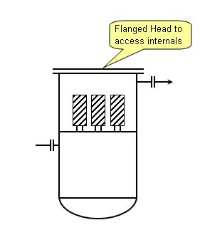
However, in small vessel with internals, a flanged head is preferred. Most of the time a swing davit will be installed on the flanged head to held the flange without assistance of any hoist.
Constructibility / fabrication limitation
Flanged head some time is used due to complexity of fabrication. There are many event where a inline condenser is mounted on top of a column.
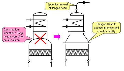
In some event where the column is small diameter (i.e. 1000mm) and a condenser with 800m ND needs to be mounted on top, there will be difficulties to use a elliptical head. those a flanged head with mating concentric reducer will be used. Apart it serve as manhole to access the internals such as demister.
Cost Saving
Sometime process and operation may required a manhole (for any specific reason) on a small vessel. Apart from construction limitation, providing a flanged head will solve the constructibility problem, it also act as manhole. Some cost saving is expected.
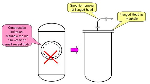
Above are some common reasons for selection of head type. I am sure there are others special reason(s) for the selection in Petrochemical & Chemical industry. If you have any example, why not sure with us ? OR if you have any photos for above applications, why not sent to me so that i can upload here ?
Related Topics
- Hydraulic Design Of Liquid with Pump Circuit - A revision kit...
- Hydraulic Design of Liquid Piping Systems - A revision kit...
- Is pressure drop increase with pipe schedule ?
Labels: Design, Material, Tower internals
Tuesday, November 20, 2007

This post is for those use ASPENTECH HYSYS 2006 release...
New bug found in ASPENTECH HYSYS Dynamic Depressuring unit, [Fisher] Valve model...
Incident
Cause
Workaround
Updated on Oct 22, 2007

Further Reading :
- Another descrepancy found in API Std 521Jan 2007
- Controlled and Non-controlled Type Depressuring.
- How to apply valve equation in HYSYS Depressuring ?
- 6 elements & factors lead to high quality question
- Carefully assess information in the web
- 12 Features required for Shutdown Valve (SDV)
Labels: Depressurization, Design, HYSYS
Wednesday, September 26, 2007
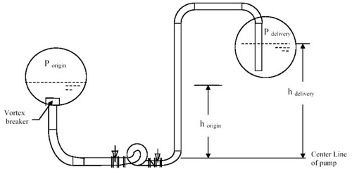
It extended to pumping liquid from one tank / drum to another tank /drum. It elaborate quite a lot on the pump head-capacity curve and interaction with piping resistance curve. the best features in this article is the STEP-by-STEP of pump hydraulic calculation, available Net Positive Suction Head (NPSHa) determination. This typical form the basis for a pump specification. A process engineer MUST read this and familiar with pump hydraulic.
Apart it also discuss the affinity law, selection guidelines for centrifugal & reciprocating pumps, pump protection methodology, etc.
Related Topics :

Labels: Design, Hydraulic, Piping
Monday, September 24, 2007

Related topics :
Labels: Design, Hydraulic, Piping
Monday, August 13, 2007

Most of us may already aware of the answer. Pressure drop will increase.
Reason being,
"The OD of the pipe is basically fixed (+ or -) but as you have already determined, the schedule number is related to the thickness, with the higher numbers indicating thicker pipe, smaller pipe ID and therefore a smaller cross sectional area of the flow path. A 2" pipe has a fairly constant OD of 2.375". The 2" schedule 40 pipe has an ID of 2.067" but a 2" schedule 160 pipe has an ID of 1.687". Obviously the schedule 160 pipe has a smaller flow path than does the schedule 40 pipe and thus for your example the velocity (and pressure drop) will be greater in the schedule 160 pipe.", by Phil LECKNER.
The post has triggered me to create some handy links...
NPS - "Nominal Pipe Size" and DN - "Diametre Nominel"
The size of pipes, fittings, flanges and valves are often given in inches as NPS - Nominal Pipe Size, or in metric units as DN - "Diametre Nominel"
Pipe Equations
Calculate cross-sectional area, weight of empty pipes, weight of pipes filled with water, inside and outside surface area
m = 10.68 (do - tw) tw
where
m = weight per foot (lbs/ft)
do = outside diameter (inches)
tw = wall thickness (inches)
Monday, July 9, 2007

BR&E - Bryan Research & Engineering Inc, has been in the oil and gas industry for years. My first contact with BR&E was 10 years ago.
Bryan Research & Engineering incepted in 1974, renowed process simulation software, ProMax having its ability to predict the performance of gas processing, refining and petrochemical processes.

ProMax capabilities includes Amine Sweetening, Glycol Dehydration, Equipment Rating/Sizing, Crude Oil Refining, LPG Recovery and Caustic Treating.
FREE articles (AMINE related) available BR&E site :
Addition of Static Mixers Increases Treating Capacity in Central Texas Gas Plant
Alternative Flow Schemes to Reduce Capital and Operating Costs of Amine Sweetening Units
Analysis of Amine Solutions by Gas Chromatography
Analysis of Various Flow Schemes for Sweetening with Amines
Converting to DEA/MDEA Mix Ups Sweetening Capacity
Decreasing Contactor Temperature Could Increase Performance
Design & Operation of a Selective Sweetening Plant Using MDEA
Design Alternatives for Sweetening LPG's and Liquid Hydrocarbons with Amines
Dome's North Caroline Plant Successful Conversion to MDEA
Improved Absorber-Stripper Technology for Gas Sweetening to Ultra-Low H2S Concentrations
Influence of Ammonia on Gas Sweetening Units Using Amine Solutions
Optimization of Amine Sweetening Units
Optimization of New and Existing Amine Gas Sweetening Plants Using Computer Simulation
Selecting Amines for Sweetening Units
Selective Absorption Using Amines
Solubility of Hydrocarbons in Physical Solvents
Sweetening LPG's with Amines
The Use of MDEA and Mixtures of Amines for Bulk CO2 Removal
Treat LPGs with Amines
Unique Acid Gas Enrichment Application
Using Mixed Amine Solutions for Gas Sweetening
The Impact Of Acid gas Loading On The Heat Of Absorption And VOC and BTEX Solubility in Amines Sweetening units
Labels: Acid Gas Removal, Amine, Design, Gas Sweethening, Process simulation, ProMax
