Sunday, February 7, 2010
In recent project, there was a topic being discussed. What are the measures can be considered to reduce the likelihood of pump cavitation ?. To answer to this question, we may need to understand some background about pump cavitation phenomenon. Previous posts as follow may probably provide some background information :
- What is pump cavitation ?
- How Pump Cavitation Sound and Looks Like ?
- Why Cavitation is Destructive ?
- Damages by Cavitation
- Relationship between NPSHa & NPSHr
Recommended :

Key to ensure no detrimental cavitation is the ensure NPSHa is higher than NPSHr. One may have to take extra note that pump cavitation can exist eventhough NPSHa is above the NPSHr of a centrifugal pump. However, it suction energy is sufficient low (below 3% head drop) and will not results cavitation which is detrimental to pump internal (discussed in "Facts About NPSH - Cavitation Even NPSHa More than NPSHr ?". Therefore, two main parameters we may have to focus are NPSHa and NPSHr.
Increase NPSHa
Previous post "How to Increase NPSHa to a Pump ?" , several points have been highlighted. Will further expand. Following equation define NPSHa :
where
Hp - pressure head
Hs - static head gain
Hf - frictional loss
Hv - velocity head
Hvp - vapor pressure head
NPSHa = Hp + Hs - Hf - Hv - Hvp
where
Hp - pressure head
Hs - static head gain
Hf - frictional loss
Hv - velocity head
Hvp - vapor pressure head
The key is to increase Hp and Hs whilst decrease Hf, Hv and Hvp
(1) Increase suction line size to reduce frictional loss (decrease Hf ) and velocity head (decrease Hv)
(2) Rearrange and /or redesign suction pipe work to minimise bends, valves and fittings to reduce frictional loss (decrease Hf )
(3) Reduce suction pipe length to reduce frictional loss (decrease Hf )
(4) Use smoother pipe (lower friction factor) to reduce frictional loss (decrease Hf ) e.g. SS instead of CS
(5) Raise suction vessel to increase static head (increase Hs )
(6) Lower pump elevation to increase static head (increase Hs)
(7) Increase pressure in suction vessel to increase suction pressure head (increase Hp) e.g. pressurize suction drum with inert gas
(8) Reduce fluid vapor pressure to decrease vapor pressure head (decrease Hvp) e.g. subcool fluid by dropping it temperature
Decrease NPSHr
Suction specific speed ( Nss) of a pump is a dimensionless number expressed as
Where
Nss : Suction Specific speed
Q : Flow rate (gpm) at the Best Efficiency Point
N : Pump rotational speed (rpm)
NPSHr : Net Positive Suction Head required (ft)
(9) Use low speed pump
Nss = ( N* Q 0.5 ) / (NPSHr)0.75
Where
Nss : Suction Specific speed
Q : Flow rate (gpm) at the Best Efficiency Point
N : Pump rotational speed (rpm)
NPSHr : Net Positive Suction Head required (ft)
(9) Use low speed pump
Decrease pump speed reduce NPSHr. Therefore use low speed pump required lower NPSHr.

(10) Use double suction impeller
Double suction impeller as shown in below image will reduce flow to each impeller by half and will reduce the NPSHr by approximately 36%-37%.

(11) Increase impeller eye area to minimize inlet pressure drop. The downside is introduction of suction recirculation. There shall be a balance in eye area selection.
(12) Use cavitation resistance material like SS (discussed in "Stainless Steel SS316 resist to CAVITATION ?"
(13) Use Suction Inducer to streamline suction flow to pump and reduce suction pressure drop
Process Treatment
Besides above measures, process engineer may also consider other process measures :
(14) Use of pump in series to reduce pump capacity of pump and reduce pump NPSHr
(15) Use of booster pump to provide sufficient head for main pump NPSHr
(16) Vortex in suction results vapor entrainment into liquid and lead to pump cavitation. Install vortex breaker at vessel outlet to avoid vapor entrainment (discussed in "Vortex Breaker to Avoid Vapor Entrainment") and;
(17) Ensure sufficient liquid height above vessel outlet to avoid vapor entrainment (discussed in "Estimate Minimum Submergence to Avoid Vapor Entrainment"
Above listed the ways to minimize likelihood of pump cavitation by increasing NPSHa, reducing NPSHr and introducing process treatment.
Related Post
Above listed the ways to minimize likelihood of pump cavitation by increasing NPSHa, reducing NPSHr and introducing process treatment.
Related Post
- Hydraulic...
- Pump
- Facts About NPSH - Cavitation Even NPSHa More than NPSHr ?
- Protect Pump for Longer Operation
- Basis & Tips on Setting Centrifugal Pump "Warming" Recycle Flow
- Flow-Delta P Protection Strategy
- Centrifugal Pump Minimum Flow Control Strategies
- Quick Check Pump Performance Using Motor Data and Field Measure Current
- Is PumpSmart Right Solution for You ?
- Vortex Breaker to Avoid Vapor Entrainment
Labels: Pump


Saturday, December 5, 2009
Display problem ? Click HERE
Recommended :
- Tips on Succession in FREE Subscription
- Subscribes to FREE Hydrocarbon Processing
 A primary factor in achieving highly reliable, effective sealing performance is to create the best fluid environment around the seal. Selection of the right piping plan and associated fluid control equipment requires a knowledge and understanding of the seal design and arrangement, fluids in which they operate, and of the rotating equipment. Providing clean, cool face lubrication, effective heat removal, personnel and environmental safety, leakage management and controlling system costs are among the specific factors that must be considered. API has established standardized piping plans for seals that provide industry guidelines for various seal arrangements, fluids and control equipment. API 682/ISO 21049 standards have default (required) connections and connection symbols for seal chamber and gland plate connections based upon the seal configuration. It is recommended that the latest edition of these standards be reviewed for up-to-date requirements, when these standards are mandated for a piece of rotating equipment.
JohnCrane, one of the most reliable manufacturer for piping plan for seal has presented a simple booklet for piping seal plan. The intent of this booklet is to illustrate the common connections that are utilized for the various piping plans, regardless of the equipment type, and therefore use generic names for connections. The end user and/or equipment manufacturer may have specific requirements that dictate what connections are to be supplied and how they are to be labeled. In the piping plans illustrated, the “Flush” connection noted for the inboard seal of a dual seal may originate from a number of suitable sources. For example, the “Flush” for piping plans 11/75 or 32/75 may be the product (Plan 11) or an external source (Plan 32).
- Tips on Succession in FREE Subscription
- Subscribes to FREE Hydrocarbon Processing
A primary factor in achieving highly reliable, effective sealing performance is to create the best fluid environment around the seal. Selection of the right piping plan and associated fluid control equipment requires a knowledge and understanding of the seal design and arrangement, fluids in which they operate, and of the rotating equipment. Providing clean, cool face lubrication, effective heat removal, personnel and environmental safety, leakage management and controlling system costs are among the specific factors that must be considered. API has established standardized piping plans for seals that provide industry guidelines for various seal arrangements, fluids and control equipment. API 682/ISO 21049 standards have default (required) connections and connection symbols for seal chamber and gland plate connections based upon the seal configuration. It is recommended that the latest edition of these standards be reviewed for up-to-date requirements, when these standards are mandated for a piece of rotating equipment.JohnCrane, one of the most reliable manufacturer for piping plan for seal has presented a simple booklet for piping seal plan. The intent of this booklet is to illustrate the common connections that are utilized for the various piping plans, regardless of the equipment type, and therefore use generic names for connections. The end user and/or equipment manufacturer may have specific requirements that dictate what connections are to be supplied and how they are to be labeled. In the piping plans illustrated, the “Flush” connection noted for the inboard seal of a dual seal may originate from a number of suitable sources. For example, the “Flush” for piping plans 11/75 or 32/75 may be the product (Plan 11) or an external source (Plan 32).
This piping seal plan booklet illustrate and describe piping seal plan features as an aid to help you determine what support system requirements will maximize the performance reliability of your fluid handling rotating equipment application.
Source : JohnCrane
Download
Source : JohnCrane
Download
Related Post
- Hydraulic...
- Visualize Spraying Nozzle Performance
- Pump Pressure Versus Head
- Why Centrifugal pump NPSH required increases with flow ?
- Tips for Centrifugal Pump
- Rule-of-thumb For Minimum Flow Recycle
- Basis & Tips on Setting Centrifugal Pump "Warming" Recycle Flow
Friday, September 18, 2009
Display problem ? Click HERE
Recommended :
- Subscribe FREE - Chemical Engineering
- Tips on Succession in FREE Subscription
 A pump with capacity of 100 m3/h and pump head of 75 m, base on suction drum elevation, fluid condition and suction piping condition, the calculated available Net Positive Suction Head (NPSHa) is 2m. This NPSHa shall be verified with NPSH required (NPSHr) by selected pump.
- Subscribe FREE - Chemical Engineering
- Tips on Succession in FREE Subscription
A pump with capacity of 100 m3/h and pump head of 75 m, base on suction drum elevation, fluid condition and suction piping condition, the calculated available Net Positive Suction Head (NPSHa) is 2m. This NPSHa shall be verified with NPSH required (NPSHr) by selected pump.How would you know if NPSHa is sufficient before the pump vendor provide the information on pump required Net Positive Suction Head (NPSHr) ?
Thoma Cavitation curve has been used to check as discussed in "Quick Check if NPSHa is Sufficient Using Thoma Cavitation Curve". Present post will discuss the usage of Suction Specific Speed for checking.
Suction specific speed ( Nss) of a pump is a dimensionless number expressed as
Suction specific speed ( Nss) of a pump is a dimensionless number expressed as
Nss = ( N* Q 0.5 ) / (NPSHr)0.75
Where
Nss : Suction Specific speed
Q : Flow rate (gpm) at the Best Efficiency Point
N : Pump rotational speed (rpm) *
NPSHr : Net Positive Suction Head required (ft)
Normal pump speed is 1450 rpm for low speed pump and 2950 rpm for high speed pump.
Soluation
Assumed pump curve is selected where pump flowrate is at best efficiency point
Pump Flow rate
Q = 100 m3/h
Q = 100 m3/h x ( 264.17 Gallon / m3 ) x (1 h / 60 min)
Q = 440.28 gpm
Pump Speed
Same as previous post, N = 2950 rpm for high speed pump
Pump Suction Specific Speed (Nss)
Same as previous post, Nss = 11000 is selected.
From above equation
Nss = ( N* Q 0.5 ) / (NPSHr)0.75
(NPSHr)0.75 = ( N* Q 0.5 ) / Nss
NPSHr = [( N* Q 0.5 ) / Nss](1/0.75)
NPSHr = [( 2950* 440.28 0.5 ) / 11000](1/0.75)
NPSHr = 10.009 ft = 3.05 m
Calculated NPSHr if 3.05 m is very close to NPSHr of 3.0 m as estimated using Thoma Curve. NPSHa of 2m is lower than NPSHr of 3.05m. Obviously the pump potential cavitate under normal operation as NPSHa less than NPSHr. Quick action to rectify the drum elevation & pump suction piping design may required to avoid potential future change.
Related Topic
Soluation
Assumed pump curve is selected where pump flowrate is at best efficiency point
Pump Flow rate
Q = 100 m3/h
Q = 100 m3/h x ( 264.17 Gallon / m3 ) x (1 h / 60 min)
Q = 440.28 gpm
Pump Speed
Same as previous post, N = 2950 rpm for high speed pump
Pump Suction Specific Speed (Nss)
Same as previous post, Nss = 11000 is selected.
From above equation
Nss = ( N* Q 0.5 ) / (NPSHr)0.75
(NPSHr)0.75 = ( N* Q 0.5 ) / Nss
NPSHr = [( N* Q 0.5 ) / Nss](1/0.75)
NPSHr = [( 2950* 440.28 0.5 ) / 11000](1/0.75)
NPSHr = 10.009 ft = 3.05 m
Calculated NPSHr if 3.05 m is very close to NPSHr of 3.0 m as estimated using Thoma Curve. NPSHa of 2m is lower than NPSHr of 3.05m. Obviously the pump potential cavitate under normal operation as NPSHa less than NPSHr. Quick action to rectify the drum elevation & pump suction piping design may required to avoid potential future change.
Related Topic
- Facts About NPSH - Cavitation Even NPSHa More than NPSHr ?
- Protect Pump for Longer Operation
- Basis & Tips on Setting Centrifugal Pump "Warming" Recycle Flow
- Flow-Delta P Protection Strategy
- Centrifugal Pump Minimum Flow Control Strategies
- Quick Check Pump Performance Using Motor Data and Field Measure Current
- Is PumpSmart Right Solution for You ?
- Vortex Breaker to Avoid Vapor Entrainment
Labels: Pump
Saturday, September 12, 2009
Display problem ? Click HERE
Recommended :
- Subscribe FREE - World Pumpv (USA & Europe only)
- Tips on Succession in FREE Subscription
 Earlier post "Relationship between NPSHa & NPSHr", Process engineer must always ensure the operating pressure along the pump (from suction to discharge) always higher than fluid vapor pressure. Net positive suction head (NPSH) is used to check if cavitation will occur. Process engineer must always ensure available Net positive suction head (NPSHa) is always higher than pump required Net positive suction head (NPSHr). In recent discussion with some engineers, there was some doubt or confusion on a simple statement. Should pump still cavitate eventhough Net Positive Suction Head available (NPSHa) higher than Net Positive Suction Head required (NPSHr) ?
Yes. Cavitation can exist eventhough NPSHa is above the NPSHr of a centrifugal pump. Based on Hydraulic institute definition of NPSHr, a NPSHr of a pump is the level of NPSHa that three percent (3%) reduction in total discharge head of the pump caused by flow blockage from cavitation vapor in the impeller eye. Pump manufacturers design their pumps based on this definition. There is still situation where head drop is below 3%. Nevertheless, it is believe this definition was based suction energy sufficient low (below 3% head drop) and will not results cavitation which is detrimental to pump internal i.e. impeller.
A few interesting facts about NPSHa and NPSHr
- Subscribe FREE - World Pumpv (USA & Europe only)
- Tips on Succession in FREE Subscription
Earlier post "Relationship between NPSHa & NPSHr", Process engineer must always ensure the operating pressure along the pump (from suction to discharge) always higher than fluid vapor pressure. Net positive suction head (NPSH) is used to check if cavitation will occur. Process engineer must always ensure available Net positive suction head (NPSHa) is always higher than pump required Net positive suction head (NPSHr). In recent discussion with some engineers, there was some doubt or confusion on a simple statement. Should pump still cavitate eventhough Net Positive Suction Head available (NPSHa) higher than Net Positive Suction Head required (NPSHr) ?Yes. Cavitation can exist eventhough NPSHa is above the NPSHr of a centrifugal pump. Based on Hydraulic institute definition of NPSHr, a NPSHr of a pump is the level of NPSHa that three percent (3%) reduction in total discharge head of the pump caused by flow blockage from cavitation vapor in the impeller eye. Pump manufacturers design their pumps based on this definition. There is still situation where head drop is below 3%. Nevertheless, it is believe this definition was based suction energy sufficient low (below 3% head drop) and will not results cavitation which is detrimental to pump internal i.e. impeller.
A few interesting facts about NPSHa and NPSHr
- Cavitation occur when NPSHa is above NPSHr, however it is not reach detrimental level
- Possible achieve 100% head when NPSHa = 1.05 to 2.5 times NPSHr
- Zero cavitation when NPSHa = 2 to 20 times HPSHr, subject to suction energy, present of air, erosive & abrasive material, etc however
- Common Zero cavitation when NPSHa = 4 times NPSHr
- NPSHa in the range of 1.1-1.3 of NPSHr for low suction energy pump design
- NPSHa in the range of 1.3-2.5 of NPSHr for high suction energy pump design
- Minimum one (1) meter NPSHa above NPSHr
Related Topic
- Protect Pump for Longer Operation
- Basis & Tips on Setting Centrifugal Pump "Warming" Recycle Flow
- Flow-Delta P Protection Strategy
- Centrifugal Pump Minimum Flow Control Strategies
- Quick Check Pump Performance Using Motor Data and Field Measure Current
- Is PumpSmart Right Solution for You ?
- Vortex Breaker to Avoid Vapor Entrainment
Sunday, April 26, 2009
Display problem ? Click HERE
Recommended :
- Subscribe FREE - World Pumpv (USA & Europe only)
- Tips on Succession in FREE Subscription
In today’s complex and frequently rugged process plant environments, liquid pumps are often over-worked and under-protected from adverse operating conditions. Many pumps run nearly non-stop 24-hours a day over multiple shifts. Poor operating conditions can reduce pump performance, require extra maintenance, shorten their lives and increase costs.
- Subscribe FREE - World Pumpv (USA & Europe only)
- Tips on Succession in FREE Subscription
In today’s complex and frequently rugged process plant environments, liquid pumps are often over-worked and under-protected from adverse operating conditions. Many pumps run nearly non-stop 24-hours a day over multiple shifts. Poor operating conditions can reduce pump performance, require extra maintenance, shorten their lives and increase costs.Unexpectedly losing a pump is often an expensive or even a dangerous problem in a chemical plant. The results of a pump failure potentially range from the loss of product in sensitive pharmaceutical batch control applications to damage to other nearby equipment from pressure build-up of material that isn’t moving or even to safety hazards when a pump fails to shut-down and literally burns-up in the presence of combustible materials. It really pays to protect and care properly for your pumps. Read more here
DownloadRelated Post
- Basis & Tips on Setting Centrifugal Pump "Warming" Recycle Flow
- Removal of Specific Heat ratio (k) in the Mach No. & Critical Pressure Calculation
- Two Useful Equations For Flow Conversion between Air - Vapor & Actual - Standard
- Potential Problem associate with Double NRV in Series within a Line
- Restrcition Orifice Used in Many Applications in Different Manners
- A refresh to Process Engineer on few phenomenons in restriction orifice
- Why Restriction Orifice is some distance from Blowdown valve ?
Labels: Pump
Wednesday, October 1, 2008
Display problem ? Click HERE
Earlier post "Why bypass Non-Return Valve (NRV) ?" discussed the purpose of providing manual block valve across Non-Return Valve (NRV) on centrifugal pump discharge. Typical the purpose covers :
- Pump priming
- Pump warming
- NRV downstream section draining
Recommended :
Subscribe FREE - Chemical Processing

Now the question is focus on pump warming. What is the basis of setting this recycle flow rate ? Lets first define the purpose, how it is implemented and how to set the flow.
Purpose
The main purpose of the bypass line is to maintain a minimum temperature different between the pump (and associate piping ) and the pump suction fluid temperature to avoid temperature shock in the event of standby pump is started-up automatically.
How it is implemented ?
The bypass can be
- fixed restriction orifice (RO) or;
- non-return valve (NRV) with hole or;
- globe valve
The bypass flow rate should be sufficient to cater for :
i) Start-up : pump and associate piping heat-up from minimum ambient to normal suction temperature within a reasonable time i.e. 2 hours
ii) Normal operation : heat leakage via insulation during normal operation
Tips
Generally above calculation are time consuming. Experience based approach may be taken where setting the RO / NRV hole size as 6-8 mm or install a one (1) in globe valve.
Related Post
Related Post
- Removal of Specific Heat ratio (k) in the Mach No. & Critical Pressure Calculation
- Two Useful Equations For Flow Conversion between Air - Vapor & Actual - Standard
- Potential Problem associate with Double NRV in Series within a Line
- Restrcition Orifice Used in Many Applications in Different Manners
- A refresh to Process Engineer on few phenomenons in restriction orifice
- Why Restriction Orifice is some distance from Blowdown valve ?
Labels: Fluid Flow, Hydraulic, NRV, Pump
Monday, September 1, 2008
Display problem ? Click HERE
Recommended :
- Subscribe FREE - World Pumpv (USA & Europe only)
- Tips on Succession in FREE Subscription
Centrifugal compressor potentially surge when the flow crosses the surge point and potentially leads to catastrophic failure. Anti-surge control is implemented to safeguard a centrifugal compressor. Flow-Delta anti-surge protection strategy (below figure) is one of the anti-surge control widely applied in centrifugal compressor as anti-surge protection strategy.

Recommended :
Subscribe FREE - Processing Magazine
 Similarly, centrifugal pump may subject to cavitation when the flow reach it minimum allowable flow where possibly severe internal recirculation occurred and potentially damage the pump impeller. View damages caused by pump cavitation. If you have not heard before how a cavitation likes, check out "How Pump Cavitation Sound and Looks Like ?". A process engineer shall always implements minimum flow protection strategy for centrifugal pump to avoid the potential damage due to cavitation. Typical centrifugal Pump Minimum Flow Control Strategies are:
(i) A restriction orifice on pump discharge recycle line
(ii) A flow meter on pump discharge with control valve on recycle line
(iii) Use Automatic Recirculation Valves (ARC) valve
(iv) Flow-Delta P Control
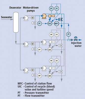
Yes. Above strategy is feasible. Figure above shows application of Flow-Delta anti-surge protection strategy for centrifugal pump minimum flow protection in Offshore Seawater injection system.
A paper written by S. Mirsky (from CCC) described in brief the implementation of the above strategy. Download...
- Subscribe FREE - World Pumpv (USA & Europe only)
- Tips on Succession in FREE Subscription
Centrifugal compressor potentially surge when the flow crosses the surge point and potentially leads to catastrophic failure. Anti-surge control is implemented to safeguard a centrifugal compressor. Flow-Delta anti-surge protection strategy (below figure) is one of the anti-surge control widely applied in centrifugal compressor as anti-surge protection strategy.
Typical Flow-Delta anti-surge protection strategy
Recommended :
Subscribe FREE - Processing Magazine
Similarly, centrifugal pump may subject to cavitation when the flow reach it minimum allowable flow where possibly severe internal recirculation occurred and potentially damage the pump impeller. View damages caused by pump cavitation. If you have not heard before how a cavitation likes, check out "How Pump Cavitation Sound and Looks Like ?". A process engineer shall always implements minimum flow protection strategy for centrifugal pump to avoid the potential damage due to cavitation. Typical centrifugal Pump Minimum Flow Control Strategies are:(i) A restriction orifice on pump discharge recycle line
(ii) A flow meter on pump discharge with control valve on recycle line
(iii) Use Automatic Recirculation Valves (ARC) valve
(iv) Flow-Delta P Control
Is it feasible applying Flow-Delta P protection strategy in pump minimum flow protection?
Yes. Above strategy is feasible. Figure above shows application of Flow-Delta anti-surge protection strategy for centrifugal pump minimum flow protection in Offshore Seawater injection system.
A paper written by S. Mirsky (from CCC) described in brief the implementation of the above strategy. Download...
Labels: Minimum flow, Pump
Thursday, August 21, 2008
Display problem ? Click HERE
Recommended :
- Subscribe FREE - World Pumpv (USA & Europe only)
- Tips on Succession in FREE Subscription
The discussion on pump cavitation have been circulated around what is pump cavitation ? how destructive a cavitation ? how cavitation sound & looks like ? what the relationship between NPSHa & NPSHr ? how to increases NPSHa to minimize / avoid cavitation ?... We understood that a minimum flow shall be maintained to minimize cavitation, avoid impeller damage and extend pump lifespan. "Rule-of-thumb For Minimum Flow Recycle" discussed few factors possibly determining the minimum flow recirculated around centrifugal pump.
- Subscribe FREE - World Pumpv (USA & Europe only)
- Tips on Succession in FREE Subscription
The discussion on pump cavitation have been circulated around what is pump cavitation ? how destructive a cavitation ? how cavitation sound & looks like ? what the relationship between NPSHa & NPSHr ? how to increases NPSHa to minimize / avoid cavitation ?... We understood that a minimum flow shall be maintained to minimize cavitation, avoid impeller damage and extend pump lifespan. "Rule-of-thumb For Minimum Flow Recycle" discussed few factors possibly determining the minimum flow recirculated around centrifugal pump.
What are the Centrifugal Pump Minimum Flow Control Strategies can be considered ?
There are number ways to implement minimum flow protection strategy for centrifugal pump. Typically they are:
(i) A restriction orifice on pump discharge recycle line
(ii) A flow meter on pump discharge with control valve on recycle line
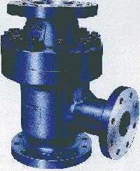
(iii) Use Automatic Recirculation Valves (ARC) valve
(iv) Flow-Delta P and flow meter on pump discharge with control valve on recycle line
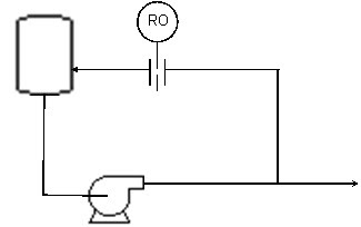
Fig. 1 restriction orifice on pump discharge recycle line
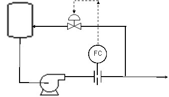
Fig. 2 Flow meter on pump discharge with control valve on recycle line
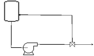
Fig. 3 Automatic Recirculation Valves (ARC) valve
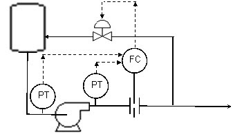
Fig. 4 Flow-Delta P and flow meter on pump discharge with control valve on recycle

The following list out the advantages and disadvantages for above four options
Restriction orifices
- Simple installation
- Maintenance free
- Large pump
- Waste energy all time
- Limit maximum pump output.
Orifice plate in the discharge line
- No continuous recycle thus energy saving
- consumes energy and also slightly reduces pump capacity.
- Using orifice plate to measure flow will results high inaccuracy e.g. minimum flow is 40% of maximum flow, 7% of the set point may be expected.
ARC valve
- Simple & effective
- Lack of flexibility.
- Unstable operation
- expensive
Sketches below show outlook and operation of an ARC valve
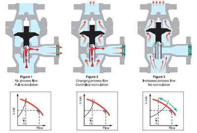
- Similar to orifice plate option
- Good option for load sharing of pumps in parallel installation
Restriction orifice option is the most common option adopted in many applications with LOW capacity system and a process engineer is advisable to consider this option. However, for HIGH system and appreciable energy losses is possible, a process engineer is advised to consider flow orifice with control valve option. ARC valve may be a good option to consider if process engineer is well aware of the fluid characteristics and familiar with the operation & dynamic of ARC valve. For very high capacity system and load sharing may be expected, process engineer may consider Flow-Delta P option.
Related Topic
- Quick Check Pump Performance Using Motor Data and Field Measure Current
- Is PumpSmart Right Solution for You ?
- Special Flowmeter & Piping Release...
- Vortex Breaker to Avoid Vapor Entrainment
- Estimate Minimum Submergence to Avoid Vapor Entrainment
- Estimate Pump Power Consumption without Vendor Information
- Trim Centrifugal Pump Impeller for Reduced Head
- Quick Check if Pump Performance Curve (Water) is Good for High Viscosity Fluid
Labels: Minimum flow, Pump
Monday, August 4, 2008
Display problem ? Click HERE
Recommended :
- Subscribe FREE - World Pumpv (USA & Europe only)
- Tips on Succession in FREE Subscription
There is a centrifugal pump working on the field and a flow meter is continuously measuring the flow rate delivered by the centrifugal pump. You noticed that flow meter indicating flow rate same as normal recorded flow rate, however, the downstream system indicating that there is reduction in flow. Flow meter Calibration is one of the normal way to confirm if the flow meter is working correctly. Prior to this, you may consider the following approach to quickly check if the pump delivering good flow and cross check with the flow meter.
This approach basically use the field tested pump curve as follow.

Field tested pump curve
Pump power consumed by pump shaft,
Es = (dH x Q x SG) / (3960 x Pump Eff. x Kv) [Eq. 1]
where,
Es = Pump shaft power (HP) consumed
dH = Pump head (ft)
SG = fluid specific gravity
Pump Eff. = Pump efficiency
Kv = Viscosity Correction Factor
Power deliver by a motor to pump shaft,
Em = (1.732 x V x I x Motor Eff. x P.F.) / (746) [Eq. 2]
where,
Em = Power deliver by motor to pump shaft
V = Voltage (v)
I = Current (amp)
Motor eff. = Motor efficiency
P.F. = Motor Power Factor
Recommended :
- Subscribe FREE - Power Engineering (USA, Canada & Mexico)
- Subcribe FREE - Power Engineering (International)
 Case study
A centrifugal pump transferring water from tank to a drum. A pressure transmitter located on the pump discharge. This estimated pump head based on differential pressure is 2000 ft. Fluid SG is 0.9932. From field, Voltage and current for the centrifugal pump are 460 volts and 323.1 amp. The flow meter is indicating flow rate of 385 gpm. Check if the flow meter is correctly measuring the flow rate.
From motor catalog, you may obtain motor efficiency (motor Eff.) and power factor (P.F.). For example, a motor with Motor Eff = 95% and P.F.=90%. The motor efficiency and P.F. may varies a bit (2%-5%). But they can be assumed same.
Power consumed / delivered,
From [Eq. 2],
==> Em = (1.732 x V x I x Motor Eff. x P.F.) / (746)
==> Em = (1.732 x 460 x 323.1 x 0.95 x 0.9) / (746)
==> Em = 295 HP
From above pump curve,
With Em = 295 HP
==> Flow, Q = 400 gpm, Pump Eff. 68% and Pump Head = 2000 ft.
Q = 400 gpm > 385 gpm as measured by flow meter. This indicates that the flow meter may not perform correctly.
Cross check with [Eq. 1],
As fluid is water,
==> Kv = 1.
For other type of fluid, may check out the viscosity correction factor using curve (by HI) presented in "Quick Check if Pump Performance Curve (Water) is Good for High Viscosity Fluid".
From [Eq. 1],
==> Es = (dH x Q x SG) / (3960 x Pump Eff. x Kv)
==> Q= Es x (3960 x Pump Eff. x Kv) / (dH x SG)
==> Q= 295 x (3960 x 0.68 x 1) / (2000 x 0.9932)
==> Q = 400 gpm
It is useful to generate a Current versus Flow curve as follow :
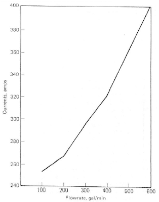
With this curve, operator may use it quickly check against the flow meter.
- Subscribe FREE - World Pumpv (USA & Europe only)
- Tips on Succession in FREE Subscription
There is a centrifugal pump working on the field and a flow meter is continuously measuring the flow rate delivered by the centrifugal pump. You noticed that flow meter indicating flow rate same as normal recorded flow rate, however, the downstream system indicating that there is reduction in flow. Flow meter Calibration is one of the normal way to confirm if the flow meter is working correctly. Prior to this, you may consider the following approach to quickly check if the pump delivering good flow and cross check with the flow meter.This approach basically use the field tested pump curve as follow.
Field tested pump curve
Pump power consumed by pump shaft,
Es = (dH x Q x SG) / (3960 x Pump Eff. x Kv) [Eq. 1]
where,
Es = Pump shaft power (HP) consumed
dH = Pump head (ft)
SG = fluid specific gravity
Pump Eff. = Pump efficiency
Kv = Viscosity Correction Factor
Power deliver by a motor to pump shaft,
Em = (1.732 x V x I x Motor Eff. x P.F.) / (746) [Eq. 2]
where,
Em = Power deliver by motor to pump shaft
V = Voltage (v)
I = Current (amp)
Motor eff. = Motor efficiency
P.F. = Motor Power Factor
Recommended :
- Subscribe FREE - Power Engineering (USA, Canada & Mexico)
- Subcribe FREE - Power Engineering (International)
Case studyA centrifugal pump transferring water from tank to a drum. A pressure transmitter located on the pump discharge. This estimated pump head based on differential pressure is 2000 ft. Fluid SG is 0.9932. From field, Voltage and current for the centrifugal pump are 460 volts and 323.1 amp. The flow meter is indicating flow rate of 385 gpm. Check if the flow meter is correctly measuring the flow rate.
From motor catalog, you may obtain motor efficiency (motor Eff.) and power factor (P.F.). For example, a motor with Motor Eff = 95% and P.F.=90%. The motor efficiency and P.F. may varies a bit (2%-5%). But they can be assumed same.
Power consumed / delivered,
From [Eq. 2],
==> Em = (1.732 x V x I x Motor Eff. x P.F.) / (746)
==> Em = (1.732 x 460 x 323.1 x 0.95 x 0.9) / (746)
==> Em = 295 HP
From above pump curve,
With Em = 295 HP
==> Flow, Q = 400 gpm, Pump Eff. 68% and Pump Head = 2000 ft.
Q = 400 gpm > 385 gpm as measured by flow meter. This indicates that the flow meter may not perform correctly.
Cross check with [Eq. 1],
As fluid is water,
==> Kv = 1.
For other type of fluid, may check out the viscosity correction factor using curve (by HI) presented in "Quick Check if Pump Performance Curve (Water) is Good for High Viscosity Fluid".
From [Eq. 1],
==> Es = (dH x Q x SG) / (3960 x Pump Eff. x Kv)
==> Q= Es x (3960 x Pump Eff. x Kv) / (dH x SG)
==> Q= 295 x (3960 x 0.68 x 1) / (2000 x 0.9932)
==> Q = 400 gpm
It is useful to generate a Current versus Flow curve as follow :
Current versus Flow curve
With this curve, operator may use it quickly check against the flow meter.
Related Topic
- Is PumpSmart Right Solution for You ?
- Special Flowmeter & Piping Release...
- Vortex Breaker to Avoid Vapor Entrainment
- Estimate Minimum Submergence to Avoid Vapor Entrainment
- Estimate Pump Power Consumption without Vendor Information
- Trim Centrifugal Pump Impeller for Reduced Head
- Quick Check if Pump Performance Curve (Water) is Good for High Viscosity Fluid
Saturday, July 26, 2008
Display problem ? Click HERE
Recommended :
Subscribe FREE - World Pump
PumpSmart is an intelligent system includes the advanced pump Control, Protection, and Optimization logic designed to prevent failures, improve pump reliability and maximize the Flow Economy of process systems. It is one of the great product by ITT PumpSmart Control Solutions. PumpSmart utilizing smart VFD controller and ITT proprietary control software to provide advanced process control, enhanced reliability through failure prevention, reduced life cycle costs and lower energy costs - up to 65%.
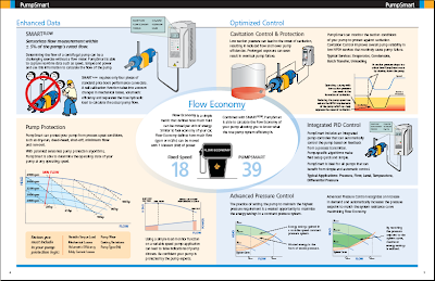
PumpSmart can :
Visit PumpSmart
PumpSmart presentation (Video Clip)
(Click here to view using Web Browser)
Subscribe FREE - World Pump
PumpSmart is an intelligent system includes the advanced pump Control, Protection, and Optimization logic designed to prevent failures, improve pump reliability and maximize the Flow Economy of process systems. It is one of the great product by ITT PumpSmart Control Solutions. PumpSmart utilizing smart VFD controller and ITT proprietary control software to provide advanced process control, enhanced reliability through failure prevention, reduced life cycle costs and lower energy costs - up to 65%.
PumpSmart can :
- works with any pump.
- capture real-time data such as speed, torque and power to calculate the flow of the pump.
- protect pump from process upset conditions such as dry-run, dead-head, shut-off, minimum flow and run-out.
- monitor pump suction conditions to protect against cavitation and improves overall pump reliability
- control the pump based on feedback from a process transmitter.
- calculate the Flow Economy of pump and true pump system efficiency.
Visit PumpSmart
PumpSmart presentation (Video Clip)
(Click here to view using Web Browser)
Related Topic
- Vortex Breaker to Avoid Vapor Entrainment
- Estimate Minimum Submergence to Avoid Vapor Entrainment
- Estimate Pump Power Consumption without Vendor Information
- Trim Centrifugal Pump Impeller for Reduced Head
- Quick Check if Pump Performance Curve (Water) is Good for High Viscosity Fluid
- Quick Check if NPSHa is Sufficient Using Thoma Cavitation Curve
- Quick Pump Selection...
Labels: Pump
Tuesday, July 22, 2008
Display problem ? Click HERE
Recommended :
Subscribe FREE - Processing Magazine
A free surface vortex can form when a liquid exit via a nozzle or hole below it liquid surface (bottom or side). Minimum submergence height (S), can be calculated according to earlier post"Estimate Minimum Submergence to Avoid Vapor Entrainment" shall be maintained in order to avoid gas entrainment in the the liquid outlet. In case of gas entrainment into pump, it will reduce pump capacity and potentially affect the plant performance.In some cases, the estimated minimum submergence height (S) could be high and it may not be cost effective and providing vortex breaker is another option to tackle gas entrainment issue. A vortex breaker is a simple plate(s) arrangement which intentionally to break the vortex vertically or horizontally. Following images are some plate arrangement which may be used as vortex breaker.

The first three are basically a horizontal plate to segregate vortex from inlet while last (bottom) is vertical plates (4 or 6 plates) to break circulation of liquid. Following images are some typical applications of vortex breaker.

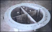
Related Topic
- Estimate Minimum Submergence to Avoid Vapor Entrainment
- Estimate Pump Power Consumption without Vendor Information
- Trim Centrifugal Pump Impeller for Reduced Head
- Quick Check if Pump Performance Curve (Water) is Good for High Viscosity Fluid
- Quick Check if NPSHa is Sufficient Using Thoma Cavitation Curve
- Quick Pump Selection...
Labels: Pump
Monday, July 21, 2008
Display problem ? Click HERE
Recommended :
Subscribe FREE - Processing Magazine
A free surface vortex potentially form when :i) liquid exit via a nozzle or hole below it liquid surface (bottom or side) and
ii) liquid height (between liquid surface and nozzle/hole) is below a minimum submergence height (S).
When free surface vortex is formed, gas entrainment will occur and pull vapor / gas above liquid surface exit together with liquid via the nozzle / hole. The following image shows series of events taken place when a free surface vortex is formed.
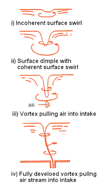
Similarly, gas entrainment occurs at pump suction intake point causes vapor/gas enter pump reduce pumping capacity and vibration (due to pump impeller imbalance).
Submergence (S) is defined as the height between liquid surface and the exit hole. Following images show submergence (S) for different intake location and nozzle type.

Submergence subjects to intake velocity with the following relationship :
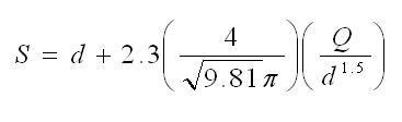
where
d = intake diameter (m)
Q = intake flowrate (m3/s)
Example :
A pump transferring liquid from a suction tank to a reactor at a rate of 227.1m3/h. The pump suction inlet nozzle with a internal diameter of 304.9mm is located horizontally. What is the minimum submergence to avoid gas entrainment ?
d = intake diamter = 304.9 /1000 = 0.3049 m
Q = intake flowrate = 227.1 / 3600 m3/h = 0.063 m3/s
S = 0.3049 + 2.3 (4 / SQRT(9.81) x PI) (0.063 / 0.3049)
S = 0.66 m
Thus, minimum submergence (S) is 0.66 m above intake nozzle.
* SQRT = Square-root
** PI = 3.141592654
Related Topic
- Estimate Pump Power Consumption without Vendor Information
- Trim Centrifugal Pump Impeller for Reduced Head
- Quick Check if Pump Performance Curve (Water) is Good for High Viscosity Fluid
- Quick Check if NPSHa is Sufficient Using Thoma Cavitation Curve
- Quick Pump Selection...
- Estimate Pump Efficiency base on Specific Speed (Ns)
- Pump Efficiency Estimation Without Vendor Information
Labels: Pump
Saturday, July 5, 2008
Display problem ? Click HERE
A question raised by a young engineer in this blog...
Earlier discussion in "Pump Efficiency Estimation Without Vendor Information", shaft power of pump can be estimated using the following equation :
Earlier discussion in "Pump Efficiency Estimation Without Vendor Information", shaft power of pump can be estimated using the following equation :
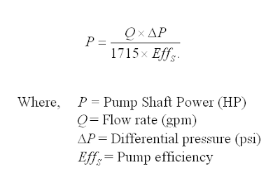 For high flow, the efficiency can be estimated according to equation to "Estimate Pump Efficiency base on Specific Speed (Ns)".
How to estimate power consumption for pump during normal operation without motor vendor information ?
To estimate power consumption of a motor, first thing is to estimate the pump shaft power (Ps) as shown above. The power consumption of motor (Pm) can be related with pump shaft power (Ps) with motor efficiency (Eff,m). One special characteristic is motor efficiency is higher the motor rating, higher the efficiency.
Pm = Ps / Eff,m
Where
Pm = Power consumption of motor,
Ps = Pump shaft power
Eff,m = Motor efficiency (see following table)
The following table tabulate the motor rating and associates motor efficiency, assuming at best efficiency point (BEP).
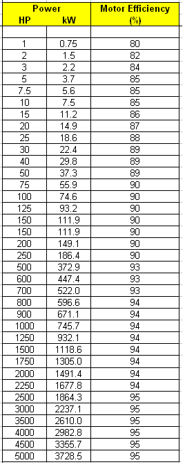
Source : Pocket Guide to Chemical Engineer
For example,
A pump with capacity of 440 gpm, pump head of 264.1 ft and pump speed of 2950 rpm, calculate the power consumption of motor.
Step 1 : Estimate pump shaft efficiency
Calculate Specific speed (Ns). Refer to Estimate Pump Efficiency base on Specific Speed (Ns).
Ns = 996. Pump shaft efficiency, Eff,s = 74%.
Step 2 : From above equation, Pump shaft power, Ps = 37.7 HP (~ 28.1 kW).
Step 3 : From above table, Pre-select motor and its motor efficiency. Motor rating = 40 HP with motor efficiency, Eff,m = 89%, delivered power = 40 x 89% = 35.6 HP, less than Pump Shaft Power (Ps) of 37.7 HP. The motor is not acceptable.
Next size motor, Motor rating = 50 HP with motor efficiency (Eff,m) = 89%, delivered power = 50 x 89% = 44.5 HP, more than Pump Shaft Power (Ps) of 37.7 HP. The motor is acceptable.
Step 4 : From above equation, power consumption, Pm = 37.7 / 89% = 42.4 HP
Step 4 : From above equation, power consumption, Pm = 37.7 / 89% = 42.4 HP
Related Topic
- Trim Centrifugal Pump Impeller for Reduced Head
- Quick Check if Pump Performance Curve (Water) is Good for High Viscosity Fluid
- Quick Check if NPSHa is Sufficient Using Thoma Cavitation Curve
- Quick Pump Selection...
- Estimate Pump Efficiency base on Specific Speed (Ns)
- Pump Efficiency Estimation Without Vendor Information
Labels: Pump
Saturday, June 21, 2008
Display problem ? Click HERE
 Few years back involved in a commissioning of a gas processing plant. The process engineer hasover-estimated the pressure drop on the Deminineralized Water (DW) pump discharge line (actual pressure drop on site is much lower). Extra pressure drop will be throttled by the manual and/or automatic control valve. This implied that the DW pump works "extra" as well as the valve.
There are a few impacts associate with this simple over-estimate :
- Increased pump power consumption
- Extra pressure drop across control valve increases wear and tear and reduce valve lifespan.
- Operates at higher pressure level increases safety risk
As the projects is promoting Green philosophy and ALARP principles, the management has decided to minimize the consequence and/or optimize above situation. There are few straight forward to above situation :
- Change fixed speed to variable speed
- Trim impeller
Change speed of motor is considered one the very good option as the system will reduce pump head to suit system curve demand, reduce power consumption and operates at lower pressure (reduce safety risk). In additional, in the event the pressure drop on the system increases in future due to fouling, corroded pipe, etc, the pump speed can be increases anytime to meet the new demand. Nevertheless, this involved inclusion of extra device like frequency inverter and cabling, potential motor size change, extra installation & testing time and delay in start-up, this option has been "parked" for future consideration.
Trim pump impeller is another way to tackle above issue. Although it is not the best option, it is considered a reasonable and acceptable option during this commissioning and start-up period. Now, the question is
how much should i trim the impeller in order to meet new condition ?
The Affinity Law is concept that you should looks for. The Affinity Law is one of common concept in pump industry and used widely in estimating pump new performance in the event of impeller size changed, motor speed changed and both of above. Umbrella
The Affinity Law states that for similar conditions of flow (i.e. substantially same efficiency) the capacity (Q) will vary directly with the ratio of speed (N2/N1) and/or impeller diameter (D2/D1) and the head with the square of this ratio at the point of best efficiency (BEP). Other points to the left or right of the best efficiency point will correspond similarly. Refer table to view the relation between capacity (Q), speed (N), impeller size (D), pump head (H) and motor power (bhp).
 Figure 1 : Affinity Law Relationship
Source : Centrifugal Pump : Design & Application
(Click to view larger chart)
Above law is a fundamental relationship which derived from theory. There is some deviation of performance in real world. The higher the percentage of impeller being trimmed, the the higher the deviation is. Thus, a correction factor (Kc) shall be included in order to correct the performance. Following Impeller Trim Correction may be used to correct the the performance.
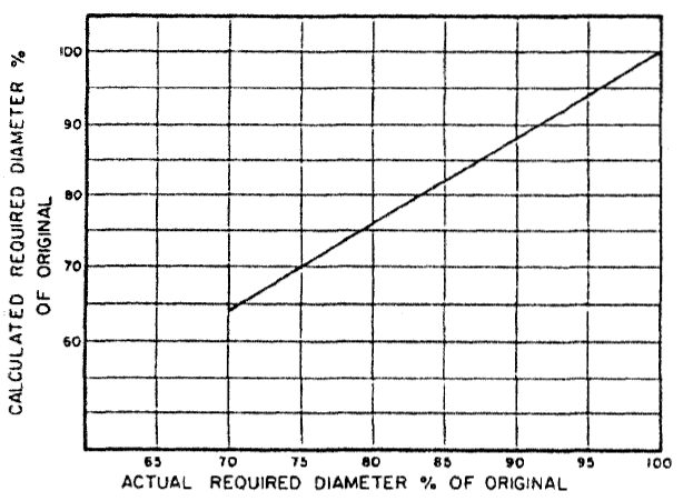 Figure 2 : Impeller Trim Correction
Source : Centrifugal Pump : Design & Application
(Click to view larger chart)
The are two conditions associate to trimming of impeller.
- Specific speed, Ns less than 2500, Impeller trim to be limited to 70%. Trim cut below 70% may cause significant efficiency drop and instable operation.
- Specific speed, NS = 2500-4000, Impeller trim to be limited to 90%. Trim cut
below 90% may cause possible hydraulic problems associated with inadequate vane overlap.
Example,
An existing pump impeller size is 7-in with pump head of 135 ft. What is the impeller trim is required to reduce pump head to 90 ft ?
H2/H1 = (D2/D1)^2
(D2/D1) = (H2/H1)^0.5
(D2/D1) = (90/135)^0.5
(D2/D1) = 0.8163 (81.63%)
From figure 2 : Impeller Trim Correction chart,
Corrected (D2/D1) = 84% (more than 70%, OK for Ns less than 2500)
Thus, D2 = 0.84 x 7 = 5.88 inches.
The associate new Flow (Q) and Power (bhp) can be calculated according to above equation with the D2/D1. The new efficiency can be recalculated base on the Specific Speed (Ns) as discussed in "Estimate Pump Efficiency base on Specific Speed (Ns)".
An existing pump impeller size is 7-in with pump head of 135 ft. What is the impeller trim is required to reduce pump head to 90 ft ?
H2/H1 = (D2/D1)^2
(D2/D1) = (H2/H1)^0.5
(D2/D1) = (90/135)^0.5
(D2/D1) = 0.8163 (81.63%)
From figure 2 : Impeller Trim Correction chart,
Corrected (D2/D1) = 84% (more than 70%, OK for Ns less than 2500)
Thus, D2 = 0.84 x 7 = 5.88 inches.
The associate new Flow (Q) and Power (bhp) can be calculated according to above equation with the D2/D1. The new efficiency can be recalculated base on the Specific Speed (Ns) as discussed in "Estimate Pump Efficiency base on Specific Speed (Ns)".
Above demonstrates the new sets Flow, Power, Head and efficiency for a Trimmed impeller for a single point. If you have the existing pump curve (H vs Q), you may re-establish the new curve (H2 vs Q2) base on existing curve (H1 vs Q1) for a trimmed impeller size (D2). With new curve, you may read the H2 at required pump flow i.e. Qr. If the H2 @ Qr is lower than required pump head (Hr), it signified the impeller is over-trimmed and D2 shall be increased (reduced trim percentage), vice versa until you get the curve with same pump flow (Q1=Q2=Qr) with reduced pump head (H2=Hr).
Related Topic
Related Topic
Labels: Pump
Tuesday, June 17, 2008
Display problem ? Click HERE
A crude transfer pump with capacity of 500 gpm and pump head of 400 ft pumping crude with viscosity of 88 centistokes. With these basic information, Process engineer will prepare a pump specification. Together with other mechanical requirements, all these documents will be submitted to pump vendor for pump quotation. After proper pump selection, pump vendor will submit the quotation with pump curve. The curve indicating performance curve for water instead of crude. The marked operating point on the curve (water) are capacity of 505 gpm, pump head of 417 ft and pump efficiency of 75%. Is the selected pump acceptable ?
Obviously the pump performance curve for water can not be make equivalent to performance when pumping crude with viscosity of 88 centistokes. With following correction charts, the capacity, head and efficiency when pumping crude with identical pump can be found.
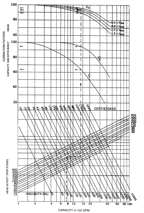 Chart 1 : Correction chart for flow in the range of 100 gpm - 10000 gpm
(Click to view larger chart)
 Chart 1 : Correction chart for flow in the range of 10 gpm - 100 gpm
(Click to view larger chart)
- Capacity correction = 0.99
- Head correction = 0.96
- Efficiency correction = 0.8
The corrected pump capacity when pumping crude @ 88 cSt = 0.99 x 510 gpm = 500 gpm.
The corrected pump head when pumping crude @ 88 cSt = 0.96 x 417 ft = 400 ft.
Above indicated the selected pump is acceptable.
When calculating the pump shaft power, the pump efficiency shall be corrected by multiplying the efficiency obtain from pump curve (water) with efficiency correction.
Related Topic
Labels: Pump
Monday, June 16, 2008
Display problem ? Click HERE
A pump with capacity of 100 m3/h and pump head of 75 m, base on suction drum elevation, fluid condition and suction piping condition, the calculated available Net Positive Suction Head (NPSHa) is 2m. This NPSHa shall be verified with NPSH required (NPSHr) by selected pump.How would you know if NPSHa is sufficient before the pump vendor provide the information on pump required Net Positive Suction Head (NPSHr) ?
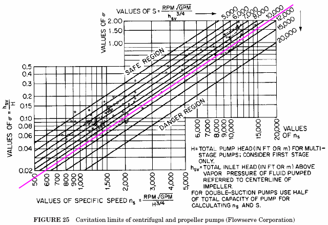
Horizontal axis : Specific speed (Ns)
Vertical axis : Thoma Sigma number, Sigma = NPSHr / H, where H=pump head
Incline line : Suction specific speed (Nss)
All points above the pink line are indicates pump operate in safe region.
From above example, the calculated pump specific speed (Ns) is about 996. From Thoma cavitation curve, with Ns=996 vertically upward cross the pink limiting line, read horizontal to the left, the Thoma sigma number is about 0.04.
Pump required Net Positive Suction Head (NPSHr) is 0.04 x 75 = 3m (more than NPSHa of 2m). This indicated that the pump potential cavitate under normal operation as NPSHa less than NPSHr. Quick action to rectify the drum elevation & pump suction piping design may required to avoid potential future change.
Above pink limiting line was based on suction specific speed, Nss = 11000. In many event, pump manufacturer may design pump with normal Nss of 8000-8500.
Related Topic
- Quick Pump Selection...
- Estimate Pump Efficiency base on Specific Speed (Ns)
- Pump Efficiency Estimation Without Vendor Information
- How to Detect Pump Cativation ?
- How to Increase NPSHa to a Pump ?
- Relationship between NPSHa & NPSHr
- Why Centrifugal pump NPSH required increases with flow ?
Labels: Pump
