Thursday, January 7, 2010
Recommended :
- Subscribe FREE - Chemical Engineering
- Tips on Succession in FREE Subscription
 Earlier post "Assess Potential Piping Failure Due to CV, BDV & PRV Quick Opening with Vapor Discharge" discussed about severe vibration and peak force act on the piping due to quick opening of valve. An assessment method to assess the potential failure of piping due to quick opening of valve has been presented. The equation in determining peak for is mainly for dry gas and/or vapor. This post will focus on two phase vapor liquid at the outlet of valve.
- Subscribe FREE - Chemical Engineering
- Tips on Succession in FREE Subscription
Earlier post "Assess Potential Piping Failure Due to CV, BDV & PRV Quick Opening with Vapor Discharge" discussed about severe vibration and peak force act on the piping due to quick opening of valve. An assessment method to assess the potential failure of piping due to quick opening of valve has been presented. The equation in determining peak for is mainly for dry gas and/or vapor. This post will focus on two phase vapor liquid at the outlet of valve.Peak force induced by sudden two-phase vapor liquid release
When a valve quick open from FULL Close to FULL Open, instantaneously release two-phase vapor liquid at downstream piping results peak force (FMax, kN) considering two-phase vapor liquid is in homogenous flow or frozen flow with no-slip.

where
W = Vapor mass flow (kg/s)
Di = Pipe internal diameter (m)
x = Vapor mass fraction
ρV = Vapor density (kg/m
ρL = Liquid density (kg/m
Piping Limiting Force
A steel piping with Piping limiting force (FLimit, kN),

with piping wall thickness correction factor,

Do = Pipe external diameter (m)
Di = Pipe internal diameter (m)
Wt = Pipe wall thickness (mm)
WtSch_40 = Schedule 40 pipe wall thickness (mm)
C = Pipe support correction factor
Pipe support stiffness level and correction factor
Pipe support stiffness level and correction factor subjects to support span length (LS) and pipe external diameter (Do) which can be determined from below chart.

Read more in "Quick Determination Pipe Support Stiffness Level and Correction Factor" for equations for differentiating support type.
Assessment Criteria
To ensure piping will not failed on sudden opening of valve, the following shall be met :
FMax < 0.3 FLimit
In the event FMax is more than 0.3 but less than 0.5 of FLimit, a detail small bore connection checking shall be conducted.
Ref :
1. "Guideline for avoidance of vibration induced fatigue in process work"
Ref :
1. "Guideline for avoidance of vibration induced fatigue in process work"
Related Post
- Assess Potential Piping Failure Due to CV, BDV & PRV Quick Opening with Vapor Discharge
- Quick Determination Pipe Support Stiffness Level and Correction Factor
- Check Valve Types and Selection
- Anti-surge Control (ASC) or Capacity Control (CC) Valve in Vertical Upward Run ?
- Combine Anti-surge control (ASC) & Capacity Control (CC) Functions ?
- Potential Problem associate with Double NRV in Series within a Line
- Several Strategies To Minimize Relief Capacity in Back-Flow Scenario
Labels: Piping, Surge, Vibration


Sunday, January 3, 2010
Recommended :
- Subscribe FREE - Chemical Engineering
- Tips on Succession in FREE Subscription

Earlier post "Assess Potential Piping Failure Due to CV, BDV & PRV Quick Openning with Vapor Discharge" presented a way to assessthe potential failure of piping due to quick opening of valve. The method required determination of pipe support stiffness level and correspondent correction factor (C) graphically. The post will shows mathematical equations of determining the stiffness level and correction factor. An spreadsheet has also been developed to ease checking and future works.
- Subscribe FREE - Chemical Engineering
- Tips on Succession in FREE Subscription
Earlier post "Assess Potential Piping Failure Due to CV, BDV & PRV Quick Openning with Vapor Discharge" presented a way to assessthe potential failure of piping due to quick opening of valve. The method required determination of pipe support stiffness level and correspondent correction factor (C) graphically. The post will shows mathematical equations of determining the stiffness level and correction factor. An spreadsheet has also been developed to ease checking and future works.
Pipe support stiffness level and correction factor
Pipe support stiffness level and correction factor subjects to support span length (LS) and pipe external diameter (Do) which can be determined from below chart.

Equation to differentiate Stiff and Medium Stiff support (blue line in above graph) is :
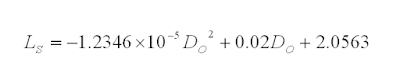
Equation to differentiate Stiff Medium and Medium support (pink line in above graph) is :

Equation to differentiate Medium and Flexible support (yellow line in above graph) is :

The correspondent correction factor (C) for support stiffness level are as follow :
Download
Ref :
1. "Guideline for avoidance of vibration induced fatigue in process work"

Equation to differentiate Stiff Medium and Medium support (pink line in above graph) is :

Equation to differentiate Medium and Flexible support (yellow line in above graph) is :

The correspondent correction factor (C) for support stiffness level are as follow :
- Stiff support ==> C = 4
- Medium Stiff support ==> C =2
- Medium support ==> C =1
- Flexible support ==> C =0.5
Download
Ref :
1. "Guideline for avoidance of vibration induced fatigue in process work"
Related Post
- Assess Potential Piping Failure Due to CV, BDV & PRV Quick Openning with Vapor Discharge
- Assess Potential Piping Failure Due to Valve Quick Opening with Two-Phase Vapor Liquid
- Check Valve Types and Selection
- Anti-surge Control (ASC) or Capacity Control (CC) Valve in Vertical Upward Run ?
- Combine Anti-surge control (ASC) & Capacity Control (CC) Functions ?
- Potential Problem associate with Double NRV in Series within a Line
- Several Strategies To Minimize Relief Capacity in Back-Flow Scenario
Friday, January 1, 2010
Recommended :
- Subscribe FREE - Chemical Engineering
- Tips on Succession in FREE Subscription
Quick closure of valve will results sudden reversal of forward fluid flow and change in velocity. This action will subsequently results sudden momentum changes and lead to severe vibration and peak force act on the piping. In incompressible (liquid) and multiphase (two phase) fluid, it is similar to an accelerate "liquid column" hammering at a wall. The phenomena is commonly known as "water hammer". Water hammer is unlikely to occur in gas / vapor during quick valve closure due to compressible characteristic.
- Subscribe FREE - Chemical Engineering
- Tips on Succession in FREE Subscription
Quick closure of valve will results sudden reversal of forward fluid flow and change in velocity. This action will subsequently results sudden momentum changes and lead to severe vibration and peak force act on the piping. In incompressible (liquid) and multiphase (two phase) fluid, it is similar to an accelerate "liquid column" hammering at a wall. The phenomena is commonly known as "water hammer". Water hammer is unlikely to occur in gas / vapor during quick valve closure due to compressible characteristic.

Quick closure of valve results sudden change in fluid momentum (+mv to -mv) would lead to instantaneous peak force. Similarly, quick opening of valve for incompressible, multiphase and gas/vapor will results sudden change in momentum (0 to +mv) and subsequently instantaneous peak force acting on the piping. This phenomena is commonly occurs in control valve (CV), Blowdown valve (BDV) and pressure relief device i.e. pressure relief valve (PRV) and rupture disc (RD). The instantaneous peak force acting on the piping may potentially lead to piping failure. An assessment method will be presented below to assess the potential failure of piping due to quick opening of valve.
This post will particularly focus on PRV, RD and BDV with gas/ vapor discharge only.
Peak force induced by sudden gas/vapor release
When a valve quick open from FULL Close to FULL Open, instantaneously release gas/vapor from valve upstream piping to downstream piping at choking velocity results peak force (FMax, kN) as :

W = Vapor mass flow (kg/s)
k = Vapor specific heat ratio
Mw = Vapor molecular weight
T = Temperature (K)
Piping Limiting Force
A steel piping with Piping limiting force (FLimit, kN),
with piping wall thickness correction factor,
Do = Pipe external diameter (m)
Di = Pipe internal diameter (m)
Wt = Pipe wall thickness (mm)
WtSch_40 = Schedule 40 pipe wall thickness (mm)
C = Pipe support correction factor
Pipe support stiffness level and correction factor
Pipe support stiffness level and correction factor subjects to support span length (LS) and pipe external diameter (Do) which can be determined from below chart.
Assessment Criteria
To ensure piping will not failed on sudden opening of valve, the following shall be met :
FMax < 0.3 FLimit
In the event FMax is more than 0.3 but less than 0.5 of FLimit, a detail small bore connection checking shall be conducted.
Ref :
1. "Guideline for avoidance of vibration induced fatigue in process work"
Ref :
1. "Guideline for avoidance of vibration induced fatigue in process work"
Related Post
- Assess Potential Piping Failure Due to Valve Quick Opening with Two-Phase Vapor Liquid
- Quick Determination Pipe Support Stiffness Level and Correction Factor
- Check Valve Types and Selection
- Anti-surge Control (ASC) or Capacity Control (CC) Valve in Vertical Upward Run ?
- Combine Anti-surge control (ASC) & Capacity Control (CC) Functions ?
- Potential Problem associate with Double NRV in Series within a Line
- Several Strategies To Minimize Relief Capacity in Back-Flow Scenario
Thursday, December 18, 2008
Display problem ? Click HERE
Recommended :
Subscribe FREE - Processing Magazine
 Water hammer or pipeline surge is one of the phenomenon occur so quick (in mili second) without operator notice and aware that the surge has begun, progressed and ended. It some time lead to pipeline damage , leak and catastrophe.
Subscribe FREE - Processing Magazine
Water hammer or pipeline surge is one of the phenomenon occur so quick (in mili second) without operator notice and aware that the surge has begun, progressed and ended. It some time lead to pipeline damage , leak and catastrophe.Water hammer and transient flows are used synonymously to describe an unsteady flow of fluids in pipelines, although the former term usually refers to water only. Different types of flow variation can contribute to transients, varying from a single identifiable alteration to an oscillating, periodic, or pulsating disturbance. In pumping stations (where rotary pumps with electric drives are used) and water supply systems, transients are normally governed by a change in the operational status of the pumps or valves, by varying demand experienced by the system, or by unpredictable circumstances such as pipeline or power failures.
The following document provides an overview of the theories describing surge phenomena in close conduit systems. Attention is also given to calculation methods used to determine surge pressures. The value of a holistic procedure (Transient Risk Assessment Procedure, TRAP) to determine the possible causes of surge pressures is emphasized and various measures that can be taken to p event excessive pressures are discussed.
Download (thanks to astro)
Related Post
The following document provides an overview of the theories describing surge phenomena in close conduit systems. Attention is also given to calculation methods used to determine surge pressures. The value of a holistic procedure (Transient Risk Assessment Procedure, TRAP) to determine the possible causes of surge pressures is emphasized and various measures that can be taken to p event excessive pressures are discussed.
Download (thanks to astro)
Related Post
- Check Valve Types and Selection
- Potential Problem associate with Double NRV in Series within a Line
- Several Strategies To Minimize Relief Capacity in Back-Flow Scenario
- Flow Element (FE) Upstream or Downstream of Control Valve (CV) ?
- Why a globe valve is located downstream of manual block valve on drain line ?
- How to Select a Check Valve (NRV) Quantitatively ?
- Why bypass Non-Return Valve (NRV) ?
- Potential Problem associate with Double NRV in Series within a Line
- Basis & Tips on Setting Centrifugal Pump "Warming" Recycle Flow
Labels: hydrualic, Piping, Surge
Sunday, November 16, 2008
Display problem ? Click HERE

Recommended :
Subscribe FREE - Processing Magazine
Check valves or Non-return valves (NRV) are normally installed in piping to avoid back flow. Rotating equipment such as pump, compressor, etc will always be equipped with NRV(s) on the discharge to avoid back flow when rotating equipment is shut. Back flow creates severe surging to the rotating equipment and potentially damage the equipment. In certain process system, NRV will be employed to avoid contamination, overheating, etc due to back flow.Check valves or Non-return valves (NRV) is basically an automatic valve open to allow forward flow and close to against reverse flow. In principle, it split into four basic types. There are swing, dual-plate, tilting disc and lifting type. Wrong selection of check valve type can leads to operability problem, leakage and continual maintenance issue.
Lift Check valves
- higher pressure drop is expected.
- equipped with small return spring to facilitate valve closure on reverse flow
- two type of seat. hard seat for for high differential pressure sealing and resilient seat for low differential pressure sealing
- shortest travel length. Fastest response.
- excellent performance for low and/or pulsating flows
- not good for fluid with particles
- Body install horizontal with disc / piston vertically
- Small check valve range from 1/2" to 2" lift piston type check valve
- Prefer operate in full open position
Minimum Recommended Line Velocity, Vmin (ft/s) = 12 SQRT (v)
where
v = Specific Volume of the Fluid (ft3/lb)

Lift Check Valve
Swing Check Valve
- Tight sealing / shut-off
- Low pressure drop
- Susceptible to water hammer
- Not good for low flow and/or pulsating flow
- Vertical (upward flow) & horizontal installation
- Easiest check valve to maintain
- Prefer operate in full open position
Swing check valves should be sized such that the flow velocity in the line is sufficient to hold the disc in the fully open position.
Minimum Recommended Line Velocity, Vmin (ft/s) = 75 SQRT(v)
where
v = Specific Volume of the Fluid (ft3/lb)

Swing Check Valve
Dual plate Check valve
The characteristic of dual plate check valve is pretty same as swing check valve.
- low pressure drop
- Not good for low flow and/or pulsating flow
- Vertical (upward flow) & horizontal installation
- Faster opening and closure compare to swing check valve
- Susceptible to water hammer (lesser than Swing check valve)
- Prefer operate in full open position

Dual Plate Check Valve
Tilting Disc Check Valves
- Fast opening and closing without damage to disc and seat
- Stable at low and pulsating flows
- Moderate pressure drop. Lower than lifting check valve but higher than swing check valve
- Vertical (upward) & horizontal installation
- Moderate tight sealing
- Prefer operate in full open position
Minimum Recommended Line Velocity, Vmin (ft/s) = 24 sqrt (v)
where
v = Specific Volume of the Fluid (ft3/lb)

Tilting Disc Check Valve
Selection Consideration
There are four (4) main criteria shall be considered for the selection of check valve type :
Related Post
There are four (4) main criteria shall be considered for the selection of check valve type :
- non-slam characteristic
- pressure loss
- cost
- application
Comparative rating for each type of check valve have been provided for these criteria (specifically first two technical criteria). These rating will be plotted on a Check Valve Comparative Selection Chart and together budget for final selection. Read more in "Design and Selection of Check Valve".
Related Post
- Several Strategies To Minimize Relief Capacity in Back-Flow Scenario
- How to predict Check Valve Slam ?
- How to Select a Check Valve (NRV) Quantitatively ?
- Why Redundant NRV in Series within a Line ?
- Why bypass Non-Return Valve (NRV) ?
- Potential Problem associate with Double NRV in Series within a Line
- Basis & Tips on Setting Centrifugal Pump "Warming" Recycle Flow
Labels: Fluid Flow, Hydraulic, NRV, Surge
Tuesday, October 21, 2008
Display problem ? Click HERE
Recommended :
Subscribe FREE - Chemical Processing
 Centrifugal compressor is widely used to increase process fluid pressure head to meet process requirement. All centrifugal compressors are equipped with Anti-surge control valve (ASCV) for equipment protective purpose. In many events, This valve may also serve as capacity control valve in order to maintain a specific process parameter.
Subscribe FREE - Chemical Processing
Centrifugal compressor is widely used to increase process fluid pressure head to meet process requirement. All centrifugal compressors are equipped with Anti-surge control valve (ASCV) for equipment protective purpose. In many events, This valve may also serve as capacity control valve in order to maintain a specific process parameter.One of the question being discussed :
Should we locate compressor Anti-surge control (ASC) or Capacity Control (CC) Valve in vertical upward run ?
Should we locate compressor Anti-surge control (ASC) or Capacity Control (CC) Valve in vertical upward run ?
Good engineering practice is to install anti-surge control valve in horizontal run and no low pocket along the inlet and outlet of the control valve to avoid any possible liquid (or solid) accumulation which possibly lead to issues like corrosion, liquid slug, liquid freezing, solid plugging, etc.
Liquid Condensation & Accumulation Causing Corrosion
When ASCV / CCV in close position, vapor with mist liquid may diffuse along the inlet and outlet of ASCV/CCV. Due to heat loss to ambient and/or mist coalescence, mist is possible condensed and accumulated in low pocket and/or downstream of ASCV/CCV downstream on vertical upward run. If the fluid is wet and contains corrosive compounds i.e. Hydrogen Sulfide (H2S), Carbon Dioxide (CO2), low pocket and/or upward run where liquid is accumulated will experience acid corrosion. Pitting and crevice corrosion may be experienced.
Hydrate formation and/or Water Freezing
A fluid with hydrate former and wet, when there is liquid accumulated due to external ambient cooling, there is potential risk of hydrate formation and water freezing. This potential partially or totally clog the recycle line.
Fluid Possibly Crystallization and Solidify
A fluid contain compound possible crystallize and solidify when it is cooled by ambient, when the fluid is cooled by ambient in the stagnant section in recycle line, the fluid is possibly accumulated at low pocket and/or vertical upward run, downstream of ASCV/CCV and crystallized or solidified and plugged the recycle line
Fluid Possibly Crystallization and Solidify
A fluid contain compound possible crystallize and solidify when it is cooled by ambient, when the fluid is cooled by ambient in the stagnant section in recycle line, the fluid is possibly accumulated at low pocket and/or vertical upward run, downstream of ASCV/CCV and crystallized or solidified and plugged the recycle line
Liquid Slugging flow & Induced Vibration
ASCV/CCV is normally closed and liquid is accumulated along the recycle line due to external cooling. In the event of ASCV / CCV open to recycle vapor at compressor discharge back to suction, vapor will push the liquid column flow along the recycle line. This liquid column will be knocking at the ASCV/CCV, bend and tee. Severe slugging and piping vibration may occur and potential damage ASCV/CCV and line.
Thus, it is always recommended to install ASCV / CCV in horizontal run and no low pocket along the inlet and outlet of the control valve that potentially promote corrosion, slugging flow, liquid freezing and solid plugging.
Related Topic
Thus, it is always recommended to install ASCV / CCV in horizontal run and no low pocket along the inlet and outlet of the control valve that potentially promote corrosion, slugging flow, liquid freezing and solid plugging.
Related Topic
- Combine Anti-surge control (ASC) & Capacity Control (CC) Functions ?
- FAQ Related to Control Valves
- Useful Documents Related to Control Valve
- FREE & Reliable Control Valve Sizing Software
- Understand Droop Effect in Self-regulated Control Valve
- WELKER Jet Contorl Valve Handbook
- How to apply valve equation in HYSYS Depressuring ?
Labels: Compressor, Control valve, Surge
Saturday, October 18, 2008
Display problem ? Click HERE
Recommended :
Subscribes to FREE Hydrocarbon Processing
 Control valve is widely used in Oil & gas, refinery, Petrochemical and chemical plant for control purposes of operating parameters i.e temperature, pressure, level, etc. Several articles as compiled in "Useful Documents Related to Control Valve" are pretty useful to many process and chemical engineers.
Centrifugal compressor is widely used to increase process fluid pressure head to meet process requirement. All centrifugal compressors are equipped with Anti-surge control valve (ASCV) for equipment protective purpose. In many events, This valve may also serve as capacity control valve in order to maintain a specific process parameter.
Subscribes to FREE Hydrocarbon Processing
Control valve is widely used in Oil & gas, refinery, Petrochemical and chemical plant for control purposes of operating parameters i.e temperature, pressure, level, etc. Several articles as compiled in "Useful Documents Related to Control Valve" are pretty useful to many process and chemical engineers.Centrifugal compressor is widely used to increase process fluid pressure head to meet process requirement. All centrifugal compressors are equipped with Anti-surge control valve (ASCV) for equipment protective purpose. In many events, This valve may also serve as capacity control valve in order to maintain a specific process parameter.
Anti-surge control valve (ASCV) is one of required equipment protective function for centrifugal compressor. It is used to protect centrifugal compressor from running in surge region, a phenomenon where centrifugal compressor discharge pressure high enough to results reverse flow follow by severe vibration in the compressor chamber. The Anti-surge control valve is recycling discharge gas back to suction to minimize differential pressure across the centrifugal compressor.
Capacity Control valve (CCV) is normally used to maintain a process parameter of a system by recycling excess gas back to compressor suction. Typical process parameters of a system are fix suction pressure, fix discharge pressure and fix differential pressure.
One of the common question raised is :
Should we provide dedicated control valve for anti-surge and capacity control purpose or combine function control valve ?"
 There are several factors lead to separate control valve for dedicate function.
Control Valve Characteristic
This is one of the most important factor to determine if separate control valve is required. For an anti-surge control purpose, the best control valve characteristic is quick opening. However, for capacity control purpose, an equal percentage is mostly used. Thus, this could easy lead to separate control valve with different characteristics used for dedicated function. However, in many occasion, the valve with equal percentage may also serve the purpose of anti-surge control. This is very much subject to compressor characteristic, system operating pressure, system volume, etc. Only way to prove if a single control serve two purpose is Dynamic simulation.
Safety
In many event, the Anti-surge control system together with anti-surge control valve are within a commercial package of compressor. The purpose is to have single point coordination and responsibility and to avoid unnecessary interference. However, using control valve dedicated to Anti-surge control purpose for capacity control purpose would lead to interference and additional signal managing the control valve. Some company safety principle do not allow an protection function used as control function as well. Thus, a separate / dedicate control valve is used. In many recent serious improvement in technology and working method, one control valve serving dual purposes are widely implemented recently.
Wear & Tear
For a control valve serving dual purposes, the control valve may continues in service and this promote wear and tear of the control valve. This would increase the downtime and availability of this control valve. Doubling the control valves will recover the availability again.
Cost
Dedicated control valve for ASCV and CCV is obviously require higher capital investment.
Used of dedicated control valve for anti-surge and capacity control purpose or combine function control valve is subject to case-by-case basis. No one key fit all locks...
Related Topic
Safety
In many event, the Anti-surge control system together with anti-surge control valve are within a commercial package of compressor. The purpose is to have single point coordination and responsibility and to avoid unnecessary interference. However, using control valve dedicated to Anti-surge control purpose for capacity control purpose would lead to interference and additional signal managing the control valve. Some company safety principle do not allow an protection function used as control function as well. Thus, a separate / dedicate control valve is used. In many recent serious improvement in technology and working method, one control valve serving dual purposes are widely implemented recently.
Wear & Tear
For a control valve serving dual purposes, the control valve may continues in service and this promote wear and tear of the control valve. This would increase the downtime and availability of this control valve. Doubling the control valves will recover the availability again.
Cost
Dedicated control valve for ASCV and CCV is obviously require higher capital investment.
Used of dedicated control valve for anti-surge and capacity control purpose or combine function control valve is subject to case-by-case basis. No one key fit all locks...
Related Topic
- FAQ Related to Control Valves
- Useful Documents Related to Control Valve
- FREE & Reliable Control Valve Sizing Software
- Understand Droop Effect in Self-regulated Control Valve
- WELKER Jet Contorl Valve Handbook
- How to apply valve equation in HYSYS Depressuring ?
- Potential Problem associate with Double NRV in Series within a Line
- 12 Features required for Shutdown Valve (SDV)
Labels: Compressor, Control valve, Surge
Thursday, September 4, 2008
Display problem ? Click HERE
Recommended :
- Subscribe FREE - Chemical Engineering
- Tips on Succession in FREE Subscription

In earlier post "Complicated Tube Rupture Scenario... Nightmare in Sizing a PRD" related to complication of a tube rupture involving many relieving combination. This is a great challenge to a Pressure Relief Device (PRD) designer to provide a correctly sized PRD. For a heat exchanger with low pressure liquid on shell side and high pressure liquid on tube side, pressure surge in one of the thread as discussed in "Tube Rupture : Pressure Relief Valve (PSV) or Rupture Disk (RD) ?"
- Subscribe FREE - Chemical Engineering
- Tips on Succession in FREE Subscription
In earlier post "Complicated Tube Rupture Scenario... Nightmare in Sizing a PRD" related to complication of a tube rupture involving many relieving combination. This is a great challenge to a Pressure Relief Device (PRD) designer to provide a correctly sized PRD. For a heat exchanger with low pressure liquid on shell side and high pressure liquid on tube side, pressure surge in one of the thread as discussed in "Tube Rupture : Pressure Relief Valve (PSV) or Rupture Disk (RD) ?"
However, once the rupture is bursted, continuous liquid feeding flare system could be a difficult issue. What can be done ?
The are some ways may consider to handle this situation. The following is one of the way can be considered but still require proper engineering and HAZOP analysis before implementation.

It is recommended to provide a surge vessel on the outlet of rupture disc to capture short term liquid flow. On the surge vessel, there will be a pressure relief valve connected to flare. Apart, provide High-High level trip (LZHH) with two-out-of-three (2oo3) voting on the surge vessel in order to shutdown all the high pressure source.
With above configuration, in the event of tube rupture, high pressure liquid will leak into low pressure side in shell side. Surge pressure may cause rupture disc burst and liquid will discharge into surge drum. Liquid level in surge drum will built up, trigger High-High level trip (LZHH) in surge drum and initiate all Shutdown valves (SDV) closure. This will stop catastrophic failure due to surge pressure and liquid disposal problem.
One shall take note above shutdown configuration may not have proper SIL level for protection. It need further improvement and proper configuration.
Related Topic
One shall take note above shutdown configuration may not have proper SIL level for protection. It need further improvement and proper configuration.
Related Topic
- Criteria for Requirement of Pressure Relief Device for Tube Rupture
- Tube Rupture : Pressure Relief Valve (PSV) or Rupture Disk (RD) ?
- Requirement of Overpressure Protection Device on "Final Vessel"
- FREE & reliable Pressure Relief Valve Sizing Software
- Extra Caution When Eliminating Overpressure by Fire Attacks
- Should maximum recommended wall temperature (Tw) for carbon steel vessel used as design temperature ?
- Should we install Butterfly valve for Pressure Relief Valve (PSV) isolation ?
Labels: Overpressure Protection, Pressure Relief Device, Surge
Tuesday, May 27, 2008
Display problem ? Click HERE
Discussion in "How to predict Check Valve Slam ?" has shown potential of surge pressure if a normal check valve is provided in the pump discharge. Nevertheless, in many design the surge pressure could be within the allowable limit of piping short term pressure spike. Thus, it is "normally" that providing a normal check valve on pump discharge does not poses any danger of pressure surge. Having said this, a proper checking should be carried out.
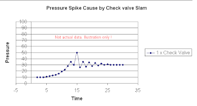
One of the scenario that has been warned for many times is providing double check valves in the pumping system. With single normal check valve in the pump discharge line, the discharge may experience a short term pressure spike as shown in image below.
In case of double check valves in the pumping system, there may be a very short time gap between the closure of both check valves. This would allow both check valves generate two pressure waves running forward and backward along the pumping system. Two waves would probably meet along the piping. Both waves' amplitude could be added or subtracted between each and other subject to wave's pattern. A severe pressure spike could be additional of two identical waves as shown in the following image.
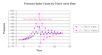
Above discussed about the potential of severe pressure spike in the pumping system with double check valves, however, it very subject to :
- Shutdown valve closure time
- Pump shutdown time and its impact on the pressure waves
- Piping length
- Location of the check valves
- Check valves type and its closure time
thus, providing double check valves does not mean severe pressure spike will definite happen. However, the potential of severe pressure spike increases as well as it associate risk. Only proper pressure surge study and review on the wave and pressure spike pattern can advise the likelihood of occurrence.
Related Post
- How to predict Check Valve Slam ?
- How to Select a Check Valve (NRV) Quantitatively ?
- Why Redundant NRV in Series within a Line ?
- Why bypass Non-Return Valve (NRV) ?
- Tips for Centrifugal Pump
Labels: Fluid Flow, Hydraulic, NRV, Surge
Wednesday, March 19, 2008
Display problem ? Click HERE
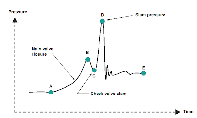
Check valve slam is one of the common problem encounter in rotating equipment discharge e.g pump, compressor, etc. As mentioned in earlier post "How to Select a Check Valve (NRV) Quantitatively ?" one of the requirement is for a "good" check valve is non-slam characteristic.
For a pumping system with a check valve installed on the discharge, whenever the pump is shut, reverse flow is formed quickly and approaching check valve. One of the requirement to avoid check valve slam is the check valve shall be closed faster than the reverse flow acting on the disc. You may the following animation and see how a check valve with the disc closure is faster than the reverse flow and avoid damage of check valve and severe surge pressure.
As the closure of valve disc is affected by few factor such as disc travel distance, reverse flow travel length, etc. How should you predict if a check valve would experience slam and severe surge ?
A methodology for predicting check valve slam is one of the article you may read to identify if a selected check valve would experience slam during closure time.
Related Post
Courtesy of DFT (click to visit)
As the closure of valve disc is affected by few factor such as disc travel distance, reverse flow travel length, etc. How should you predict if a check valve would experience slam and severe surge ?
A methodology for predicting check valve slam is one of the article you may read to identify if a selected check valve would experience slam during closure time.
Related Post
- How to Select a Check Valve (NRV) Quantitatively ?
- Why Redundant NRV in Series within a Line ?
- Why bypass Non-Return Valve (NRV) ?
- Pump Pressure Versus Head
- Why Centrifugal pump NPSH required increases with flow ?
- Tips for Centrifugal Pump
- Rule-of-thumb For Minimum Flow Recycle
- Restrcition Orifice Used in Many Applications in Different Manners
