Sunday, April 12, 2009
Display problem ? Click HERE
Recommended :
 Many real life experiences have shown that if valves are not work or stroke for substantial period, they may failed to work (stuck at preset position) when it is on demand. This is particular critical to safety related valves i.e. Emergency shutdown (ESD) valve, blowdown (BDV) valves, pressure dump valves, etc and potentially lead catastrophe event. Valve reliability and availability is extremely critical and important in a safety system. Functional test of these valves during operation is required to main valves reliability and availability while maintaining zero / minimum production downtime. One of the testing method is on-line Partial Stroke Testing (PST), which is particular suitable for ESD valves, as well as other critical valves. PST—supplemental testing offers a method of testing the valve by moving it, typically 15-25%, and back to the original position in a short period of time in order to confirm the valve’s ability to move (not stuck in place) and its suitability for continued safety instrumented system (SIS) service.
 A PST with dedicated testing interval improve a Safety Integrity Level (SIL) level of a particular SIS system. For example, a typical one-out-of-one (1oo1) ball valve with 1oo1 solenoid (Proof test, PT interval of 1 year, the average Probability of Failure on Demand (PFDavg) is about 2.25 x 10⁻², this lead to SIL of 1.65. With a PST, it improve the PFDavg to 7.36 x 10⁻³, equivalent to SIL of 2.13 with typical PFDavg Reduction of 67%. Detail refer to "Valve Failure :Not an Option". This sometime is important and useful during plant revamping and modification. For example, present SIS system demand only SIL 1 . Plant revamping and modification results SIL 2 demand. Inclusion of PST would make SIS system sufficient.
Related Topic
Labels: Emergency Shutdown, Loss Prevention


Thursday, May 22, 2008
Display problem ? Click HERE
Kunal, a student from India has asked a rather simple question.
What is the function of VALVE ?
This question has triggered me to take a little effort to tabulate :
i) Isolation
Valve has been commonly used for system isolation and positive protection i.e. shutdown valve. Valve used for isolation purposes generally are ball, gate and butterfly.
ii) Throttling & control
Varying opening of flowing path area in valve would be able to limit quantity of fluid passing the valve and serve the throttling and control purposes. Valve used for throttling and control purposes generally are globe, needle, special designed control valve, etc.
iii) Overpressure & Vacuum protection
Valve also use for system overpressure & vacuum protection. For overpressure protection, fluid is contained in system during normal operation. Whenever the system pressure increase, the valve will open to relief fluid to ensure system pressure below maximum allowable working pressure of the system. Valve use for his purpose is generally spring loaded pressure relief valve and pilot-operated pressure relief valve. Similar principle apply to vacuum protection but the difference is only allowing fluid enter into system to avoid vacuum.
iv) Avoid back flow
Valve with piston, flapper, etc would allow fluid flowing forward. Whenever fluid flow backward, the piston & flapper will close the flow path and restrict fluid back flow. Valve is normally called check valve or non-return valve.
v) Pump minimum flow protection
Valve like ARC valve is a self-contained valve which contain the check valve feature while allowing flow diversion during low flow. This is a good combination in pumping system where it demand back flow protection to avoid impeller damage and minimum flow protection during low flow.
Related Topic
Related Topic
Labels: Control valve, Emergency Shutdown
Tuesday, May 20, 2008
Display problem ? Click HERE
A centrifugal pump feeding liquid to a heat exchanger located downstream. Check valve is provided between pump and heat exchanger to avoid back flow damaging the pump impeller. As the heat exchanger design pressure is lower than the pump shut-in pressure, A pressure relieve valve (PRV) is provided just upstream of the heat exchanger to avoid overpressure during pump shut-in condition. A shutdown valve (SDV) is located downstream of the heat exchanger for system isolation purpose. Both heat exchanger and SDV are located at one deck (~ 10m) higher than the pump. In the event of system shutdown, the Emergency Shutdown System (ESD) will initiate shut close of SDV and pump stop. Above arrangement is pretty standard in Chemical plant or Oil & gas plant.
When the system is commissioned and put under operation, everything run smooth. Nevertheless, the PRV open and slam close whenever the system shutdown. What was the problem ?
Why PRV passing during shutdown?
After some level of analysis, the following were postulated :
i) Whenever the system (pump & SDV) shutdown, the closure of SDV and lead to incompressible liquid back flow to check valve (in wave motion). The check valve slam (ordinary check valve) and lead to forword wave . The forward and backward wave would subsequently lead to pressure spike in the line and resulting opening of PRV. Read "How to predict Check Valve Slam ?" to get more insight into how ordinary check valve lead to pressure spike.
ii) As the heat exchanger and SDV is located ~ 10m above the pump & check valve, whenever the pump stop and check valve closure, liquid column would induce back flow and further increase the pressure spike.
iii) Pump rotate in forward direction would have substantial inertial and take longer time from full speed to zero speed. However, SDV would have much shorter closing time from full open to full close position. Apart from pressure spike caused by the ordinary check valve & SDV, the reducing forward flow would further increase the potential of pressure spike.
All aboves lead to pressure spike and potential lifting PRV.
How to avoid ?
Few approaches may be considered to minimize / avoid above situation :
a) Conduct surge analysis and check the potential of pressure spike
b) Use Non-Slam Check valve (if requried). Read "How to predict Check Valve Slam ?"
c) Increase SDV closing time. Read "Maximum Allowable Time from Shutdown Initiation to SDV Fully Closed" for maximum SDV closing time.
d) Use surge suppressor.
Related Post:
- How to predict Check Valve Slam ?
- Maximum Allowable Time from Shutdown Initiation to SDV Fully Closed
- A Technical Report for Partial Stroke Testing of Automated Block Valves
- Partial Stroke Testing for Emergency Shutdown Valves
- Requirements of SDV Bypass Pressurization Line
- 12 Features required for Shutdown Valve (SDV)
Labels: Emergency Shutdown, Pressure Relief Device, Pump
Monday, April 21, 2008
Display problem ? Click HERE
Shutdown Valves (SDV) are commonly use in oil and gas production system for safe and proper isolation purpose to minimize escalation of hazardous from one system to another system.
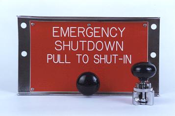
In "12 Features required for Shutdown Valve (SDV)", one of the requirements of SDV is Fast Action.
What is the maximum allowable time from shutdown initiation to SDV fully closed ? Any code or standard can be referred ?
According to API RP 14C, 7th Edition, March 2001, "Recommended Practice for Analysis, Design, Installation, and Testing of Basic Surface Safety Systems for Offshore Production Platforms" Appendix C - Support Systems C.2.1.4. "The time it takes for any safety device (e.g. PSH, BSL, ESD station, etc.) to effect component or platform shutdown should not exceed 45 seconds."
Thus, the upper limit is 45 second. However, quick closing SDV would also lead to transient surge. It is recommended the closing time should be minimum 3-5 second. This is just a recommendation. For a piping which is long, low ductility, carrying incompressible fluid, etc, it increases the potential of pipe failure due to surge. A proper surge analysis may be conducted if it is deem necessary.
Related Post:
In "12 Features required for Shutdown Valve (SDV)", one of the requirements of SDV is Fast Action.
A shutdown valve shall act fast to minimize the escalation of hazards. Generally a quarter ball valve is the excellent device in quick action. As rule of thumb, shutdown valve shall be capable of begin it closing action within 10 seconds of activation, and time taken from Full open to Full Close is within 1-2 seconds per inch of shutdown valve size. However, this shall be compliant to overall safety philosophy.
What is the maximum allowable time from shutdown initiation to SDV fully closed ? Any code or standard can be referred ?
According to API RP 14C, 7th Edition, March 2001, "Recommended Practice for Analysis, Design, Installation, and Testing of Basic Surface Safety Systems for Offshore Production Platforms" Appendix C - Support Systems C.2.1.4. "The time it takes for any safety device (e.g. PSH, BSL, ESD station, etc.) to effect component or platform shutdown should not exceed 45 seconds."
Thus, the upper limit is 45 second. However, quick closing SDV would also lead to transient surge. It is recommended the closing time should be minimum 3-5 second. This is just a recommendation. For a piping which is long, low ductility, carrying incompressible fluid, etc, it increases the potential of pipe failure due to surge. A proper surge analysis may be conducted if it is deem necessary.
Related Post:
- A Technical Report for Partial Stroke Testing of Automated Block Valves
- Partial Stroke Testing for Emergency Shutdown Valves
- Requirements of SDV Bypass Pressurization Line
- 12 Features required for Shutdown Valve (SDV)
Labels: Emergency Shutdown, Overpressure Protection
Saturday, April 5, 2008
Display problem ? Click HERE
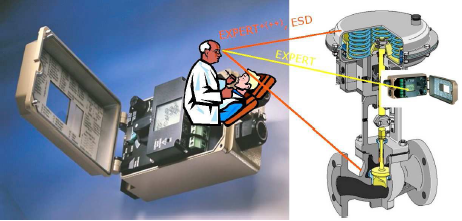
Partial stroke test is one of the testing procedures to ensure reliability and availability of valves. This kind of test is required for critical valve and it helps to increase confident level and Safety Integration Level (SIL) of critical valves. Partial stroke testing identifies failure modes associated with the block valve actuator and a limited number of failure modes associated with the valve body or internals (e.g., valve stem damage and stem to valve connection).
A newly completed technical report, ISA-TR96.05.01-2008, Partial Stroke Testing of Automated Block Valves, addresses
A newly completed technical report, ISA-TR96.05.01-2008, Partial Stroke Testing of Automated Block Valves, addresses
- the applications when partial stroke testing may be useful
- the various methods used for partial stroke testing
- the advantages and disadvantages of each technology.
Related Post:
- Partial Stroke Testing for Emergency Shutdown Valves
- Should we install Butterfly valve for Pressure Relief Valve (PSV) isolation ?
- Requirements of SDV Bypass Pressurization Line
- Controlled and Non-controlled Type Depressuring.
- How to apply valve equation in HYSYS Depressuring ?
- 12 Features required for Shutdown Valve (SDV)
Labels: Emergency Shutdown, Safety
Thursday, November 15, 2007
There are many real life experiences have shown that if valves are not work for substantial period, they can stick in the preset position. Past experiences also showed that once it is stuck at one position, system may experience difficulties to move from preset position and sometime failed to move it. Valve sticking / stuck at preset position could be cause by dirt accumulation, corrosion debris, corroded shaft break, etc.
On the hand, valves continuous move from one position to another position (e.g. full close to full open and vice versa) will minimize the chances of dirt and corrosion debris accumulation and get harden. A continuous moving valve with constant monitoring of it stroking time will enable alert of a out perform valve.
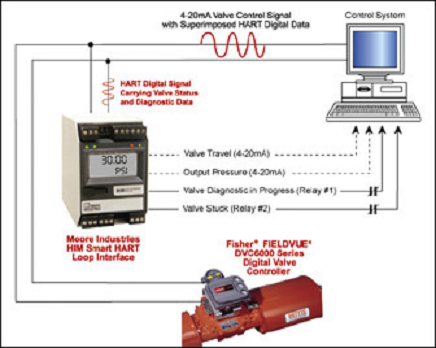
Partial stroke test is one of the testing procedures to ensure reliability and availability of valves. Normally the test is required for critical valve such as battery limit Emergency Shutdown Valves (ESDV). In addition, it helps to increase confident level and Safety Integration Level (SIL) of critical valves. Partial stroke test can be conducted manual by trained personnel and the testing can also be automated (PLC based) to minimize human error.
Nevertheless, there are some disadvantages of partial stroke test. Frequent testing of these valves promotes wear and tear and increases potential leakage and failure.
Following are some articles related to Partial Stroke Testing and you are encourages to read to enhance further your understanding.
On the hand, valves continuous move from one position to another position (e.g. full close to full open and vice versa) will minimize the chances of dirt and corrosion debris accumulation and get harden. A continuous moving valve with constant monitoring of it stroking time will enable alert of a out perform valve.
Partial stroke test is one of the testing procedures to ensure reliability and availability of valves. Normally the test is required for critical valve such as battery limit Emergency Shutdown Valves (ESDV). In addition, it helps to increase confident level and Safety Integration Level (SIL) of critical valves. Partial stroke test can be conducted manual by trained personnel and the testing can also be automated (PLC based) to minimize human error.
Nevertheless, there are some disadvantages of partial stroke test. Frequent testing of these valves promotes wear and tear and increases potential leakage and failure.
Following are some articles related to Partial Stroke Testing and you are encourages to read to enhance further your understanding.
- Need for an industry standard for ESD valves from engineering & safety point of view
- Partial Stroke Testing ESDV
- Partial Stroke Testing - Good & Bad and the Ugly
- The Partial Stroke Test as a module in the process safety concept
- Achieving High SIL Ratings with Partial Stroke Testing of Valves
- Should we install Butterfly valve for Pressure Relief Valve (PSV) isolation ?
- Another descrepancy found in API Std 521Jan 2007
- Controlled and Non-controlled Type Depressuring.
- How to apply valve equation in HYSYS Depressuring ?
- 12 Features required for Shutdown Valve (SDV)
- ERRATA - API Std 521, Pressure Relieving and Depressuring Systems
Labels: Emergency Shutdown, Safety
Tuesday, November 6, 2007
Oil and gas facilities is generally required to be depressured to a safe level within a reasonable time during emergency situation. The requirements are clearly stated in the API Std 521 2007 edition, section 5.20.1.
In earlier post "How to apply valve equation in HYSYS Depressuring ?"
In earlier post "How to apply valve equation in HYSYS Depressuring ?"
where i have discussed what, where and how to apply vapor flow equations in the HYSYS Depressuring valve parameter page. In that posts, i have mentioned about controlled and non-controlled type depressuring but without detailing them. In this i will elaborate a bit more the function and application of controlled and non-controlled type depressuring.
Non-controlled Type Depressuring
Non-controlled type is the most ordinary type of depressuring arrangement. Generally it consists of a Blowdown Valve (BDV) for isolation purpose with a correctly sized restriction orifice (RO) to limit peak depressuring rate.

Non-controlled type depressuring is commonly apply throughout plant depressuring system. It can depressure the system from initial pressure (Pi) to final pressure (Pf) within required time frame (i.e. 15 minutes). As it is a fixed bore restriction orifice, the initial depressuring rate is high and gradually decrease to minimum depressuring rate at the final condition.
This arrangement is conventional, simple and reliable for most depressuring system without any process or equipment limitation.
To model this type of depressuring in HYSYS rather simple, i would always propose to use the [General] vapor flow equation for critical flow case and [Subsonic] vapor flow equation for subcritical case.
Controlled Type Depressuring
For some systems such as compressor and mole sieve bed, the depressuring rate needs to be controlled in order to avoid damage of compressor seal and mole sieve bed. This requirement generally imposed by the equipment supplier to the client and they generally limit the rate of pressure drop e.g 20 bar / min for compressor seal, 50 psi/ min for mole sieve bed, etc. With this additional requirement, an ordinary non-controlled type depressuring (single BDV+RO) may not meet both requirements. It could either meeting the 15 minutes depressuring time but with high rate of pressure drop during initial depressuring or meeting the rate of pressure drop but with extended depressuring time (>15 minutes). A controlled type depressuring method is required.
First type would be multiple BDV with RO (smaller). See below image.

The idea is to provide small opening for depressuring during initial depressuring, as the system pressure is reduced, the opening for depressuring is gradually rise to increase the depressuring rate. Opening of BDVs will be staggered according to time in order to limit the rate of pressure drop whilst depressuring the system pressure within the required time (i.e. 15 minutes). The method is step change of opening and depressuring rate will change from time to time but within a flow rate band.
Second type would be a flow control valve with a flow control loop. See below image.
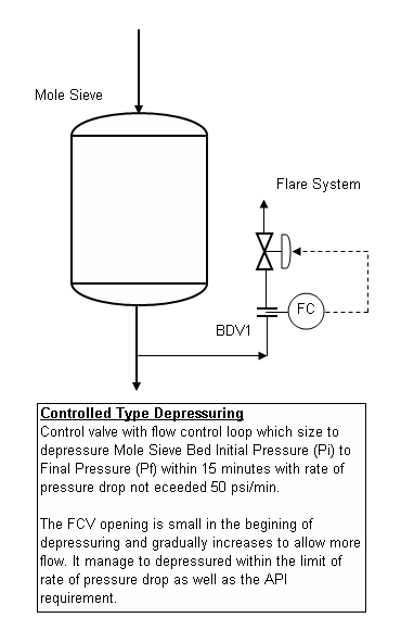
It basically to maintain a constant depressuring rate by varying the valve opening. It can limit the rate of pressure drop whilst depressuring the system pressure within the required time (i.e. 15 minutes). It can maintain a rather constant flow throughout the entire depressuring period, however reliability could be a major issue in most application.
To model the first type of controlled depressuring using multiple BDV & RO in HYSYS is rather complicated. Presently (version 2006) there is no multiple depressuring unit is available in HYSYS. I would propose to conduct series of batch depressuring (similar to single BDV+RO case) with different orifice size.
To model the second type of controlled depressuring using FCV, it is proposed to use the vapor flow equation of [Fisher] and [Masoneilan] may be applied. This involve trial-and-error to find a suitable control valve module to facilitate the depressuring rate.
Further Reading :
Non-controlled Type Depressuring
Non-controlled type is the most ordinary type of depressuring arrangement. Generally it consists of a Blowdown Valve (BDV) for isolation purpose with a correctly sized restriction orifice (RO) to limit peak depressuring rate.
Non-controlled type depressuring is commonly apply throughout plant depressuring system. It can depressure the system from initial pressure (Pi) to final pressure (Pf) within required time frame (i.e. 15 minutes). As it is a fixed bore restriction orifice, the initial depressuring rate is high and gradually decrease to minimum depressuring rate at the final condition.
This arrangement is conventional, simple and reliable for most depressuring system without any process or equipment limitation.
To model this type of depressuring in HYSYS rather simple, i would always propose to use the [General] vapor flow equation for critical flow case and [Subsonic] vapor flow equation for subcritical case.
Controlled Type Depressuring
For some systems such as compressor and mole sieve bed, the depressuring rate needs to be controlled in order to avoid damage of compressor seal and mole sieve bed. This requirement generally imposed by the equipment supplier to the client and they generally limit the rate of pressure drop e.g 20 bar / min for compressor seal, 50 psi/ min for mole sieve bed, etc. With this additional requirement, an ordinary non-controlled type depressuring (single BDV+RO) may not meet both requirements. It could either meeting the 15 minutes depressuring time but with high rate of pressure drop during initial depressuring or meeting the rate of pressure drop but with extended depressuring time (>15 minutes). A controlled type depressuring method is required.
First type would be multiple BDV with RO (smaller). See below image.
The idea is to provide small opening for depressuring during initial depressuring, as the system pressure is reduced, the opening for depressuring is gradually rise to increase the depressuring rate. Opening of BDVs will be staggered according to time in order to limit the rate of pressure drop whilst depressuring the system pressure within the required time (i.e. 15 minutes). The method is step change of opening and depressuring rate will change from time to time but within a flow rate band.
Second type would be a flow control valve with a flow control loop. See below image.
To model the first type of controlled depressuring using multiple BDV & RO in HYSYS is rather complicated. Presently (version 2006) there is no multiple depressuring unit is available in HYSYS. I would propose to conduct series of batch depressuring (similar to single BDV+RO case) with different orifice size.
To model the second type of controlled depressuring using FCV, it is proposed to use the vapor flow equation of [Fisher] and [Masoneilan] may be applied. This involve trial-and-error to find a suitable control valve module to facilitate the depressuring rate.
Further Reading :
- How to apply valve equation in HYSYS Depressuring ?
- 6 elements & factors lead to high quality question
- Carefully assess information in the web
- 12 Features required for Shutdown Valve (SDV)
- ERRATA - API Std 521, Pressure Relieving and Depressuring Systems
- Requirement of overpressure protection devices on system design to PIPING code
Labels: Depressurization, Emergency Shutdown, HYSYS
Thursday, October 25, 2007
High pressure and moderate/low temperature operation are common in oil and gas industry. High pressure system with large vessels will lead to large inventory and it significantly increases hazardous level to personnel and assets. Thus, API Std 521 has stated clearly and requested plant emergency response system to depressurize the system from it maximum operating pressure to 50% of it design pressure or 6.9 barg, whichever is lower within 15 minutes. The intention is to evacuate the inventory within an acceptable time limit to minimize risk of secondary hazard to personnel / assets and provides sufficient time for personnel evacuation.
Depressurization study is one of the mandatory studies in oil and gas for long time. Thus process simulator common used in oil & gas such as HYSYS, PRO-VISION, etc have built-in depressuring module which specifically sued for depressurization study. HYSYS has been in the market for more than 15 years and it is well accepted by many users as it commonly known with its “real time” information and user friendly interface. One of section within the depressuring unit where user needs to provide information is the depressuring valve parameter page. The valve parameter page is basically to define the characteristic and vapor flow equation of depressuring device. Users are free to choose those seven (6) vapor flow equations (built-in), There are :
Depressurization study is one of the mandatory studies in oil and gas for long time. Thus process simulator common used in oil & gas such as HYSYS, PRO-VISION, etc have built-in depressuring module which specifically sued for depressurization study. HYSYS has been in the market for more than 15 years and it is well accepted by many users as it commonly known with its “real time” information and user friendly interface. One of section within the depressuring unit where user needs to provide information is the depressuring valve parameter page. The valve parameter page is basically to define the characteristic and vapor flow equation of depressuring device. Users are free to choose those seven (6) vapor flow equations (built-in), There are :
- Fisher
- Masoneilan
- Relief valve
- Supersonic
- Subsonic
- General
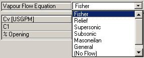
HYSYS default is [Fisher]. User may view the equations used for each of them by clicking the “Valve Equation Help…” button. See following image.

Out of 6 vapor flow equations, which equation shall be chosen and applied ?
HYSYS recommends to used [Fisher] and [Relief] as these equations are more advanced than other valve equation. No doubt these equations are established and well accepted by many users. How shall these equations be applied in different kind of systems ?
In my point of view, [Fisher] and equations will be used when controlled depressuring system. Common controlled depressuring application are depressuring of compressor and Mole-Sieve bed. It is very common the manufacturer of this equipment impose maximum pressure drop-rate (kPa/min) to protect their equipment. User may needs to selected a good control valves to limit the maximum pressure drop-rate whilst meeting maximum depressuring time limit of 15 minutes.
For non-controlled depressuring system, other equations such as may be used. equation is recommended by HYSYS and can be used by setting the set pressure lower the FULL OPEN pressure (REMEMBER : Both setting shall be lower than the maximum expected pressure. Otherwise the valve will not “open”). I guess the main issue here is to provide the discharge coefficient (Kd) for orifice. Personally there may be some document out there which has recommended what type of Kd factor to be used. If any of user aware of it, please share in the comments column.
equation basically is a derivation from the equation by considering Kterm and k equal as unity. This equation may be used in non-controlled depressuring system and it is for critical flow condition where backpressure is lower than system pressure. User may use this equation if the fluid characteristic is not well defined. User shall take note that there is a possibility where initial depressurization will be in critical flow condition and towards the end, backpressure may be exceeded the critical pressure. This will result some level of inaccuracy. This is very unlikely event and generally it is ignored.
equation is an equation which common used in non-controlled depressuring system and to handle subcritical flow system (backpressure higher than system pressure). This is the only equation built into HYSYS which can handle subcritical condition (as far as I aware but I guess and may be capable). HYSYS has not documented this. Thus it is not recommended to use.
[General] equation is a well accepted equation which has been extracted from PERRY’s Chemical Engineering Handbook. The only parameters user required to input are the orifice Discharge Coefficient (Cd) and Orifice area (A). As in most of the case, a square-edged restriction orifice is applied for depressuring, (downstream of Blowdown valve, BDV), the discharge coefficient (Cd) is well defined in . See following image.
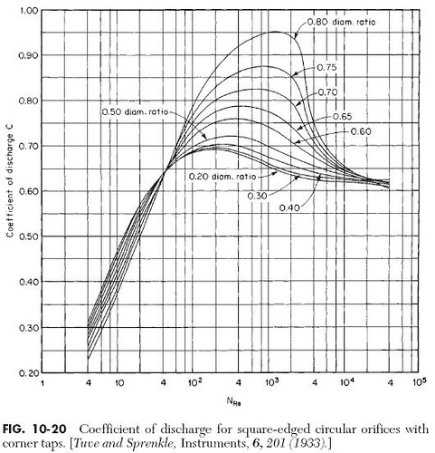
Generally the Reynolds number at the orifice throat is higher than 10,000, thus the Discharge coefficient is in the range of 0.6 to 0.65. Beware that HYSYS has recommended the used of 0.7 to 1.0. This may be true when the Reynolds number is in the range of 100 to 10,000. User shall always check at the end of study. Personally I would recommend to us 0.6 and reconfirm with Reynolds Number check by end of run. One shall remember this equation is applicable to Critical flow condition only. As in most cases, plant emergency depressuring will be critical flow, i am recommending to use this equation when you are dealing with non-controlled depressuring.
You comments and advices are welcome.
HYSYS recommends to used [Fisher]
In my point of view,
For non-controlled depressuring system, other equations such as
Generally the Reynolds number at the orifice throat is higher than 10,000, thus the Discharge coefficient is in the range of 0.6 to 0.65. Beware that HYSYS has recommended the used of 0.7 to 1.0. This may be true when the Reynolds number is in the range of 100 to 10,000. User shall always check at the end of study. Personally I would recommend to us 0.6 and reconfirm with Reynolds Number check by end of run. One shall remember this
You comments and advices are welcome.
Further Reading :
Labels: Depressurization, Emergency Shutdown, HYSYS
Saturday, October 20, 2007
Shutdown Valves (SDV) are common apply in oil and gas production system for safe and proper isolation purpose to minimize escalation of hazardous from one system to another system. General shutdown valve is controlled by a high integrity Emergency Shutdown System (ESDS).
A shutdown valve shall equipped with the following features :
i) Tie Shut Off (TSO)
- Zero/minimum leakage shall be expected for a device act as shutdown valve. Generally a Shutdown valve seat leakage shall pass the seat leakage testing per API 508 and/or ISO 5208.
ii) Firesafe
- shutdown valve is expected to work promptly even though it expose to external fire attacks. thus, shutdown valve body shall be fire rated according to API 607 for soft seated valve or API 6FA for API 6A & API 6D valves or BS 6755 Part 2.
iii) Fast action (From Full Open - Full Close)
- A shutdown valve shall act fast to minimize the escalation of hazards. Generally a quarter ball valve is the excellent device in quick action. As rule of thumb, shutdown valve shall be capable of begin it closing action within 10 seconds of activation, and time taken from Full open to Full Close is within 1-2 seconds per inch of shutdown valve size. However, this shall be compliant to overall safety philosophy. Proper selection and sizing of actuator to ensure above requirements are fulfilled.
iv) Minimum passing (during closing of shutdown valve)
- The feature is required to minimize the potential of overpressure of Low pressure system and spurious trip. A shutdown valve with equal% characteristic (most ball valve will have this feature. However, this shall be confirmed with valve supplier) is preferred type. With equal% characteristic, it can operate with 10% valve closure give 20% flow reduction, 20% closure give 50% closure...the closure of valve is fast and minimize inventory passing.
v) Minimum disturbance / turbulence to process fluid
- This feature is to minimize unnecessary energy lost. Reduced Bore (RB) ball valve having hole in the middle would minimize flow direction change and turbulence. Full Bore (FB) ball valve virtually like a pipe- significantly minimize energy lost.
vi) Fail-safe
- A shutdown valve actuator shall pneumatic/hydraulic fail-safe spring-return type. Generally a shutdown valve failed to close (FC). Electrical driven type shall not be used.
vii) Manual field reset
- A shutdown valve shall be reset manual at field. The operator shall ensure the system is clear and safe and reset on site. No remote reset is allowed.
viii) Clear physical indicator
- Shutdown valve shall be equipped with visible external valve position indicators to provide clear positioning and status of a shutdown valve.
ix) Position switches
Position switches shall be provided on shutdown valve to provide clear positioning and status of a shutdown valve to control room.
x) Partial Stroke Testing of Shutdown Valve
A shutdown valve in critical service e.g. Pipeline outgoing and incoming shutdown valve (ESDV) will required periodically partial stroke testing in order to maintain / increase it reliability, availability & SIL level.
xi) Accumulator
Some shutdown valve may be equipped with accumulator to facilitate valve stroking and /or reopen in the event maloperation.
xii) Second Solenoid valve
Shutdown valve in critical service may be equipped with second solenoid valve to increase reliability and availability.
Above has presented 12 features of shutdown valve. Some operating company may have their additional requirements and limitation on shutdown valve.
Related topics
- ERRATA - API Std 521, Pressure Relieving and Depressuring Systems
- Requirement of overpressure protection devices on system design to PIPING code
- ESD Selection Guide, Metso Automation, Issue 4/2001
- Partial Stroke Testing of Emergency Shutdown Valves, ACM Automation
- Achieving High SIL Ratings with Partial Stroke Testing of Valves, ACM Automation
Labels: Emergency Shutdown, Loss Prevention, Overpressure Protection, Safety
