Sunday, August 26, 2007

This question has been raised by many engineers and debated in many discussion.
Careful review on the relief valve structure, process fluid passing through a nozzle instead of an orifice. Those many researchers such as Dr. Ron Darby for multiphase flow in Direct Integration method (HDI), Dr Fauske & Dr Henry for two phase relief in Homogeneous Non-equilibrium model (HNE), Dr. Joseph Leung for two phase flow in Omega method, etc have modelled a relief valve as a nozzle.
Classical and conventional studies informed us that vena contracta (VC) will only occur in sharp edge orifice. However, the flow restricting area in a relief valve as decribed by many well knowed specialists is not an orifice, but is actually a nozzle. Thus there is NO vena contracta downstream of the nozzle.
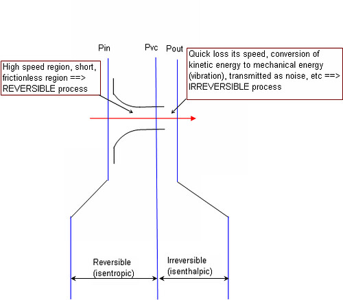
Phenomenon of flow through a nozzle in relief valve is extremely fast. Choked flow is possible occur in some location "A" in the nozzle instead of outside the nozzle (may be closed to the exit end), from the inlet to "A" will be a REVERSIBLE process which generally accepted by most of the specialists. Thus, it is ISENTROPIC process. From location "A" to PSV outlet, the system is expanded and change in state. It will be slow down. There will be transformation energy loss however the enthalpy is maintain constant (ISENTHALPIC). This process is IRREVERSIBLE. "A" is viewed as vena contracta in the relief valve's nozzle. Those in sizing a relief valve, we ignore the frictional loss in the nozzle and consider ISENTROPIC process. However, from expansion process via safety valve (Vena contracta to relief outlet), the process will be ISENTHALPIC.
Related topics
If you benefits from this post, buy me some sweets
Labels: Modelling, Pressure Relief Device, PSV, Thermodynamic


Friday, August 10, 2007

Back pressure is seriously affects the operational and capacity of Pressure Relief valves (PRV/PSV). As the backpressure to spring loaded direct acting PSV (conventional type) is increased, the driven force which is a function of differential pressure across a PSV will drop and reduce the ability to flow across the PSV. impact on flow capacity is minimal as long as the back pressure is below it critical pressure.
Another phenomenon which common understood by everyone is that as the backpressure is increased, additional force apply on the PSV disc and reduce disc lift, it reduce discharge capability. This clearly explained in figure 22 in API RP 521 Part-I.
Another phenomenon which common understood by everyone is that as the backpressure is increased, additional force apply on the PSV disc and reduce disc lift, it reduce discharge capability. This clearly explained in figure 22 in API RP 521 Part-I.

However, the impact is insignificant at low backpressure. API 521 Part-I has recommended that in a conventional PSV application, built-up backpressure SHOULD NOT exceed 10% of the set pressure at 10% allowable overpressure (refer 3.3.3.1.3.). This statement is recommendation instead of mandatory requirement per API. Those conventional type PSV still can be used if the built backpressure > 10% of set pressure for specific events and selected PSVs.
A studies <<Back pressure effects on safety valves operating with compressible flow>>, conducted by Vincenzo Dossena has clearly proved above statement.
This report has showed that
i) ratio of measured discharge coefficient (Kd,m) and theoretical discharge coefficient (Kd,t) (at 10% overpressure) is in the range of 0.95 to 1.02 at 10% built-up backpressure
ii) ratio of measured discharge coefficient (Kd,m) and theoretical discharge coefficient (Kd,t) (at 10% overpressure) maintain at / above 1 for some PSVs at >10% built-up backpressure
Point (i), with the minimum ratio of 0.95, normal Kd factor for PSV is 1, the actual Kd may be conservatively 0.95.
API 520 Part-I has recommended Kd factor of 0.975. SHELL DEP has taken conservative approach where Kd factor of 0.9 to be used.
Point (ii), this implies that conventional PCV may be used even the back pressure is exceeded 10% built-up back pressure. Designer/engineer shall take EXTRA attention if conventional PSV is used when the back pressure > 10% set pressure and shall always seek advice & confirm with PSV vendor.
Reference :
i) API RP 520 Part-I, Sizing, Selection and Installation of Pressure Relieving Devices in Refineries, Seven Edition, an 2000
ii) Vincenzo Dossena, “Back pressure effects on safety valves operating with compressible flow”, published in VALVE WORLD.
Further reading :
Labels: Pressure Relief Device, PSV
Thursday, August 9, 2007

A good chemical & Process engineer should read this...
Case 1
API RP520, 7th Edition, January 2000 is commonly used in Selection & Sizing of Pressure Relief Valve (PRV).
In this code, figure 30—Back Pressure Correction Factor, Kb, for Balanced-Bellows Pressure Relief Valve (Vapors and Gases) and Figure 31—Capacity Correction Factor, Kw, Due to Back Pressure on Balanced-Bellows Pressure Relief Valves in Liquid Service, both use the ratio of gauge pressures.
However, figure 35—Constant Back Pressure Correction Factor, Kb, for Conventional Pressure Relief Valves (Vapors and Gases Only) use ratios of absolute pressures.
Case 2
In this code, figure 30—Back Pressure Correction Factor, Kb, for Balanced-Bellows Pressure Relief Valve (Vapors and Gases) and Figure 31—Capacity Correction Factor, Kw, Due to Back Pressure on Balanced-Bellows Pressure Relief Valves in Liquid Service, both use the ratio of gauge pressures.
However, figure 35—Constant Back Pressure Correction Factor, Kb, for Conventional Pressure Relief Valves (Vapors and Gases Only) use ratios of absolute pressures.
Although the differences between ratio of gauge pressures and ratio of absolute pressures are minimum, it still different.
Case 2
An engineer wrote in the report : “I have a control valve, the upstream pressure and downstream pressure are 1.5 bar and 1 bar respectively. Pressure drop is 0.5 bar”. If the upstream pressure is understood as 1.5 barA (mean 0.5 barg) and downstream pressure is interpreted as 1 barG, the pressure drop should -0.5 bar, not 0.5 bar.
Does it make sense ?
Case 3
One operator reported to supervisor. “I have checked the tank water temperature. It is 25 deg and the pump is running smoothly.”. If the statement mentioned in one of the plant in US, supervisor will scratch his/her head, isn’t the water already freeze at 20 deg F ?
Thus, whenever we specify any unit, it shall always be clear on the unit to avoid any confusion.
Friday, July 27, 2007

PSV is a final safeguarding device to prevent equipment or system from catastrophic failure. However, this device may not protecting equipment and/or system from FIRE attack. We may only rely on other active and passive protecting system to safeguard the system.
A wet gas KO drum operate at LOW pressure & LOW temperature. External FIRE (regardless of POOL or JET fire) heating up it gas via metal wall. As gas is low in heat transfer (~ 7 - 20 kW/m2), the heat absorbed by vessel wall do not dissipate into gas fast enough and tends to stay in the metal wall. Vessel wall (flanges, gasket, etc) probably failed before the internal pressure reached it PSV set pressure.

JET FIRE
Installing PSV does not protecting the vessel from Fire attacks regardless of pool nor jet fire. Practically, we shall shift the focus to :
emergency depressurization system
high SIL instrumented protective system
fire proofing system
high firewater spray density
Jet fireis initiated from flanges leakage, cracked pipe, damaged of some fitting attached to large pipe, etc. It subject to
internal pressure at release point
flame direction
relative distance between release point and impinged vessel
Jet flame contain very high momentum which impacting to the impinged vessel (but reduce according as pressure depleted), etc. There are many other transient parameters evolve with time such as wind speed, wind direction, etc.
Fire impinged area may expose to very high localised heat flux (>300 kW/m2), as the flame travel around the vessel, the heat flux reduced accordingly. Many documents e.g. "Guidelines for Protection of Pressurised Systems Exposed to Fire", by Scandpower Risk Management AS, quoted jet fire heat flux of 300 kW/m2 is just an average heat flux.
As indicated in latest API Std 521, section 5.16 "...a relief device might not prevent vessel failure from jet fire impingement.", those sizing PSV protecting a vessel may not needs to consider jet fire heat flux.

POOL FIRE
In conclusion,
PSV will only be sized for pool fire using the API 521 equation
Focus on emergency depressurization. Use jet fire heat flux rather than pool fire heat flux. CAUTION : if you use HYSYS, the model only use API 521 equation. Some configuration is required to estimate depressurization rate based on jet fire heat flux.
While conduct depressurizations study, ensure maximum allowable working pressure due to reduce wall stress (reduce according to time) is always above internal pressure exert on the vessel wall.
Increase wall thickness or apply external fire proofing if necessary.
Conduct Scenario and Quantitative Risk Analysis, Jet fire flame pattern analysis etc if above measures are too excessive
Labels: Depressurization, Fire, Fire Proofing, Jet Fire, Pool Fire, Pressure Relief Device, PSV

