Monday, September 29, 2008
Display problem ? Click HERE
Recommended :
Subscribe FREE - Plant Services
 Authority reserve the right to ask for calculation for thermal relief. If you or your company have done sufficient research and can be submitted to authority as supporting document, then don't waste your time to calculate it. Otherwise, you better get ready when authority ask for it...
Subscribe FREE - Plant Services
Authority reserve the right to ask for calculation for thermal relief. If you or your company have done sufficient research and can be submitted to authority as supporting document, then don't waste your time to calculate it. Otherwise, you better get ready when authority ask for it...In many event, a simple and smallest PSV i.e. DN 20 × DN 25 (NPS ¾ × NPS 1) would be sufficient for thermal relief.
Somehow if there is doubt the provided PSV is not adequate, it shall be calculated according to using Hydraulic expansion method may be used.
If the liquid being relieved potentially flash or form solids while it passes through the PSV, hydraulic expansion with two phase relief method may be used. Details refer to :
- J. C. LEUNG, "Size Safety Relief Valves for Flashing Liquids", Chemical Engineering Progress, February 1992, pp. 70-75
- J. C. LEUNG, and F. N. NAZARIO, "Two-Phase Flashing Flow Methods and Comparison", Journal of Loss Prevention Process Industries, Volume 3, Number 2, 1990, pp. 253-260
- L. L. SIMPSON, "Estimate Two-Phase Flow in Safety Devices", Chemical Engineering, August 1991, pp. 98-102
- Simple Flow Chart to Determine Requirement of Thermal Relief
- Thermal Relief of Non-Flashing Liquid in Pipe
- Why Rupture (RD) Upstream of Pressure Relief Valve (PRV) ?
- Why Two Rupture Discs in Series ?
- Tube Rupture : Pressure Relief Valve (PSV) or Rupture Disk (RD) ?
- Criteria for Requirement of Pressure Relief Device for Tube Rupture
Labels: Pressure Relief Device
Sunday, September 28, 2008
Display problem ? Click HERE
Recommended :
- Tips on Succession in FREE Subscription
- Subscribe FREE - Processing & Control News

The important, function, added security and implementation of Locked Open (LO) and Locked Close block valves has been briefly discussed in "Locked Valve Increases Security, Reliability & Integrity". Similarly Car-sealed discussed in "How CSO and CSC helps ?". This post will discuss the way to implement a key interlocking system (key trapped type) between block valves so that they can be open or close in the pre-planned manner and to avoid mal-operation by operators. The example are typically in single Pressure Relief Valve (PSV) and Dual PSVs arrangement.
- Tips on Succession in FREE Subscription
- Subscribe FREE - Processing & Control News
The important, function, added security and implementation of Locked Open (LO) and Locked Close block valves has been briefly discussed in "Locked Valve Increases Security, Reliability & Integrity". Similarly Car-sealed discussed in "How CSO and CSC helps ?". This post will discuss the way to implement a key interlocking system (key trapped type) between block valves so that they can be open or close in the pre-planned manner and to avoid mal-operation by operators. The example are typically in single Pressure Relief Valve (PSV) and Dual PSVs arrangement.
Principle
Two important principles in operating these block valves to remove the PSVs for testing and maintenance purpose are :
i) Close inlet block valve before outlet block valve
ii) Open outlet block valve before inlet block valve
iii) Ensure spare PSV's relief valve clear open before close duty PSV inlet & outlet block valves
Single PSV arrangement
Following image is valve and typical key trapped lock arrangement for a single PSV installation.
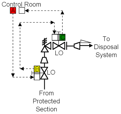
Normal operation :
i) Inlet and outlet block valves are in OPEN position
ii) Master Key A in cabinet inside control room
iii) Key B and C are located at inlet and outlet valve respectively.
PSV removal operation :
i) Collect key "A" from the control room.
ii) Insert key "A" in to the lock of Inlet block valve and close valve. Once valve in completely close position, key "B" can be released.
iii) Transfer and insert key "B" to lock of Outlet block valve and close valve.
iv) Release key "C" and return to control room to signify complete operation.
PSV re-installation operation :
i) Collect key "C" from the control room.
ii) Insert key "C" in to the lock of Outlet block valve and open valve. Once valve in completely open position, key "B" can be released.
iii) Transfer and insert key "B" to lock of Inlet block valve open valve.
iv) Release key "A" and return to control room to signify complete operation.
Dual PSVs arrangement
Following image is valve arrangement and typical key trapped lock for a Dual PSVs installation.
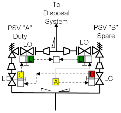
Normal operation :
i) Inlet and outlet block valves of DUTY PSV are in OPEN position
ii) Inlet block valve of SPARE PSV are in CLOSE position
iii) Outlet block valve of SPARE PSV are in OPEN position
iv) Master Key A in cabinet inside control room
iii) Key B, C, D are located at inlet and outlet valve respectively.
DUTY PSV removal operation :
i) Collect key "A" from the control room.
ii) Insert key "A" in to the lock of SPARE PSV Inlet block valve and open valve. Once valve in completely open position, key "B" can be released.
iii) Transfer and insert key "B" to lock of DUTY PSV Inlet block valve and close valve. Once valve in completely close position, key "C" can be released.
iv) Transfer and insert key "C" to lock of DUTY PSV Outlet block valve and close valve. Once valve in completely close position, key "D" can be released.
v) Release key "D" and return to control room to signify complete operation.
DUTY PSV re-installation operation :
i) Collect key "D" from the control room.
ii) Insert key "D" in to the lock of DUTY PSV Outlet block valve and open valve. Once valve in completely open position, key "C" can be released.
iii) Transfer and insert key "C" to lock of DUTY PSV Inlet block valve and open valve. Once valve in completely open position, key "B" can be released.
iv) Transfer and insert key "B" to lock of SPARE PSV Inlet block valve and close valve. Once valve in completely close position, key "A" can be released.
v) Release key "A" and return to control room to signify complete operation.
SPARE PSV removal operation :
i) Collect key "A" from the control room.
ii) Insert key "A" in to the lock of SPARE PSV Outlet block valve and close valve. Once valve in completely close position, key "D" can be released.
iii) Release key "D" and return to control room to signify complete operation.
SPARE PSV re-installation operation :
i) Collect key "D" from the control room.
ii) Insert key "D" in to the lock of SPARE PSV Outlet block valve and open valve. Once valve in completely open position, key "A" can be released.
iii) Release key "A" and return to control room to signify complete operation.
Related Posts
- Locked / Car-Sealed CLOSE PSV Inlet Isolation Valve ?
- Isolation Valve Position when Spare PSV present
- Concerns & Recommendations on PSV INLET line
- Concerns & Recommendations of PSV Discharge Tail pipe
- How CSO and CSC helps ?
- Locked Valve Increases Security, Reliability & Integrity
Labels: Overpressure Protection, Pressure Relief Device
Display problem ? Click HERE
In earlier discussion on "Another descrepancy found in API Std 521Jan 2007", the question is related to inclusion of specific heat ratio (k). This post is the follow-up and below presented the detail discussion and derivation of Mach no and critical pressure.
Recommended :
Subscribe FREE - Processing Magazine

One of the important assumption taken by API is consider ISOTHERMAL flow for Mach number, Critical pressure and pressure drop calculation. This concept is important as it affect the inclusion or exclusion of k in the formula. API consideration of ISOTHERMAL flow is reasonable as the fluid discharge to flare or vent network, the network is rather large and long and it possibly has sufficient time for heat transfer from metal or ambient. ISOTHERMAL flow is best suit for long pipeline modeling.
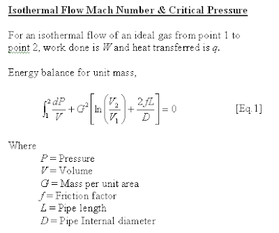
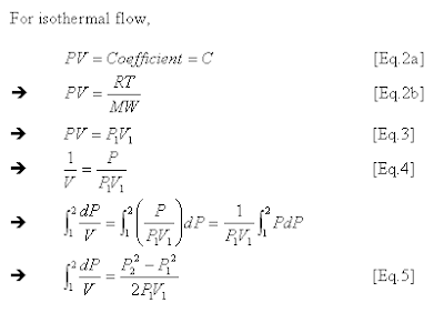
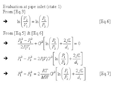
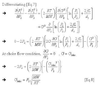

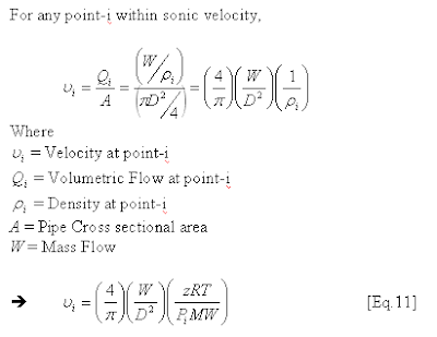
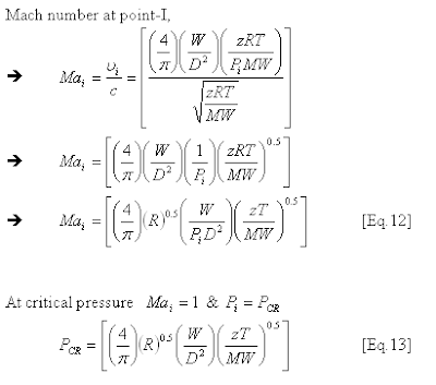
Above has shown that the by considering isothermal flow, the k factor should be omitted from the Mach number and critical pressure calculation.
Related Topics
Recommended :
Subscribe FREE - Processing Magazine
One of the important assumption taken by API is consider ISOTHERMAL flow for Mach number, Critical pressure and pressure drop calculation. This concept is important as it affect the inclusion or exclusion of k in the formula. API consideration of ISOTHERMAL flow is reasonable as the fluid discharge to flare or vent network, the network is rather large and long and it possibly has sufficient time for heat transfer from metal or ambient. ISOTHERMAL flow is best suit for long pipeline modeling.
Above has shown that the by considering isothermal flow, the k factor should be omitted from the Mach number and critical pressure calculation.
Related Topics
Labels: Flare, Fluid Flow
Saturday, September 27, 2008
Display problem ? Click HERE
In oil and gas production, formation water and condensed water present in oil and gas. These water cause hydrate formation in offshore transfer pipeline, severe slugging, corrosion, etc. They are contaminant shall be removed to meet the oil and gas specification. Water separated from oil and gas is normally contaminated with oil which can be in dispersed and diluted form. If the contaminated water is separated from a 2 phase or 3 phase separator , the oil contaminant level can be as high as 3000 ppmw. This level is far higher than the acceptable level of 30-40 ppmw. The contaminated water required further treatment.
Recommended :
Subscribe FREE - Processing Magazine
Contaminated water treatment are complicated. There are physical separation which includes solid-liquid separation, liquid-liquid separation, diluted component removal, etc as well as chemical treatment and biological treatment. In the physical separation, the normal technology used are hydrocyclone, corrugated plate pack unit, floatation unit, etc.
Similarly, the wastewater from daily usage i.e. wash water from kitchen is contaminated with oil. The oil and water may be separated with above mentioned unit. Following video clips presented a basic plate pack unit which separated oil from water before the water is discharged to public drainage. The separation principle is basically promote oil droplet coalescence in plate pack follow by gravity separation. The oil level in treated water can reach 20 ppmw level and possibly discharge directly to public drainage network (subject to local rules). The separated oil can be collected and storage in a storage tank and ready to be pumped to waste treatment plant for extraction.
Oil water separation process (video clip)
Oil water pre-module (video clip)
Oil water separation box (video clip)
Related Topic
Recommended :
Subscribe FREE - Processing Magazine
Contaminated water treatment are complicated. There are physical separation which includes solid-liquid separation, liquid-liquid separation, diluted component removal, etc as well as chemical treatment and biological treatment. In the physical separation, the normal technology used are hydrocyclone, corrugated plate pack unit, floatation unit, etc.Similarly, the wastewater from daily usage i.e. wash water from kitchen is contaminated with oil. The oil and water may be separated with above mentioned unit. Following video clips presented a basic plate pack unit which separated oil from water before the water is discharged to public drainage. The separation principle is basically promote oil droplet coalescence in plate pack follow by gravity separation. The oil level in treated water can reach 20 ppmw level and possibly discharge directly to public drainage network (subject to local rules). The separated oil can be collected and storage in a storage tank and ready to be pumped to waste treatment plant for extraction.
Oil water separation process (video clip)
Oil water pre-module (video clip)
Oil water separation box (video clip)
Related Topic
- Properly Simulate a Separator with Demister in HYSYS
- Factors you shall Consider for Separator with Boot
- Slugging & Slugcatcher
- Quick Understanding & Estimation of Mist Eliminator in Gas-Liquid Separator
- KnitMesh...Good Articles on Mist eliminator still available FREE...
- ACS - Design manual for Mist Eliminators, Trays, Packing, Internals...All in distillation columns
Labels: Separation, Separator
Thursday, September 25, 2008
Display problem ? Click HERE
Handbook of Chemical Hazard Analysis Procedures has objectives to expand Technical Guidance on Hazards Analyzes document by including information for explosive, flammable, reactive and otherwise dangerous chemicals. It also aimed to focus on a specifics initial list of acutely toxic chemicals (referred to as Extremely Hazardous Substances) due to their high inhalation toxicity when airborne.
Recommended :
- Subscribe FREE - Chemical Engineering
- Tips on Succession in FREE Subscription

This handbook provides methods to investigate local hazards in greater detail than permitted by earlier guidance, results of calculations using air dispersion models may differ. Continuous evaluation of types of models and others to determine the degree of Impact on calculations concerning the consequences of a chemical release.
Beyond providing additional methodologies for assessing the potential impact of hazardous material releases, thss handbook also expands the three-step hazards analysis approach which includes hazard identification, vulnerability analysis, and risk analysis.
If you are plant manager or engineers greatly dealing with a lot of chemicals, this would be a great handbook for you.
Click here to read this handbook. You may also download this handbook.
Related Posts
- An Introduction to Oil & Gas Production...
- 3 Most Important & FREE Magazines That I Read...
- Understand Boiler Efficiency
- Non - Technical Quick References for a Chemical & Process Engineers
- Instrumentation and Formulae & Conversion...
- R&D engineer, Academician and Student...Don't miss this !
- FREE E-book........A Heat Tranfer Textbook
- WOLVERINE - Offer FREE Heat Transfer Engineering Databook...
- Workbook for Chemical Reactor Relief System Sizing
- A must have book...Emergency Relief System Design Using DIERS Technology
Wednesday, September 24, 2008
Display problem ? Click HERE
Control valve has been widely used in Chemical & Process Plant for material feeding control and operating condition control. Today control valve technology is high in reliability and availability and long life span. It is a very mature technology. There are many handbooks and articles presented in earlier post "Useful Documents Related to Control Valves" and they are available for download.
 Besides theory and practical knowledge in articles, there are still many frequently asked questions related to control valve. Following is a list of frequently asked question (FAQ) related to control valve. It is pretty useful especially to young engineer.
Recommended :
Besides theory and practical knowledge in articles, there are still many frequently asked questions related to control valve. Following is a list of frequently asked question (FAQ) related to control valve. It is pretty useful especially to young engineer.The question includes :
Related Topic
- What is CV ?
- What is the difference between actual, standard and normal flow rates for gases ?
- What is Cavitation ?
- What is flashing ?
- What is choked flow ?
- How can cavitation damage be contained ?
- How can flashing damage be contained ?
- Is the velocity of a fluid in a control valve critical ?
- What is the difference between a liquid, a vapour and a gas ?
- What is a desuperheater and how does it differ from an attemporator ?
- Why do different control valves have different characteristics ?
- Definition of linear and equal percent characteristic ?
- What is the difference between installed and inherent characteristics ?
- Why are control valves sometimes very noisy ?
- Can two control valves be used in series in high pressure drop applications ?
- Can two control valves be used in parallel to handle high turndown applications ?
- What is the difference between rangeability and turndown ?
- What process data is required to size a control valve ?
- What is incipient cavitation?
- What is the difference between a diffuser plate and a choke ?
- What is a field reversible actuator ?
- Will separable flanged valves seal in a pipeline ?
- What is the trim in a control valve ?
- What is meant by Critical Pressure and Critical Temperature ?
- Is flow through a control valve turbulent or laminar ?
- What is vapour pressure ?
- Specific Gravity is the ratio of the density of a liquid to the density of water – What is Specific Gravity of a Gas ?
- What is meant by Cryogenic ?
- What materials can be used for Oxygen Service ?
- Why do Oxygen valves require degreasing ?
- Are safety valves, regulators and isolating valves all examples of control valves ?
- Why do some control valve actuators have a small internal fail action spring and some are external and larger ?
- Why is live loading sometimes offered on valves ?
- Why is reduced trim required in control valves ?
- How is the characteristic determined in a globe valve ?
- What effect does the positioner cam have on the valve characteristic ?
- Why is Energy dissipation an important factor in control valve selection?
Related Topic
- Useful Documents Related to Control Valve
- FREE & Reliable Control Valve Sizing Software
- Understand Droop Effect in Self-regulated Control Valve
- WELKER Jet Contorl Valve Handbook
- How to apply valve equation in HYSYS Depressuring ?
- Useful Documents Related to Pressure Relief Valve (PRV) - Part 1
- 12 Features required for Shutdown Valve (SDV)
Labels: Control valve
Tuesday, September 23, 2008
Display problem ? Click HERE
Recommended :
- Subscribe FREE - Chemical Engineering
- Tips on Succession in FREE Subscription
Locked / Car Sealed Close close (LC / CSC) pressure relief valve (PSV) isolation valve ???
For those who follow the earlier discussion "Isolation Valve Position when Spare PSV present", you may have aware of the reasoning why SPARE PSV is recommended to be in CLOSE position. Besides, API RP 520 part 2, section 6.3.3 recommendation is inline with above discussion. This post is a follow-up discussion on the same subject, however it extends to the requirement of Locking or Car-Sealed Closed an inlet isolation valve for a SPARE PSV.
One point shall be clear up-front is that the main subject here is the locked or car-sealed close a SPARE PSV. For DUTY PSVs, all inlet and outlet isolation valves SHALL be in OPEN position to ensure clear relief flow path.

A duty PSV inlet isolation valve shall be locked or car-sealed to avoid inadvertently closure of inlet isolation valve. However, the locking or car-sealing of spare PSV inlet isolation valve which should be in close position is arguable. Some engineers argued that the inlet should not be locked or car-sealed. It is quicker to unlocked a LC or unsealed a CSC isolation valve when it is required or on demand during emergency.
Above argument could be right. However, inadvertent opening followed by overpressure relieving scenario could lead to potential catastrophe. As explained in "Isolation Valve Position when Spare PSV present", PSV chattering is likely to occur when spare PSV is relieving simultaneously with duty PSV. PSV chattering not only lead to seat damage, severe vibration lead to mechanical damage (which is difficult to be studied) could occur due to PSV chattering. The consequence of mechanical damage may lead to catastrophe.
"A recently gas leak occurred on an offshore gas Central Processing Facility as a consequence of the failure of the bellows in balanced bellows Pressure Safety Valves (PSVs). All three PSVs in service on the inlet Slug Catcher from a remote field were simultaneously affected by the failure of their bellows due to chattering during relief of pressure from the vessel. Each of the three ¾ inch PSV bonnet vents exhausted directly to atmosphere and the incident resulted in approximately 235kg of gas being released in the process area, an Emergency Shutdown (ESD), pressure blowdown and a General Platform Alarm."
Above is one incident reported in one the offshore platform.
PSV Chattering lead to bellow damage and gas leak in to atmosphere via bonnet vent. This gas leak would potential form gas cloud and lead to vapor cloud explosion. So do not under-estimate PSV chattering.
Besides the catastrophe, disc and seat damage during chattering cause improper closure and permanent continuous fluid leaks. Plant is forced to shutdown and depressurise. Inventory loss, cost for PSV repair or replacement of PSV and production loss during shutdown period would be much much higher than a simple locking or car-sealing device on a spare PSV inlet isolation valve.
Inadvertent opening followed by overpressure relieving scenario... Is this double jeopardy ?
Operator inadvertently open the spare PSV inlet isolation valve and overpressure of the system lead to relieving are two non-related event. In simple term, open spare PSV inlet isolation valve event will NOT cause the happening of overpressure of the system event. They are non-related. However, they are possibly occur in sequence. Morning shift operator may open the spare PSV inlet isolation valve and leave it open. Nothing happen during morning shift as no overpressure event occur. During night shift, controller failure of outlet pressure control loop lead to blocked outlet event (control valve close position) and overpressure occur. Both duty and spare PSV open and chattering occur. Thus, both events are non-related but in sequence.
Related Posts
Related Posts
Labels: Overpressure Protection, Pressure Relief Device
Monday, September 22, 2008
Display problem ? Click HERE
A pressure containment equipment shall be pressure tested before it is authorized to be in real world service. Once the equipment is pressure tested, the equipment integrity is preserved. However, failure in testing the equipment would creates safety concerns to all level of personnel.
Recommended :Subscribe FREE - Processing Magazine
Testing Medium Selection
Pressure test is normally carried out using air (pneumatic test) and water (hydrostatic test). In some event for some equipment i.e reactor, inert gases (e.g., nitrogen) or liquids are used as air or water would possibly create concerns i.e. corrosion, cracking, etc to the equipment. Proper selection of testing medium is one of the critical task which shall involve process and chemical designer. Several aspect shall be checked for the selection of testing medium :
i) Corrosion cracking i.e. Chloride Stress Corrosion Cracking (CSCC) in stainless steel vessel due to present of Chloride in water
ii) Metal embrittlement i.e. Mercury embrittlement in aluminum heat exchanger due to present of mercury in air
iii) Present of low pocket in equipment will trap water if water or wet air is used. Water stay in the equipment promote corrosion
iv) Equipment handling vapor or gas, preferentially pressure test with air and vice versa
v) Selection of testing medium could also subject to the pre-commissioning activities. For example, large amount of water used for slugcatcher hydrostatic testing may be transferred to other equipment for hydrostatic testing or water circulation test.
vi) Mixture of air and water sometime is employed to save cost.
The great advantage of using air or water compare to other fluid are easy handling, cheap testing cost, less / no corrosion and cracking to many type of material.
Pressure Testing Failure
As many newly fabricated equipment subject to pressure test, equipment failure during pressure test may occur and could lead to catastrophe. Following are some failure incidents during process preparation and implementation of pressure test.
i) Vessel cracked during hydrostatic test.
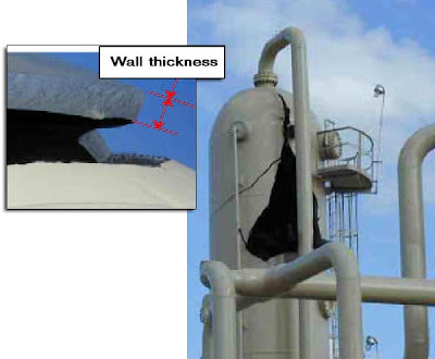
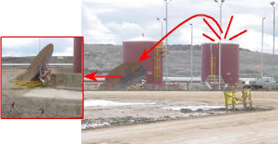
ii) Overpressure during preparation of hydrostatic. Tank top blew off due to high water filling (using hydrant) rate with low capacity relief valve.
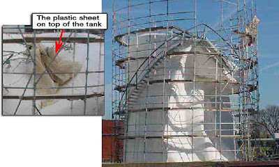
iii) Tank collapsed during emptying of water after hydrostatic test. Plastic coversheet block air inlet and create vacuum. Read more Vacuum
i) Corrosion cracking i.e. Chloride Stress Corrosion Cracking (CSCC) in stainless steel vessel due to present of Chloride in water
ii) Metal embrittlement i.e. Mercury embrittlement in aluminum heat exchanger due to present of mercury in air
iii) Present of low pocket in equipment will trap water if water or wet air is used. Water stay in the equipment promote corrosion
iv) Equipment handling vapor or gas, preferentially pressure test with air and vice versa
v) Selection of testing medium could also subject to the pre-commissioning activities. For example, large amount of water used for slugcatcher hydrostatic testing may be transferred to other equipment for hydrostatic testing or water circulation test.
vi) Mixture of air and water sometime is employed to save cost.
The great advantage of using air or water compare to other fluid are easy handling, cheap testing cost, less / no corrosion and cracking to many type of material.
Pressure Testing Failure
As many newly fabricated equipment subject to pressure test, equipment failure during pressure test may occur and could lead to catastrophe. Following are some failure incidents during process preparation and implementation of pressure test.
i) Vessel cracked during hydrostatic test.
ii) Overpressure during preparation of hydrostatic. Tank top blew off due to high water filling (using hydrant) rate with low capacity relief valve.
iii) Tank collapsed during emptying of water after hydrostatic test. Plastic coversheet block air inlet and create vacuum. Read more Vacuum
iv) Sphere tank collapse during water filling due to severe corrosion on the support.
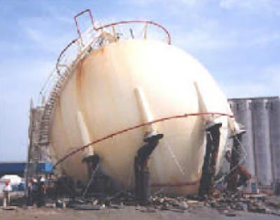
* all images are courtesy of www.oilandgasconstruction.com
Some Guidelines
Thus, do not underestimate the safety issue during pressure testing. Any equipment could failed if improper handling is used. Several guidelines on pressure testing are listed :
Related Post
* all images are courtesy of www.oilandgasconstruction.com
Some Guidelines
Thus, do not underestimate the safety issue during pressure testing. Any equipment could failed if improper handling is used. Several guidelines on pressure testing are listed :
- Check testing medium compatibility
- Check water and /or air supply pressure is sufficient
- Ensure venting capacity is sufficient for filling rate
- Ensure the vent is large enough to avoid vacuum during water emptying after hydrostatic test if the tank or vessel is not designed to full vacuum
- Check vessel support and foundation is fit for liquid or water testing during preparation especially testing for used equipment. Corrosion is one of major concern
- Present of internal i.e. mist mesh, bubble cap, valve tray, etc could create restriction and potentially lead to partial vacuum. Drain water in control manner.
- Keep personnel away
Related Post
- Vacuum Hazard - Another Catastrophic Factor...
- 4-steps Approach to Combat Vacuum Hazard
- Dust Explosion Basic & Protection
- Blast rocks Texas oil refinery
- Design fault in Hydrogen Attack of Residue Hydrodesulfurrization
Labels: Overpressure Protection
Sunday, September 21, 2008
Display problem ? Click HERE
Recommended :
- Tips on Succession in FREE Subscription
- Subscribe FREE - Hydrocarbon Engineering
Isolation valves are provided upstream and downstream of the PSV to facilitate PSV isolation for inspection and maintenance purpose. There are several points related to this isolation valve and other recommendations in "Concerns & Recommendations on PSV INLET line" and "Few Concerns & Recommendations of PSV Discharge Tail pipe". These isolation valves are normally either Car Seal Open (CSO) or Locked Open (LO) to avoid operator inadvertently close these valves, unless required by safety analysis i.e HAZOP. Read more about Car Seal and Lock system in "How CSO and CSC helps ?" and "Locked Valve Increases Security, Reliability & Integrity".
Increases demand on plant availability and operability lead to sparing of Pressure Relief Valve (PSV). Nevertheless, there is different philosophy on the isolation valve position in the event present of spare PSV. Let see the following image.
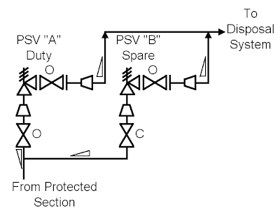
Isolation Valve Position
- Duty PSV Inlet & Outlet
The duty PSV inlet and outlet PSV are in OPEN position to ensure 100% flow path when it is on demand.
- Spare PSV Inlet
The spare PSV inlet isolation valve should be in CLOSE position to minimize possibility and occurrence of PSV passing due to damaged and imperfect seat during normal operation and PSV chattering in case the overpressure scenario occurred.
- Spare PSV Outlet
The spare PSV outlet isolation valve should be in OPEN position to avoid the situation where pressure built-up, condensation and corrosion of the section between spare PSV outlet and isolation valve in case of valves passing (inlet isolation and PSV passing.
How PSV chattering occur in case both Valves are in OPEN position ?
There are several factors lead to occurrence of PSV chattering.
Factor (i) Excess Relief Area
- For a system protected with 2 x PSVs with identical set pressure as shown in above images, if both PSVs inlet are in OPEN position and in the event pressure built-up to set pressure, both PSVs will pop open. 200% of opening area serving 100% relief flowrate, this would evacuate the internal contents sharply, internal pressure decreases quickly and reduce overpressure range (percentage overpressure above set point reduce). Both PSVs will quick move into PSVs reseating cycle. As flow into 2 x PSVs, half of the relief flow (assumed perfect distribution) will goes into 1 x PSV, during reseating cycle, reduced flow will cause less force on the disc and reduce blowdown (as both PSV's blowdown were set for 100% flow). The blowdown reduction could be high and cause blowdown less than 7% as normally requested by API. Reduced overpressure and blowdown would cause PSV chatter and damage PSV disc and seat.
Factor (ii) Imperfect flow distribution
Apart from reduce flow 100% to 50% each PSV, different inlet pipe routing, different fouling or corrosion level in the inlet piping would lead to mal-distribution of flow into each PSV. This would cause even less flow (less than 50% ) into one of the PSV. Imperfect flow distribution on the inlet line would made the overpressure and blowdown even lower and promote PSV chattering
Factor (iii) Non-equal spring force and friction
Non-equal spring force, friction , etc between both PSVs in real world operation possibly resulted 1 x PSV open slightly faster than the other. This subsequently lead to both PSV's spring seeing different pressure on disc. One PSV might be on opening cycle and the other on closing cycle. The PSV on opening cycle will experience less force and tends to close while the PSV on closing cycle will experience more force and tends to open more. Until a point, both PSVs opening - closing cycle will exchange. Both PSV will fighting each and other. This is another type of PSV chattering phenomenon. Again, mal-distribution of flow would promote this phenomenon.
PSV Chattering
PSV Chatter is rapid reciprocating motion of the disc where the disc contacts with the seat in cyclic motion. Chatter is destructive where it repetitive and rapid reciprocating disc knock on the valve seat may cause
i) damage to the disc & valve seat lead to leakage and passing
ii) damage to bellow lead to gas leak via bonnet vent
iii) damage to the PRV itself and interconnecting piping through vibration
iv) severe noise level
Read more in "PSV Chaterring is Destructive...The ways to Prevent..."
Besides above discussion, read may also encourage refer to API RP 520 part 2 (2000 rev), section 6.3.3 recommendation.
Related Posts
- Concerns & Recommendations on PSV INLET line
- Concerns & Recommendations of PSV Discharge Tail pipe
- How CSO and CSC helps ?
- Locked Valve Increases Security, Reliability & Integrity
- Relate PSV Relieving Flow to Stamped Capacity
- Thermal Relief of Non-Flashing Liquid in Pipe
- Simple Flow Chart to Determine Requirement of Thermal Relief
Labels: Overpressure Protection, Pressure Relief Device
Friday, September 19, 2008
Display problem ? Click HERE
Earlier post "Two Most Important Articles for Heuristic in Chemical Engineering" has introduced to you two articles tabulated the rules of thumbs and heuristic in chemical engineering. In Oct 2006, Mr. Alejandro Anaya Durand from National Autonomous University of Mexico has published another interesting article related to rule of thumbs named "Heuristics Rules for Process Equipment" via chemical engineering. The rule of thumbs covers several important equipments :
Always remember...
Never believe that rule of thumb is a tool for all purpose. Detail and conventional design approach shall be employed for a correct and proper works and product. Nevertheless, the beauty of rule of thumb is it contain some simple, hard-earn and workable approaches and guidelines that helps you to shorten your trial-n-error cycles and save your time. Use it to get a rough idea of your product to-be and use detail approach for proper design.
Problem getting the article, may drop me a note...
Related Post
- Fluid handling
- Conveying of particulate solids
- Cooling towers
- Heat exchangers; refrigeration
- Evaporators
- Drums
- Reactors
- Storage tanks
- Distillation and gas absorption
- Liquid-liquid extraction
- Crystallization from solution
- Filtration
- Drying of solids
- Size reduction
- Mixing and agitation
- Agglomeration
Always remember...
Never believe that rule of thumb is a tool for all purpose. Detail and conventional design approach shall be employed for a correct and proper works and product. Nevertheless, the beauty of rule of thumb is it contain some simple, hard-earn and workable approaches and guidelines that helps you to shorten your trial-n-error cycles and save your time. Use it to get a rough idea of your product to-be and use detail approach for proper design.
Problem getting the article, may drop me a note...
Related Post
- 3 Most Important & FREE Magazines That I Read...
- Non - Technical Quick References for a Chemical & Process Engineers
- R&D engineer, Academician and Student...Don't miss this !
- More You Share More You Learn
- Knowledge is Own by Everyone but Not Someone
- Tips on Succession in FREE Subscription
- FREE Chemistry Periodic Table Software
Labels: E-Doc, Education, Learning
Thursday, September 18, 2008
Display problem ? Click HERE
There are quite a number of posts are circulated around the Shell & Tube Heat Exchanger tube rupture :
- Criteria for Requirement of Pressure Relief Device for Tube Rupture
- Complicated Tube Rupture Scenario... Nightmare in Sizing a PRD
- Two-third (2/3) rule or Ten-thirteen (10/13) rule ?
- Tube Rupture : Pressure Relief Valve (PSV) or Rupture Disk (RD) ?
- Practical Measures to Eliminate or Avoid HX Tube Rupture Scenarios
- How to consider Area for Relieving flow in Plate Heat Exchanger Internal Failure
- Another Way to Manage Liquid Disposal Cause by Tube Rupture
Surge Pressure more than MAWP of LPS even NOT blocked-in...
Whenever a tube rupture occurred, compressible fluid (vapor) in High Pressure Side (HPS) flowing into Low Pressure Side (LPS) with incompressible fluid (water), there is momentary surge. This momentary surge would possibly lead to instantaneous peak pressure which possibly exceeded the Maximum Allowable Working Pressure (MAWP) of the Heat exchanger LPS. One shall noted that the word "possibly" but not always the case. It is very difficult to quantify this surge pressure as it subject to where & how tube rupture occurred, fluid impinging the shell wall, resonance occur, etc. A very special phenomenon that you may not believe, surge pressure is possible exceed the MAWP of LPS even though the LPS side is not blocked in especially those system with rotating equipment, check valve, control valve, etc. Of course, blocked in condition would seriously increase the possibility of surge pressure exceeded MAWP. Thus, a dynamic surge simulation & analysis may provide the answer.
Recommended :
- Subscribe FREE - Chemical Engineering
- Tips on Succession in FREE Subscription
Qualification for Not Having PRD for Tube Rupture...
Many designers still arguing about 2/3 rules and 10/13 rules. The post "Two-third (2/3) rule or Ten-thirteen (10/13) rule ?" would probably provide some idea. Whenever above rules is applied, one shall used the correct terms in rule application. Read more in "Criteria for Requirement of Pressure Relief Device for Tube Rupture". Regardless of which rules is used for a specific case, the principle still same :
- Corrected Test pressure of low pressure side MORE than Design pressure of high pressure side
Does it stop at the first valve at the inlet and outlet of the heat exchanger ?
Does it extended to entire network after the first valve ?
Recommendations
First point : The LPS design pressure shall be at least upto the first isolation valve at the inlet and outlet of the heat exchanger.
Second point : The LPS design pressure will be extended to equipment or device which possibly block-in. For example manual block downstream which is normally open, filter, solid bed, etc. All these items, possible partial or total blockage.
Third point : In the event, there is no equipment or device possibly block-in and overpressure the piping, the LPS design pressure may not need to be extended to the downstream piping. However, another phenomenon shall be addressed and checked to ensure the LPS design need not be extended. Fluid from HPS side will flow into LPS, fluid in HPS (compressible) may expand. Apart large flow passing through the ruptured tube. Both expansion and large flow discharge into LPS will get into the downstream piping network and release some way downstream via PRD. A high back pressure may occur at the location of the ruptured tube heat exchanger. This back pressure might exceed the MAWP of the piping. Thus, one shall calculate the back pressure along the relief path and ensure pressure at any point in the piping is below the MAWP of piping.
Some engineers may consider short term overpressure excursion rule as allowed in ASME code to quality non-credible tube rupture scenario. The only recommendation that can be advised here is this rule may be used with care.
Related Topic
- Criteria for Requirement of Pressure Relief Device for Tube Rupture
- Complicated Tube Rupture Scenario... Nightmare in Sizing a PRD
- Two-third (2/3) rule or Ten-thirteen (10/13) rule ?
- Tube Rupture : Pressure Relief Valve (PSV) or Rupture Disk (RD) ?
- Practical Measures to Eliminate or Avoid HX Tube Rupture Scenarios
- How to consider Area for Relieving flow in Plate Heat Exchanger Internal Failure
- Another Way to Manage Liquid Disposal Cause by Tube Rupture
Labels: Overpressure Protection, Pressure Relief Device
Tuesday, September 16, 2008
Display problem ? Click HERE
If you have worked on P&ID, you probably have seen an isolation valve with a globe valve across a pressure relief valve (PRV). See below image.
What is this arrangement and what the purpose of installing them ?
Recommended :
- Subscribe FREE - Chemical Engineering
- Tips on Succession in FREE Subscription
Many engineer may have aware of this purpose of this line. This arrangement is a manual blowdown line. It is normally used system inerting during start-up and system purging during shutdown maintenance. As the source of the inventory is same as PRV i.e. vessel and the discharge location is same i.e. flare, thus it is generally drawn in P&ID as such. Similarly it also being arranged in parallel with PRV in actual installation.
Some engineers may understand the main purpose of this arrangement but somehow mis-called it as PRV bypass. It is pretty same as the control valve (CV) bypass arrangement. In reality operator can operate the CV bypass and throttle the flow manually by the bypass globe valve while operator take out the control valve for maintenance purpose. However, operator is absolute not allowed to bypass the PRV. When designer write the operating manual, the correct terms shall be used to avoid any misunderstanding. This could be a minor error however sometime it is important.
Some recommended features associate with this arrangement are as follow :
Although above manual blowdown line is pretty simple, there are still features associate with it. Above is non-exhaustive list of features. If you find any special conditions, welcome your advice and comments.
Related Post
- Subscribe FREE - Chemical Engineering
- Tips on Succession in FREE Subscription
Many engineer may have aware of this purpose of this line. This arrangement is a manual blowdown line. It is normally used system inerting during start-up and system purging during shutdown maintenance. As the source of the inventory is same as PRV i.e. vessel and the discharge location is same i.e. flare, thus it is generally drawn in P&ID as such. Similarly it also being arranged in parallel with PRV in actual installation.
Some engineers may understand the main purpose of this arrangement but somehow mis-called it as PRV bypass. It is pretty same as the control valve (CV) bypass arrangement. In reality operator can operate the CV bypass and throttle the flow manually by the bypass globe valve while operator take out the control valve for maintenance purpose. However, operator is absolute not allowed to bypass the PRV. When designer write the operating manual, the correct terms shall be used to avoid any misunderstanding. This could be a minor error however sometime it is important.
Some recommended features associate with this arrangement are as follow :
- The isolation valve and globe valve shall be arranged such that no low pocket present as liquid possible present in low pocket promote corrosion
- These arrangement install at high point so that liquid is sloping away from them
- Maintain a distance i.e. 600mm between isolation valve and globe valve to avoid isolation valve stuck open during manual blowdown. See reasoning in "Why Restriction Orifice is some distance from Blowdown valve ?"
- The recommended size of the line and valve is 2". If size smaller then 2" is used, concern of severe vibration of small bore connection (SBC) shall be addressed.
- The short line downstream of globe valve to connection is recommended to design to MACH number lower than unity (1) i.e. 0.8 when the globe valve is fully open. This is to avoid operator inadvertently open the globe valve.
- The downstream piping shall be sufficiently thick to ensure it is failed on acoustically induced vibration.
- The isolation valve may be Normally Closed (NC). However, losing inventory due to inadvertently open of this blowdown valve is deem to be a concern, the isolation valve may be Car Sealed Close (CSC) or Locked Close (LC).
- Prior to any blowdown, the operator may leave the upstream system settle out. This allow the internal fluid temperature cooled to minimum possible ambient temperature. Manual blowdown after settled out would lead to very low temperature downstream of globe valve. Thus the low temperature during manual blowdown shall be studied to ensure the material will not failed on low temperature embrittlement.
- If the fluid is having high pour point, solidify or crystallize under minimum ambient temperature, etc, may consider insulating and/or heat trace the line.
Although above manual blowdown line is pretty simple, there are still features associate with it. Above is non-exhaustive list of features. If you find any special conditions, welcome your advice and comments.
Related Post
- A refresh to Process Engineer on few phenomenons in restriction orifice
- Bug in ASPENTECH HYSYS 2006 Dynamic Depressuring Fisher Valve model
- Controlled and Non-controlled Type Depressuring
- How to apply valve equation in HYSYS Depressuring ?
- Why Restriction Orifice is some distance from Blowdown valve ?
- Restrcition Orifice Used in Many Applications in Different Manners
- How to Resolve Issue with PSV Inlet Line Loss Exceeded 3% of Set pressure
- Few Concerns & Recommendations of PSV Discharge Tail pipe
- Few Concerns & Recommendations on PSV INLET line
Labels: Depressurization, Overpressure Protection, Pressure Relief Device
Sunday, September 14, 2008
Display problem ? Click HERE
Subscribes to FREE Hydrocarbon Processing
 A couple of days ago, a young engineer drop us a note and request us to advise the route to be Professional engineer in India after he has read "Practicing Engineering & Route To Professional Engineer in MALAYSIA". We have tried our best to locate the information and hoping these informations will provide some guidance for him as well as other engineers practicing in India.
The Institution of Engineers (India), IEI, the largest multi-disciplinary professional institution of engineers, had been certifying Professional Engineers (PEs) for over a decade. With increasing globalization and trade in services, enabling free movement of professionals across the world, the necessity of engineers acquiring international level certification has become inescapable. The Institution of Engineers (India), responding to the requirement and in service of engineering profession, has modified systems and procedures of "Certification of Professional Engineers" in line with international norms and has obtained provisional membership of the Engineers Mobility Forum (EMF). The Professional Engineers so certified to the international level and placed on International Register after due process, would be eligible to practice their profession internationally without additional scrutiny or certification beyond what is applicable to domestic engineers in the receiving countries.
To reach The Institution of Engineers (India) website... Click here
To know more on membership... Click here
To know how to become a Professional Engineer (PE) in India... Click here
To obtain Guideline to applicant to PE in India... Click here
To download Application form... Click here
To read more on Assessment Examination... Clck here
To read more about Code of Ethic for PE... Click here
While accessing the IEI, several articles found to be interesting :
CHEMCIAL
- Extraction of Copper (II) and Nickel (II) from Wastewater by Emulsion Liquid Membranes
- Bio-leaching of Zinc Sulphide (ZnS) Ore using Thiobacillus ferrooxidans
- Artificial Neural Network-based Prediction of Bed Expansion Ratio in Gas-Solid Fluidized Beds with Disk and Blade Promoters
- Relationship among the Rate Constants in Sedimentation of Haematite Slurry in Water
- Sedimentation of Haematite Water Slurries
- Recovery of Titanium from Coal Ash using Immobilized Liquid Membranes
- Use of Artificial Neural Networks for Prediction of Cell Mass and Ethanol Concentration in Batch Fermentation using Saccharomyces cerevisiae Yeast
- De-inking of Indian Newspaper by Agglomerate Floatation
- Sand Consolidation Experience in the Niger Delta
- Natural Convective Heat Transfer in Helical Coiled Heat Exchanger
- Correlations to Predict Permeate Flux and Rejection in Ultra-filtration Based on Dimensional Analysis
- A Combined Linear and Hyperbolic Equation to Fit Data on Sedimentation of Haematite Slurry in Water
- End of Small Volume High Value Myth in Biotechnology -- Process Design for a Mega-plant Producing c - Interferon for Mega Profit
- Heat Transfer Analysis of Free Convection of a Non-Newtonian Power Law Fluid over a Vertical Plate with Constant Heat Flux
- Relationship between Rate Constants in Sedimentation of Coal Slurry in Water
- Hydrodynamic Studies on Gas-Liquid Down-flow Bubble Column with Non-Newtonian Liquids
- Studies of Degradation of Waste Polyethylene Terephthalate using Autoclave Technique
- Activated Sludge Bulking : A Review of Causes and Control Strategies
- Design of Cylinder Pre-stressed Concrete Pipeline
- Effect of Substrate Depth on Vermi-composting
- Modelling of Pollutant Transport in Ground Water
- Quality of Water Flowing through Tolly's Nullah within Kolkata Municipal Area
- Use of Clay-bed Liner for Retention of Chromium from Aqueous Media : A Laboratory Study
- Vehicular Pollution Modelling in India
- Water Quality and Flow Simulation in River Kali, India
Above informations were extracted from the official website of The Institution of Engineers (India), IEI. The information may have been changed or updated from time to time. It can used as reference but details shall be referred to The Institution of Engineers (India). See below :
For more information, contact :
The Secretary,
Board for Certification,
The Institution of Engineers (India),
8 Gokhale Road, Kolkata 700 020
[ Phones : +91-033-2223 3296 (direct) / +91-033-2223 8311, Extn. 237 (EPABX); Facsimile : +91-033-2223 8345; E-mail : ddg@ieindia.org
Apart, if you are one of the PE in India, you are welcome to provide more inputs in the comments section in order to promote Engineering Professionalism in general and in INDIA specifically...
Other Articles
- Practicing Engineering & Route To Professional Engineer in MALAYSIA
- Two Most Important Articles for Heuristic in Chemical Engineering
- 3 Most Important & FREE Magazines That I Read...
- Non - Technical Quick References for a Chemical & Process Engineers
- R&D engineer, Academician and Student...Don't miss this !
Friday, September 12, 2008
Display problem ? Click HERE
Recommended :
- Tips on Succession in FREE Subscription
- Subscribe FREE - Hydrocarbon Engineering
Isothermal flow equation is widely used to size Pressure Relief Valve (PRV) discharge piping and flare network all the way to flare tip. Generally sizing of PRV discharge or flare network piping can usually be simplified by starting at the system outlet i.e. flare tip, where the pressure i.e ATMOSPHERE is known , and working backward through the network till the PRV. The back pressure can affect performance of PRV as discussed in "Several Impact of Backpressure on Conventional PRV" and "How Back Pressure Affect Conventional PSV Set Pressure Subject to It Vent". From the outlet system, the calculations are performed in a stepwise manner for each pipe segment of constant diameter, backward through the network.
The isothermal flow equation based on inlet and outlet Mach number are as given in Equation (25) and (26) in API Std 521 - ISO 23251, Edition 5, Jan 2007, "Pressure-relieving and Depressuring Systems - Addendum-May2008". Figure 14 (see below) in this standard is a typical graphical representation of Equation (25) and it may be used to calculate the inlet pressure, p1, for a line segment of constant diameter where the outlet pressure is known.
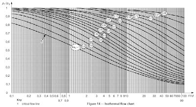
The vertical axis represented by (P1/P2) while the horizontal axis represented (f.l/d). From the definition, P1 is inlet absolute pressure while P2 is outlet absolute pressure. As P1 shall always larger than P2, thus P1/P2 shall always more than unity (1). However, looking at the vertical (P1/P2) axis, the value is from zero to one. This seen un-realistic.
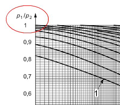
A back check on the previous revision (1997) and source paper, it was found that the vertical axis should be (P2/P1) instead of (P1/P2). The minor error will be reflected to API for verification.
Thanks to Sheiko to share this information with Chemical Process Technology.
- Tips on Succession in FREE Subscription
- Subscribe FREE - Hydrocarbon Engineering
Isothermal flow equation is widely used to size Pressure Relief Valve (PRV) discharge piping and flare network all the way to flare tip. Generally sizing of PRV discharge or flare network piping can usually be simplified by starting at the system outlet i.e. flare tip, where the pressure i.e ATMOSPHERE is known , and working backward through the network till the PRV. The back pressure can affect performance of PRV as discussed in "Several Impact of Backpressure on Conventional PRV" and "How Back Pressure Affect Conventional PSV Set Pressure Subject to It Vent". From the outlet system, the calculations are performed in a stepwise manner for each pipe segment of constant diameter, backward through the network.The isothermal flow equation based on inlet and outlet Mach number are as given in Equation (25) and (26) in API Std 521 - ISO 23251, Edition 5, Jan 2007, "Pressure-relieving and Depressuring Systems - Addendum-May2008". Figure 14 (see below) in this standard is a typical graphical representation of Equation (25) and it may be used to calculate the inlet pressure, p1, for a line segment of constant diameter where the outlet pressure is known.
The vertical axis represented by (P1/P2) while the horizontal axis represented (f.l/d). From the definition, P1 is inlet absolute pressure while P2 is outlet absolute pressure. As P1 shall always larger than P2, thus P1/P2 shall always more than unity (1). However, looking at the vertical (P1/P2) axis, the value is from zero to one. This seen un-realistic.
A back check on the previous revision (1997) and source paper, it was found that the vertical axis should be (P2/P1) instead of (P1/P2). The minor error will be reflected to API for verification.
Thanks to Sheiko to share this information with Chemical Process Technology.
Related Topics
Labels: Overpressure Protection, Pressure Relief Device
Thursday, September 11, 2008
Display Problem ? Click HERE
Recommended :
Subscribe FREE - Processing Magazine
Hydrocarbon condensate generated from fractionation unit and condensate stabilization unit will be stored in condensate tank before it is loaded into ship for export. The condensate storage tank is blanketed with inert gas i.e. Nitrogen to avoid moisture ingress and contaminated the condensate. Condensate storage tank in normally fixed roof tank and protected by Pressure Vacuum Relief Valve (PVRV) from overpressure and vacuum hazard. Concerning vacuum hazard and causes, read more in "Vacuum Hazard - Another Catastrophic Factor..." and some recommendations to minimize /avoid vacuum hazard in "4-steps Approach to Combat Vacuum Hazard".
In sizing a PVRV for tank, API Std 2000 Venting Atmospheric and Low Pressure Storage Tanks is used. In the standard, inbreathing rate due to thermal and pump-out and outbreathing due to pump-in, thermal and fire can be referred. Nevertheless, the Outflow and Inflow rate are presented in air equivalent flow at Standard condition (14.7 psia & 60 degF) for English unit and Normal condition (1.014 bara & 0 degC) for SI unit. There are some level of conversion required between actual vapor flow, standard vapor flow and air standard flow. Sometime it creates some confusion to engineer.
Following are some equations for the conversion and pretty useful for young engineer for verification purpose.
(A) Convert Air Volumetric Flow (@ Std) to Vapor Volumetric Flow (@ Std)
Vapor Volumetric Flow @ STD = Air Volumetric Flow @ STD × Vapor Temperature Correction Factor / Vapor Specific Gravity Correction Factor
[Eq.1]
QStd,Vap = QStd,Air × √[(TStd,Vap+460) ⁄ (TActual,Vap+460)] / √[MWVap / MWAir]
where
QStd,Vap = Vapor Volumetric Flow @ STD (SCFH)
QStd,Air = Air Volumetric Flow @ STD (SCFH)
TStd,Vap = Vapor Temperature @ STD = 60 degF
TActual,Vap = Actual Vapor Temperature (degF)
MWVap = Vapor Molecular Weight
MWAir = Air Molecular Weight (28.96)
(B) Convert Vapor Volumetric Flow (@ Std) to Vapor Volumetric Flow (@ Actual)
Vapor Volumetric Flow @ PT = Vapor Volumetric Flow @ STD × [Actual Temperature / Standard Temperature] × [Std Pressure / Actual Pressure ]
[Eq.2]
QActual,Vap = QStd,Vap × [(TActual,Vap+460) ⁄ (TStd,Vap+460)] × [PStd,Vap/PActual,Vap]
where
QActual,Vap = Actual Vapor Flow (SCF)
PStd,Vap = Vapor Pressure @ STD (14.7 psia)
PActual,Vap = Actual Vapor Pressure (psia)
Example 1 :
Nitrogen (MW=28) blanketing a tank. The calculated air flow @ std is 50,000 SCFH. The tank is at 1 psig and 68 degF when venting via PVRV occurred. Calculate the equivalent Nitrogen relief load at actual flow condition.
From [Eq.1]
QStd,N2 = QStd,Air × √[(TStd,N2+460) ⁄ (TActual,N2+460)] / √[MWN2 / MWAir]
QStd,N2 = 50000 × √[(60+460) ⁄ (68+460)] / √[28 / 28.96]
QStd,N2 = 50463.22 SCFH
From [Eq.2]
QActual,N2 = QStd,N2 × [(TActual,N2+460) ⁄ (TStd,N2+460)] × [PStd,N2/PActual,N2]
QActual,N2 = 50463.22 × [(68+460) ⁄ (60+460)] × [14.7/(14.7+1)]
QActual,N2 = 47975.91 CFH
Example 2 :
A tank feed from condensate stablizer. In case of gas blowby, flash vapor generated plus displaced vapor (MW = 35) is 60,000 CFH and tank is at 1.5 psig and 122 degF when venting via PVRV occurred. Calculate the equivalent Air flow at STD condition.
From [Eq.2]
QAct,Vap = QStd,Vap × [(TAct,Vap+460) ⁄ (TStd,Vap+460)] × [PStd,Vap/PAct,Vap]
QStd,Vap = QAct,Vap × [(TStd,Vap+460) ⁄ (TAct,Vap+460)] × [PAct,Vap/PStd,Vap]
QStd,Vap = 60000 × [(60+460) ⁄ (122+460)] × [(1.5+14.7)/14.7]
QStd,Vap = 59078.48 SCFH
From [Eq.1]
QStd,Vap = QStd,Air × √[(TStd,Vap+460) ⁄ (TActual,Vap+460)] / √[MWVap / MWAir]
QStd,Air = QStd,Vap × √[(TActual,Vap+460) ⁄ (TStd,Vap+460)] / √[MWAir / MWVap]
QStd,Air = 59078.48 × √[(122+460) ⁄ (60+460)] / √[28.96 / 35]
QStd,Air = 68710.62 SCFH
Concluding Remark
Above equations are pretty useful for conversion of air - vapor and actual-standard condition especially when you are dealing with tank relief sizing and PVRV verification.
Related Post
Subscribe FREE - Processing Magazine
Hydrocarbon condensate generated from fractionation unit and condensate stabilization unit will be stored in condensate tank before it is loaded into ship for export. The condensate storage tank is blanketed with inert gas i.e. Nitrogen to avoid moisture ingress and contaminated the condensate. Condensate storage tank in normally fixed roof tank and protected by Pressure Vacuum Relief Valve (PVRV) from overpressure and vacuum hazard. Concerning vacuum hazard and causes, read more in "Vacuum Hazard - Another Catastrophic Factor..." and some recommendations to minimize /avoid vacuum hazard in "4-steps Approach to Combat Vacuum Hazard".In sizing a PVRV for tank, API Std 2000 Venting Atmospheric and Low Pressure Storage Tanks is used. In the standard, inbreathing rate due to thermal and pump-out and outbreathing due to pump-in, thermal and fire can be referred. Nevertheless, the Outflow and Inflow rate are presented in air equivalent flow at Standard condition (14.7 psia & 60 degF) for English unit and Normal condition (1.014 bara & 0 degC) for SI unit. There are some level of conversion required between actual vapor flow, standard vapor flow and air standard flow. Sometime it creates some confusion to engineer.
Following are some equations for the conversion and pretty useful for young engineer for verification purpose.
(A) Convert Air Volumetric Flow (@ Std) to Vapor Volumetric Flow (@ Std)
Vapor Volumetric Flow @ STD = Air Volumetric Flow @ STD × Vapor Temperature Correction Factor / Vapor Specific Gravity Correction Factor
[Eq.1]
QStd,Vap = QStd,Air × √[(TStd,Vap+460) ⁄ (TActual,Vap+460)] / √[MWVap / MWAir]
where
QStd,Vap = Vapor Volumetric Flow @ STD (SCFH)
QStd,Air = Air Volumetric Flow @ STD (SCFH)
TStd,Vap = Vapor Temperature @ STD = 60 degF
TActual,Vap = Actual Vapor Temperature (degF)
MWVap = Vapor Molecular Weight
MWAir = Air Molecular Weight (28.96)
(B) Convert Vapor Volumetric Flow (@ Std) to Vapor Volumetric Flow (@ Actual)
Vapor Volumetric Flow @ PT = Vapor Volumetric Flow @ STD × [Actual Temperature / Standard Temperature] × [Std Pressure / Actual Pressure ]
[Eq.2]
QActual,Vap = QStd,Vap × [(TActual,Vap+460) ⁄ (TStd,Vap+460)] × [PStd,Vap/PActual,Vap]
where
QActual,Vap = Actual Vapor Flow (SCF)
PStd,Vap = Vapor Pressure @ STD (14.7 psia)
PActual,Vap = Actual Vapor Pressure (psia)
Example 1 :
Nitrogen (MW=28) blanketing a tank. The calculated air flow @ std is 50,000 SCFH. The tank is at 1 psig and 68 degF when venting via PVRV occurred. Calculate the equivalent Nitrogen relief load at actual flow condition.
From [Eq.1]
QStd,N2 = QStd,Air × √[(TStd,N2+460) ⁄ (TActual,N2+460)] / √[MWN2 / MWAir]
QStd,N2 = 50000 × √[(60+460) ⁄ (68+460)] / √[28 / 28.96]
QStd,N2 = 50463.22 SCFH
From [Eq.2]
QActual,N2 = QStd,N2 × [(TActual,N2+460) ⁄ (TStd,N2+460)] × [PStd,N2/PActual,N2]
QActual,N2 = 50463.22 × [(68+460) ⁄ (60+460)] × [14.7/(14.7+1)]
QActual,N2 = 47975.91 CFH
Example 2 :
A tank feed from condensate stablizer. In case of gas blowby, flash vapor generated plus displaced vapor (MW = 35) is 60,000 CFH and tank is at 1.5 psig and 122 degF when venting via PVRV occurred. Calculate the equivalent Air flow at STD condition.
From [Eq.2]
QAct,Vap = QStd,Vap × [(TAct,Vap+460) ⁄ (TStd,Vap+460)] × [PStd,Vap/PAct,Vap]
QStd,Vap = QAct,Vap × [(TStd,Vap+460) ⁄ (TAct,Vap+460)] × [PAct,Vap/PStd,Vap]
QStd,Vap = 60000 × [(60+460) ⁄ (122+460)] × [(1.5+14.7)/14.7]
QStd,Vap = 59078.48 SCFH
From [Eq.1]
QStd,Vap = QStd,Air × √[(TStd,Vap+460) ⁄ (TActual,Vap+460)] / √[MWVap / MWAir]
QStd,Air = QStd,Vap × √[(TActual,Vap+460) ⁄ (TStd,Vap+460)] / √[MWAir / MWVap]
QStd,Air = 59078.48 × √[(122+460) ⁄ (60+460)] / √[28.96 / 35]
QStd,Air = 68710.62 SCFH
Concluding Remark
Above equations are pretty useful for conversion of air - vapor and actual-standard condition especially when you are dealing with tank relief sizing and PVRV verification.
Related Post
Labels: Fluid Flow, Overpressure Protection, Pressure Relief Device
