Sunday, March 30, 2008
Display problem ? Click HERE
 In site experiencing summer and winter, normally the air cooler (heat transfer area) will be designed based on maximum ambient air temperature during summer. However, ambient air temperature will drop significantly during winter and those air cooler handling wet gas (saturated with water vapor or free water found in vapor phase) will potentially experience hydrate formation as the fluid temperature cooled below the hydrate formation temperature of fluid. How the tackle this kind of issue ?
There are few practical means to tackle hydrate formation downstream of air cooler which only occur during winter.
(i) Manual shutdown of fans
Install a temperature transmitter with low temperature alarm (LAL) downstream of air cooler outlet to monitor the fluid temperature. In the event the fluid temperature decrease as the ambient temperature is dropped, once it reaches the LAL set point and triggers alarm, operator may stop some motors (fan) to reduce forced air flow and reduced heat removal from air cooler. As this action required operator attention and uncertainties in fluid composition, it is recommended to provide more margin on the set point i.e 10 degC above hydrate formation temperature.
(ii) Auto-Control Air Flow
Install a temperature transmitter with low temperature alarm (LAL) downstream of air cooler and Variable Speed Drive for air cooler motors so that the vapor temperature is maintained at some margin (e.g. 5 degC) above hydrate formation temperature. In this way, the fluid temperature is maintained by controlling air flow (controlling motor speed) via air cooler tubes,hence the heat removal from process fluid.
You may aware that other than above mentioned benefit, there are other benefits as discussed in Variable Frequency Drive (VFD) helps in Many Aspects (click here).
VSD control is one the effective means in controlling air cooler outlet temperature. There are other means of controlling the temperature as discussed in Air Cooled Heat Exchanger Control using Variable Pitch Fans.
(iii) Inject Hydrate Inhibitor upstream of Air cooler
This is one of the common method in controlling hydrate formation. However, the continuous consumption of hydrate inhibitor could lead to high life cycle cost of the plant and may not be attractive at all. Apart, there are other problems associate with hydrate inhibitor (i.e. methanol, MEG, TEG, etc). If methanol is used, it will stay in vapor form and follow the vapor to downstream processing facilities. Methanol is not easy to be removed from the gas phase and methanol-water mixtures when it is knocked out as liquid in cold section. If MEG /MEG is used, it potentially poison downstream equipment such as membrane and form a contaminant in gas phase.
Apart, some may consider to provide a bypass around the air cooler so that hot fluid from upstream of air cooler warm with fluid outlet of air cooler and expecting mixture is above hydrate formation temperature. This will ONLY help in fluid downstream of mixing, but hydrate formation still occur upstream of mixing point. Hot bypass DOES NOT HELPS !
Another aspect one shall remember is mal-distribution of air flow within the air cooler tube bundle would lead to some tubes experience higher air flow compare to other tubes and results fluid in some tubes experience temperature lower than hydrate formation temperature. Hence, whenever the hydrate temperature is lower than minimum ambient temperature, mal-distribution of air flow within tube bundle shall be analyzed in detail. Moreover if the fluid entering air cooler is two phase gas liquid flow, phase separation at the distribution header would even worsen above scenario.
Related Post
- How much heat removal by natural convection when Air Cooler fan off
- Success story of turbulator in Air Cooled Heat Exchanger
- Heat Transfer Coefficient For Air-Cooled Heat Exchangers
- Air Cooled Heat Exchanger Control using Variable Pitch Fans
- Design of Quiet Air-Cooled Heat Exchangers
- Should Forced Draft or Induced Draft Air Cooler be employed on offshore platform ?
Labels: Air Cooler, Fan, Heat Exchanger

If you are plant or maintenance engineer in Chemical & Process plant, you may check out IDCON. This site contains many useful plant maintenance and reliability tips. Most of the tips are presented in brief and short. No long article to be read. Why not check it out ? Following is a quick list and associated links of what are available so far in IDCON. Normally will publish tips in monthly basis...
For most updated listing and current tip...Check out in CURRENT TIPS...
Related Post
Labels: Maintenance
Friday, March 28, 2008
Display problem ? Click HERE

Earlier post "Quatitatively compare Variable Speed Control (VSC) with Conventional Flow Control in Pumping system", PumpSave has been introduced to estimate energy saving when apllying a variable speed control in a pump.
Recommended Utility :
PumpSave is a tool developed by ABB to enables you to estimate energy (money) saving when apply Variable Speed Control (VSC) compare to traditional control such as throttling control, On/Off control and Hydraulic control. In addition, it provides financial indicators (e.g. Payback period, annual saving, NPV, etc) to assess the benefits of adopting Variable Speed Control (VSC).
If you still do not aware of the benefits of Varaible Speed Drive (VSD), read earlier post in "Variable Frequency Drive (VFD) helps in Many Aspects"
Similarly Variable Speed Control (VSC) can be used in controlling a fan for air cooler.
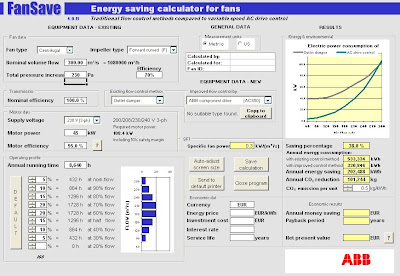
FanSave has been developed by ABB for comparing AC drive control against traditional flow control methods in fans and estimate savings you can achieve by replacing outlet damper, inlet vane or pitch control methods with VSC. Similarly FanSave provides financial and environmental indicator for justification.
Try it out and share your experience with many others here...
Related Post
Try it out and share your experience with many others here...
Download FanSave (Click here)
Download FanSave Operating manual (Click here)
Related Post
- Quatitatively compare Variable Speed Control (VSC) with Conventional Flow Control in Pumping system
- Variable Frequency Drive (VFD) helps in Many Aspects
- Pump Pressure Versus Head
- Why Centrifugal pump NPSH required increases with flow ?
- Tips for Centrifugal Pump
- Consider energy saving by optimizing the pump control
Labels: Energy, Environment, Fan
Thursday, March 27, 2008

Lately, there was a study to minimizing energy consumption and increase life cycle profit for a plant. One of the measures has been identified was to apply Variable Speed Control (VSC) using Variable Speed Drive (VSD). Recent post in Variable Frequency Drive (VFD) helps in Many Aspects (click here), you should be able to aware the benefits of using VSD qualitatively.
In many event, qualitative justification is not 100% convincing and client is always requested detail quantitative justification. Thus, most financial indicators such as life cycle cost, payback period, NPV, IRR, etc shall be estimated to justify if VSC is really make sense to persuade compare to conventional control method. One of the quick way is use a tool, PumpSave, to provide a quick estimation and indication.

What is PumpSave ?
PumpSave is a tool developed by ABB to enables you to estimate energy (money) saving when apply Variable Speed Control (VSC) compare to traditional control such as throttling control, On/Off control and Hydraulic control. In addition, it provides financial indicators (e.g. Payback period, annual saving, NPV, etc) to assess the benefits of adopting Variable Speed Control (VSC).
Simple Operation Steps
It is rather simple to use. With the following actions :
Simple Operation Steps
It is rather simple to use. With the following actions :
- Fill in System and Process parameters
- Fill in intended motor rating and operating profile parameters
Download PumpSave (Click here)Related Post
Download PumpSave Operating manual (Click here)
- Variable Frequency Drive (VFD) helps in Many Aspects
- Pump Pressure Versus Head
- Why Centrifugal pump NPSH required increases with flow ?
- Tips for Centrifugal Pump
- Rule-of-thumb For Minimum Flow Recycle
- Consider energy saving by optimizing the pump control
Labels: Energy, Environment, Pump
Wednesday, March 26, 2008
Display problem ? Click HERE
In the recent project, one the philosophy or principle adopted and implemented was As - Low - As - Reasonable - Practical (ALARP). This has seriously extended to the preservation of environment from pollution and minimizing human interferences. There are several methods proposed and implemented. One of those is use of Variable Frequency Drive in electrical motors for fan, pump, compressor, etc.
How variable frequency drive helps in preservation of environment from pollution and minimizing human interferences ?
Energy saving
Throttling is one of common mean for flow regulation during turndown. This method is simple and low material cost. However, throttling process is serious energy consumer and it done produce useful work. In additional it generate inefficiency, heat, noise, vibration, etc. VFD may be used for flow regulation purpose. Simple affinity law would advise the the relationship of speed and flow. Low speed results low flow and with this it regulate the flow. At low speed, less energy is consumed. As an example, flow reduce from 100% to 80%, power@80% will be 51% of power @ 100%.
Optimum Efficiency reduce energy consumption
VFD can improve the efficiency of motor-driven equipment by matching speed to changing load requirements. By VFD, it can almost constantly maintain a high motor efficiency while carry out flow regulation.
Increase Mechanical Device LifeSpan
As most motor-driven equipment is designed to Best-Efficiency-Point (BE). By maintaining the operating curve close to BEP, the mechanical device life span would be significantly extended.
Reduce Maintenance Cost
Longer lifespan implies longer life for bearing and motors and hence reduce maintenance costs.
Noise & Vibration
Motor operate at constant high speed and throttling process will continuously generate noise and vibration from turndown to design capacity operation. However, using VFD, reducing motor speed and eliminate throttling process would significantly decrease noise and vibration.
Power Surge
Conventionally motor for pump start-up will be equipped with mechanical starter. This power supply system will experience power surge whenever the motor is started-up. Of course soft-starter is one of the solution. Using VFD will eliminate initial power surge.
Increase Production Flexibility
Using VFD, the speed can be very low and hence the turndown. This seriously increase plant production flexibility.
Minimize Water Hammer Potential
Motor with VFD, the ramped up of speed can be controlled and this potentially minimizing water hammer in liquid system start-up. Similarly, controlled ramped down of speed can also minimizing check valve slamming.
Easy Process Control
Motor with VFD function, it can simply process control and increase flexibility in control as well as increase system turndown capability.
Nowadays, energy saving and preserve environment is the major and important element in new and debottlenecking plant implementation. VFD is one of the hot choice for most project. Why not consider to use ?
Related Post
- Estimate Saving with Variable Speed Control (VSC) compare to other Control Method for FANs
- Quatitatively compare Variable Speed Control (VSC) with Conventional Flow Control in Pumping system
- Consider energy saving by optimizing the pump control
- Do not under estimate pump energy cost and FREE Optimization tool for better Life cycle cost
- Restrcition Orifice Used in Many Applications in Different Manners
Labels: Energy, Environment, Pump
Tuesday, March 25, 2008

A vapor-liquid-liquid separation is rather common in offshore oil and gas facilities. Generally separator with boot is preferred for low heavy liquid percentage in the mixtures. What are the factors you shall consider so that you select a separator with boot.
i) Material cost for separator with boot compare to separator with weir is lower. This is in generally perspective but there are exceptional case. It is pretty hard to provides a simple rule of thumb in general for all services. Nevertheless, Bill Svrcek et. al (1994) has indicated that a boot may be selected if the heavy phase is 15-20wt%. This could be a quick goby for a pre-selection during early engineering phase, however, it is always encourage optimization.ii) Boot fabrication required hole drilling at the bottom of horizontal vessel, installation of reinforcement ring around the the boot-vessel connection and additional weldings around the connection. This signify the fabrication is rather complicated and increases the fabrication cost. Thus, combination of material and fabrication cost, total cost for a separator with boot may be higher than a separator with internal weir.
iii) Overall separator size would be one of the factor to be considered. It is not much cost benefits by selecting a separator with boot for rather small separator.iv) Cost for space or overhead. Separator with boot may results small vessel and save installation cross section area. This potentially save cost on the foot print. However, it impose additional cost for overhead. For onshore facilities, normally head room is not a an issue in most cases, however head room could be major cost factor for offshore installation.
v) Separator with boot will result lesser inventory in the separator and this will reduce risk (inventory associated) in this installation.vi) Separator with boot is having lesser weight (material and inventory) and this will reduce cost for vessel support. This is pretty attractive for large separator.vii) For light and heavy liquid separation with very similar density e.g. heavy crude (typical ~900 kg/m3) and produced water (~1030 kg/m3), it could leads interface controllability problem if insufficient margin is provided. Separator with boot would increases the vertical length and increases the controllability of interface.viii) Normally there is a optimum diameter for Separator with boot installation (i.e. boot diameter is 2/3 maximum of separator diameter). The limitation of the boot diameter over separator diameter may be a major determining factor. One process engineer shall not ignore this mechanical constraints.ix) As there is boot diameter limitation, increase boot length is the only direction to increase interface controllability. Extended boot length is not really cost effective as all other cost factor increase.
x) Boot installation will results more vessel cutting and more welding compare to internal weir. This will induce higher risk to be managed.xi) Boot once it is constructed, it is fixed and you have no way to revamp if you wish to. However, a weir installation still can be changed (especially removable weir) after it's fabricated or in operation. The weir height can be changed/adjusted as operator wish. This increases flexibility on made-good for uncertain fluid characteristic.
There is no fix rule for the selection of separator with boot in generally. What do you think ?
Related Post
Related Post
Labels: Separator
Display problem ? Click HERE
 When we watch combat movie, sometime we noticed that the solder in the movie wear a "power shirt" which able to generate electricity to power small electronic devices for soldiers in the field. Now this no long a story. But it is true story...Again this one of the break-through in nano technology ...
Zhong Lin Wang, a Regents professor in the School of Materials Science and Engineering at the Georgia Institute of Technology stated that pairs of textile fibers covered with zinc oxide nanowires can generate electrical current using the piezoelectric effect. Combining current flow from many fiber pairs woven into a shirt or jacket could allow the wearer’s body movement to power a range of portable electronic devices. The fibers could also be woven into curtains, tents or other structures to capture energy from wind motion, sound vibration or other mechanical energy. Read more here...
Related Topic
- Nanowire battery... High Potential of Replacing Lithium Battery
- Nanowerk - NanoTech News & Database Center
- Nano Technology - Revolution in Material Selection
- Design fault in Hydrogen Attack of Residue Hydrodesulfurrization
Labels: Technology
Monday, March 24, 2008
Saturday, March 22, 2008

A pressure relief valve (PRV) in "Ready-to-operate" mode and "relieving" mode during plant operation will expose to different type of pressure. "Ready-to-operate" mode is the PRV's disc keeping PRV in closed position when inlet pressure (Pi) is lower than or equal to PRV set pressure (Ps). "Relieving" mode is PRV disc away from seat allowing fluid passing the PRV valve nozzle when the inlet pressure (Pi) is higher than PRV set pressure (Ps).
Defintion of "backpressure"
As PRV may be in Ready-to-operate and Relieving mode, the "backpressure" exist at different modes will vary. In many event, understanding of this "backpressure" creates a lot of confusion among engineers in operation, design, vendor, manufacturer, etc. It is important to make the defintion clear prior to any discussion.
Superimposed backpressure is the static pressure that exists at the outlet of a pressure relief device (PRD) at the time the device is required to operate ("Ready-to-operate" mode). Superimposed backpressure is the result of pressure in the discharge system coming from other sources i.e. Pressure control valve (PCV), pressure relief valve (PRV), etc. Superimposed backpressure may be constant or variable.
Built-up backpressure is the increase in pressure at the outlet of a pressure relief device that develops as a result of flow after the pressure relief device (PRD) opens ("relieving" mode).
Backpressure is the pressure that exists at the outlet of a pressure relief device (PRD) as a result of the pressure in the PRD discharge system. Backpressure is pressure result of both superimposed backpressure caused by other sources and built-up backpressure due to the relief flow during "relieving" mode. Backpressure is the sum of the superimposed and built-up backpressures.
How "backpressure" affect Conventional PRV ?
"Backpressure" will affect the performance of a Conventional spring loaded Pressure Relief Valve (PRV). "Backpressure" in quotation is common name which includes Backpressure, Superinposed backpressure and built-up backpressure. How "backpressure" affect Spring loaded PRV ? Infact, there are at least three aspects a "backpressure" affecting a conventional spring loaded PRV.
i) Maximum allowable accumulated pressure of protected vessel.
A pressure contained vessel made from any pressure vessel code (e.g. ASME VIII div 2), a PRV shall be provided to protect the vessel from overpressure. Per ASME code, maximum allowable accumulated overpressure is 10% of it maximum allowable working pressure (MAWP). A PRV is normally set at the MAWP (typically). In this case a conventional PRV maximum allowable built-up backpressure shall be 10% of set pressure.
A conventional type PSV protecting a pressure vessel with maximum allowable overpressure of 10% MAWP and exposed to built-up back pressure higher than 10% of MAWP, (e.g. 15% of MAWP) it will results higher accumulated pressure in the vessel (i.e. 115% of MAWP) and exceeded the maximum allowable working pressure (MAWP) with 10% allowable overpressure. Thus one shall always remember that built-up back pressure of conventional spring loaded PRV shall always equal or lower than maximum allowable overpressure.
ii) PRV Capacity
Increased in backpressure (total of superimposed and built-up) below 10% of set pressure is typically does not affect the conventional PRV relieving capacity. As it exceeded 10% of set pressure, the conventional PRV relieving capacity will reduce significantly. See following image.

iii) PRV Stability
Backpressure (total of superimposed and built-up) also affecting the stability of PRV. This can be seen from the study carried out by Thornton (1979) followed by Sterland (1984) and Lai (1989) has shown that a PRV may experience chatting and instability operation when the backpressure is exceeded 10% of set pressure for conventional spring loaded PRV. See the following image.
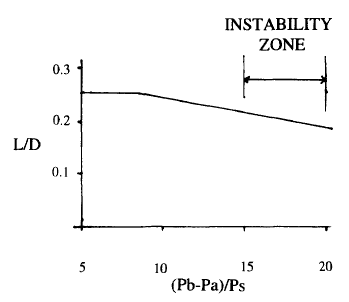
The definition are as follow :
L = Lift of disc
D = Diameter of Inlet Bore
Pb = Absolute Back pressure
Pa = Atmospheric pressure
Pb-Pa = Gauge Back pressure
Ps = Gauge set pressure
Above has briefly discussed the impact of backpressure to a conventional Spring loaded PRV. Do you aware of any other impact ?
Updated : March 02, 2008
Related Post
A conventional type PSV protecting a pressure vessel with maximum allowable overpressure of 10% MAWP and exposed to built-up back pressure higher than 10% of MAWP, (e.g. 15% of MAWP) it will results higher accumulated pressure in the vessel (i.e. 115% of MAWP) and exceeded the maximum allowable working pressure (MAWP) with 10% allowable overpressure. Thus one shall always remember that built-up back pressure of conventional spring loaded PRV shall always equal or lower than maximum allowable overpressure.
ii) PRV Capacity
Increased in backpressure (total of superimposed and built-up) below 10% of set pressure is typically does not affect the conventional PRV relieving capacity. As it exceeded 10% of set pressure, the conventional PRV relieving capacity will reduce significantly. See following image.

iii) PRV Stability
Backpressure (total of superimposed and built-up) also affecting the stability of PRV. This can be seen from the study carried out by Thornton (1979) followed by Sterland (1984) and Lai (1989) has shown that a PRV may experience chatting and instability operation when the backpressure is exceeded 10% of set pressure for conventional spring loaded PRV. See the following image.
The definition are as follow :
L = Lift of disc
D = Diameter of Inlet Bore
Pb = Absolute Back pressure
Pa = Atmospheric pressure
Pb-Pa = Gauge Back pressure
Ps = Gauge set pressure
Above has briefly discussed the impact of backpressure to a conventional Spring loaded PRV. Do you aware of any other impact ?
Updated : March 02, 2008
Related Post
- Useful Documents Related to Pressure Relief Valve (PRV) - Part 3
- Useful Documents Related to Pressure Relief Valve (PRV) - Part 2
- Useful Documents Related to Pressure Relief Valve (PRV) - Part 1
- Should we consider JET FIRE for Pressure Relief Valve (PSV) load determination ?
- Should we install Butterfly valve for Pressure Relief Valve (PSV) isolation ?
- ERRATA - API Std 521, Pressure Relieving and Depressuring Systems
- Discussion on ISENTROPIC and ISENTHALPIC process via Relief Valve
- Use of conventional type PSV with back pressure exceeded 10% set pressure
Labels: Pressure Relief Device
Friday, March 21, 2008
Display problem ? Click HERE
One man accidentally press the emergency push button and initiated the inflation...
Can you imagine if this man doing the same thing in your plant ?
BE ALERT !
Similar Post
- Blast rocks Texas oil refinery
- Petrol Kiosk - Some Thought and Advices...
- Design fault in Hydrogen Attack of Residue Hydrodesulfurrization
Labels: Accident
Wednesday, March 19, 2008
Display problem ? Click HERE
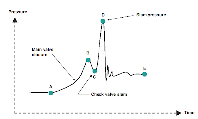
Check valve slam is one of the common problem encounter in rotating equipment discharge e.g pump, compressor, etc. As mentioned in earlier post "How to Select a Check Valve (NRV) Quantitatively ?" one of the requirement is for a "good" check valve is non-slam characteristic.
For a pumping system with a check valve installed on the discharge, whenever the pump is shut, reverse flow is formed quickly and approaching check valve. One of the requirement to avoid check valve slam is the check valve shall be closed faster than the reverse flow acting on the disc. You may the following animation and see how a check valve with the disc closure is faster than the reverse flow and avoid damage of check valve and severe surge pressure.
As the closure of valve disc is affected by few factor such as disc travel distance, reverse flow travel length, etc. How should you predict if a check valve would experience slam and severe surge ?
A methodology for predicting check valve slam is one of the article you may read to identify if a selected check valve would experience slam during closure time.
Related Post
Courtesy of DFT (click to visit)
As the closure of valve disc is affected by few factor such as disc travel distance, reverse flow travel length, etc. How should you predict if a check valve would experience slam and severe surge ?
A methodology for predicting check valve slam is one of the article you may read to identify if a selected check valve would experience slam during closure time.
Related Post
- How to Select a Check Valve (NRV) Quantitatively ?
- Why Redundant NRV in Series within a Line ?
- Why bypass Non-Return Valve (NRV) ?
- Pump Pressure Versus Head
- Why Centrifugal pump NPSH required increases with flow ?
- Tips for Centrifugal Pump
- Rule-of-thumb For Minimum Flow Recycle
- Restrcition Orifice Used in Many Applications in Different Manners
Monday, March 17, 2008
Display problem ? Click HERE

 Check valves or Non-return valves (NRV) are normally installed in piping to avoid back flow. Rotating equipment such as pump, compressor, etc will always be equipped with NRV(s) on the discharge to avoid back flow when rotating equipment is shut. Back flow creates severe surging to the rotating equipment and potentially damage the equipment. In certain process system, NRV will be employed to avoid contamination, overheating, etc due to back flow.
See the following animation how a dual disc check valve action to avoid back flow.

Courtesy of Goodwin
There are many types of check valve (NRV) available such as ball check valve, lift check valve, swing check valve, wafer check valve, disc check valve, dual disc check valve, tilted disc check valve, etc.
For details discussion on each type of check valves, please check out :
- Check valves or Non-return valves (NRV) - Wikipedia
- Check valve tutorial - Spirax Sarco
Out of many types of check valve, how do you make proper selection to suit your application ? An article by VAL-MATIC entitled "Design and Selection of Check Valve" is available for download. This article presented four (4) criteria which shall be considered for the selection of check valve type. There are :
- non-slam characteristic
- pressure loss
- cost
- application
Comparative rating for each type of check valve have been provided for these criteria (specifically first two technical criteria). These rating will be plotted on a Check Valve Comparative Selection Chart and together budget for final selection.
Related Post
Related Post
- Why Redundant NRV in Series within a Line ?
- Why bypass Non-Return Valve (NRV) ?
- Pump Pressure Versus Head
- Why Centrifugal pump NPSH required increases with flow ?
- Tips for Centrifugal Pump
- Rule-of-thumb For Minimum Flow Recycle
- Restrcition Orifice Used in Many Applications in Different Manners
Sunday, March 16, 2008
Display problem ? Click HERE

Recently Roberto recommended a FREE Control Valve & Safety Valve Sizing program "Prode Valve". This software is not from any control valve or safety valve manufacturer but it is by a software developer.
Following are some features in Prode Valve :
All the calculation model following international procedures such as ISA S75.01,IEC 534.8.3 / IEC 534.8.4, API RP 520 / 521, ASME, ANSI and ISO 4126. However, Prode Valves includes customizable archives with manufacturer's models, product's specifications and commercial codes.
Prode Valves has built-in design, rating and selection of control, safety and relief valves features and it can automatically identify the most suitable product and fills in all detailing specifications with built-in manufacturer database.
Apart, it integrates with Prode Properties which adds the benefits of a rigorous thermodynamic framework for calculating equilibria and transport properties of pure fluids and mixtures.
Prode Valve looks very interesting software. Have you ever used Prode Valve ? How you rate this Prode Valve ? Why not share you experiences in comments column ?
Related Topic
Following are some features in Prode Valve :
All the calculation model following international procedures such as ISA S75.01,IEC 534.8.3 / IEC 534.8.4, API RP 520 / 521, ASME, ANSI and ISO 4126. However, Prode Valves includes customizable archives with manufacturer's models, product's specifications and commercial codes.
Prode Valves has built-in design, rating and selection of control, safety and relief valves features and it can automatically identify the most suitable product and fills in all detailing specifications with built-in manufacturer database.
Apart, it integrates with Prode Properties which adds the benefits of a rigorous thermodynamic framework for calculating equilibria and transport properties of pure fluids and mixtures.
- Adiabatic, isentropic flash operations required by multiphase methods as homogeneous equilibrium (HEM) Omega method, homogeneous nonequilibrium (HNE) etc.
- Equilibria (isothermal flash operations) and transport properties
- Gas ( vapor ) , liquid, two-phases properties.
- User defined library (only a few constants required to define a generic fluid)
Download Prode Valve Software - (Click HERE) ...
Download Prode Properties Software - (Click HERE) ...
Download Prode Properties Manual - Click HERE) ...
Prode Valve looks very interesting software. Have you ever used Prode Valve ? How you rate this Prode Valve ? Why not share you experiences in comments column ?
Related Topic
Labels: Control valve
Saturday, March 15, 2008

In the recent project that i have worked on, there was a evaporative cooling tower in this project. The cooling water supplying cooling water to entire plant. One the main activities is to conduct water material balance around the cooling tower. For background theory about the cooling tower and water balance around cooling tower, may refer to GPSA chapter 11 or Wet cooling tower material balance.

The water material for cooling tower has been programed in EXCEL for quick determination of blowdown and make-up water flow. If you are interested to try it out, you may click here to download for your own use. If you have any comment or improvement to this EXCEL sheet, please do not hesitate drop me an email...
DOWNLOAD
Related Topic
- Cooling Tower Thermal Design Manual
- Useful Documents Related to Cooling Tower
- Useful Documents Related to Control Valve
- Useful Documents Related to Pressure Relief Valve (PRV) - Part 1
- How much heat removal by natural convection when Air Cooler fan off
- Success story of turbulator in Air Cooled Heat Exchanger
- Heat Transfer Coefficient For Air-Cooled Heat Exchangers
- Air Cooled Heat Exchanger Control using Variable Pitch Fans
- Design of Quiet Air-Cooled Heat Exchangers
Labels: Cooling Tower
Friday, March 14, 2008

If you are professional engineer, fresh engineer or student and working or interested in COOLING TOWER thermal design, "Cooling Tower Thermal Design Manual" one of the FREE e-manual that you shall not miss. It available FREE for browsing and provided by Daeil Aqua, a specialist company in cooling tower design.
Related Topic
This engineering book was prepared for educating the cooling tower engineers of a company in Taiwan. So, this deals with a very specific subjects, which were never written as of now. I prepared the documents so that the engineers can easily understand the cooling tower theory and can make the design program by themselves through the actual examples. All were run on MS Excel and you will see this new approach in computerizing the cooling tower thermal design. You can download all the examples through this homepage.It consists of 22 chapters and listed as follow :
The major concern during I study the cooling tower theory was how to computerize the cooling tower theory from the calculation of NTU to the cooling tower performance analysis. If you read this book carefully, you can make any cooling tower design programs by yourself.
Again, this will be a first issue releasing the actual engineering approach of cooling tower with the examples in the world. If any questions on this issue, please send your mail to me.
Preface to Fifth EditionThis e-manual is very comprehensive. Take a look at Cooling Tower Thermal Design Manual.
Chapter 1. Psychrometrics
Chapter 2. Heat & Mass Transfer Fundamentals
Chapter 3. Tower Demand & Characteristic Curves
Chapter 4. Cooling Tower Performance Variables
Chapter 5. Consideration of By-pass Wall Water
Chapter 6. Pressure Drops in Cooling Tower
Chapter 7. Velocity Recovery at Fan Stack
Chapter 8. Motor Power Sizing
Chapter 9. Fan Components Sizing
Chapter 10. Air-Water Distribution System Design
Chapter 11. Recirculation of Exit Air
Chapter 12. Evaporation
Chapter 13. Estimation of Actual Cold Water Temperature
Chapter 14. Determination of L/G
Chapter 15. Compare of Tower Performance at Sea Level and Altitude
Chapter 16. Evaluation of Tower Performance at Design Off Design
Chapter 17. Plotting of Tower Performance Curves
Chapter 18. Estimation of Air Flow at No-Load Condition
Chapter 19. Determination of Pumping Head
Chapter 20. Determination of Line Voltage Drop
Chapter 21. Calculation of Tower Capability by Tower Characteristic Curve
Chapter 22. Calculation of Tower Capability by Tower Performance Curve
Related Topic
- Useful Documents Related to Cooling Tower
- Useful Documents Related to Control Valve
- Useful Documents Related to Pressure Relief Valve (PRV) - Part 1
- How much heat removal by natural convection when Air Cooler fan off
- Success story of turbulator in Air Cooled Heat Exchanger
- Heat Transfer Coefficient For Air-Cooled Heat Exchangers
- Air Cooled Heat Exchanger Control using Variable Pitch Fans
- Design of Quiet Air-Cooled Heat Exchangers
Labels: Cooling Tower, Heat Exchanger
Thursday, March 13, 2008
Display problem ? Click HERE

Simple update to IEM members and Student in Malaysia, this coming 17th March 2008, there will a talk on
"ENGINEERING EDUCATION IN UNITED KINGDOM"
by Professor Ashok K Kochhar FREng
& Dr Richard H Scott
& Dr Richard H Scott
In this presentation, the life of an engineering student will be discussed from application to an engineering course through to graduation. The talk will consider the significance of the offer, the features of the courses, typical course structures and student life. It will address the differences between the branches of engineering. The talk will be based on the experience of the Sterling group and engineering education in the UK. It is a general presentation and will not be specifically promoting the University of the Sterling lecturer giving the presentation
Venue : Conference Hall, 2nd Floor, Bangunan Ingenieur, Petaling Jaya
Time : 2.20 pm - 3.45 pm
Organizer : Standing committee of Activities, IEM.
If you are interested, click HERE.
Why Study Engineering?
Engineering is above all about adding value through realisation of technological progress. Engineers and engineering make a major impact in the day-to-day lives of most of us. Engineering qualifications and experience are a foundation for many different careers.
Read more click here.
Read more click here.
Why Study in UK?
UK qualifications are recognized and respected throughout the world. Your UK qualification will be a strong foundation for building your future, boosting your career and prospects for a higher salary. Quality standards for UK institutions are among the best in the world.
Read more click here.
Read more click here.
Engineering Education Scheme (England)
The Engineering Education Scheme (England) is an EDT Programme which links teams of four Year 12 students and their teacher with local companies to work on real scientific, engineering and technological problems. Click here to find out more about the Engineering Education Scheme (England).
