Thursday, October 25, 2007
High pressure and moderate/low temperature operation are common in oil and gas industry. High pressure system with large vessels will lead to large inventory and it significantly increases hazardous level to personnel and assets. Thus, API Std 521 has stated clearly and requested plant emergency response system to depressurize the system from it maximum operating pressure to 50% of it design pressure or 6.9 barg, whichever is lower within 15 minutes. The intention is to evacuate the inventory within an acceptable time limit to minimize risk of secondary hazard to personnel / assets and provides sufficient time for personnel evacuation.
Depressurization study is one of the mandatory studies in oil and gas for long time. Thus process simulator common used in oil & gas such as HYSYS, PRO-VISION, etc have built-in depressuring module which specifically sued for depressurization study. HYSYS has been in the market for more than 15 years and it is well accepted by many users as it commonly known with its “real time” information and user friendly interface. One of section within the depressuring unit where user needs to provide information is the depressuring valve parameter page. The valve parameter page is basically to define the characteristic and vapor flow equation of depressuring device. Users are free to choose those seven (6) vapor flow equations (built-in), There are :
Depressurization study is one of the mandatory studies in oil and gas for long time. Thus process simulator common used in oil & gas such as HYSYS, PRO-VISION, etc have built-in depressuring module which specifically sued for depressurization study. HYSYS has been in the market for more than 15 years and it is well accepted by many users as it commonly known with its “real time” information and user friendly interface. One of section within the depressuring unit where user needs to provide information is the depressuring valve parameter page. The valve parameter page is basically to define the characteristic and vapor flow equation of depressuring device. Users are free to choose those seven (6) vapor flow equations (built-in), There are :
- Fisher
- Masoneilan
- Relief valve
- Supersonic
- Subsonic
- General
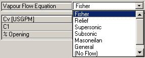
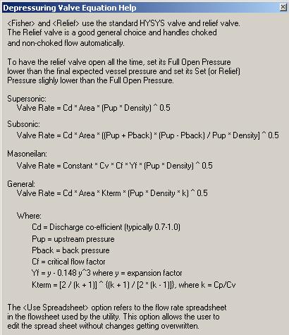
HYSYS default is [Fisher]. User may view the equations used for each of them by clicking the “Valve Equation Help…” button. See following image.
Out of 6 vapor flow equations, which equation shall be chosen and applied ?
HYSYS recommends to used [Fisher] and [Relief] as these equations are more advanced than other valve equation. No doubt these equations are established and well accepted by many users. How shall these equations be applied in different kind of systems ?
In my point of view, [Fisher] and equations will be used when controlled depressuring system. Common controlled depressuring application are depressuring of compressor and Mole-Sieve bed. It is very common the manufacturer of this equipment impose maximum pressure drop-rate (kPa/min) to protect their equipment. User may needs to selected a good control valves to limit the maximum pressure drop-rate whilst meeting maximum depressuring time limit of 15 minutes.
For non-controlled depressuring system, other equations such as may be used. equation is recommended by HYSYS and can be used by setting the set pressure lower the FULL OPEN pressure (REMEMBER : Both setting shall be lower than the maximum expected pressure. Otherwise the valve will not “open”). I guess the main issue here is to provide the discharge coefficient (Kd) for orifice. Personally there may be some document out there which has recommended what type of Kd factor to be used. If any of user aware of it, please share in the comments column.
equation basically is a derivation from the equation by considering Kterm and k equal as unity. This equation may be used in non-controlled depressuring system and it is for critical flow condition where backpressure is lower than system pressure. User may use this equation if the fluid characteristic is not well defined. User shall take note that there is a possibility where initial depressurization will be in critical flow condition and towards the end, backpressure may be exceeded the critical pressure. This will result some level of inaccuracy. This is very unlikely event and generally it is ignored.
equation is an equation which common used in non-controlled depressuring system and to handle subcritical flow system (backpressure higher than system pressure). This is the only equation built into HYSYS which can handle subcritical condition (as far as I aware but I guess and may be capable). HYSYS has not documented this. Thus it is not recommended to use.
[General] equation is a well accepted equation which has been extracted from PERRY’s Chemical Engineering Handbook. The only parameters user required to input are the orifice Discharge Coefficient (Cd) and Orifice area (A). As in most of the case, a square-edged restriction orifice is applied for depressuring, (downstream of Blowdown valve, BDV), the discharge coefficient (Cd) is well defined in . See following image.
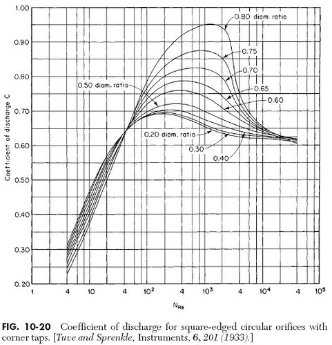
Generally the Reynolds number at the orifice throat is higher than 10,000, thus the Discharge coefficient is in the range of 0.6 to 0.65. Beware that HYSYS has recommended the used of 0.7 to 1.0. This may be true when the Reynolds number is in the range of 100 to 10,000. User shall always check at the end of study. Personally I would recommend to us 0.6 and reconfirm with Reynolds Number check by end of run. One shall remember this equation is applicable to Critical flow condition only. As in most cases, plant emergency depressuring will be critical flow, i am recommending to use this equation when you are dealing with non-controlled depressuring.
You comments and advices are welcome.
HYSYS recommends to used [Fisher]
In my point of view,
For non-controlled depressuring system, other equations such as
Generally the Reynolds number at the orifice throat is higher than 10,000, thus the Discharge coefficient is in the range of 0.6 to 0.65. Beware that HYSYS has recommended the used of 0.7 to 1.0. This may be true when the Reynolds number is in the range of 100 to 10,000. User shall always check at the end of study. Personally I would recommend to us 0.6 and reconfirm with Reynolds Number check by end of run. One shall remember this
You comments and advices are welcome.
Further Reading :
Labels: Depressurization, Emergency Shutdown, HYSYS
Tuesday, October 23, 2007

I have been participating discussion in some major Chemical and Process Engineering forums. There are many Chemical Engineering related topics being discussed in these forums. The discussed topics covers unit operation, thermodynamic, material, Process safety, etc. Personally, i have learned a lot of practical experience, new technology, common mistake to be avoided, etc in these forums. Practising engineer in Chemical & Process, Oil & Gas, Petrochemical, Refinery, and other related field, regardless you are in design & engineering, Operation & maintenance and research & development, you are always encourage to participate in these forums.
Low quality question and its impact
Based on my past experience in forum, i have noticed many professional engineers and students posted a lot of questions in these forum. Recently i found that many question are non-forum related, asking question without providing basic background information, some with very good background information but no clear problem statement, etc and this ended up many Professional engineers either raise question on question or ignore them. This really resulted major impact to both Professional engineers and young engineers (newbies). Professional engineers will start to lose their interest in answering those "low quality question" as they ignore most of the question. Soon they will lose their interest logging into the forum. Similarly those young engineers (newbies) posted a lot of question (low quality question) did not get any responses and answers from any Professional engineers or criticism from Professional engineers on the quality of question, soon they also lose their interest in the forum. Consequently less and less people in the forum and possibly close down of forum.
What you needs to do in order to raise a high quality question (post) ?
There are few elements shall form a high quality post :
i) Clear Topic / Subject
Generally a post will have it main topic and subject description. The topic shall consist of keyword of the post content. For example a post ask about the methodology in estimating slug size for slug catcher design, a good topic may be "Slugcatcher design" and subject description may be "How to estimate slug size ?". Any people read the topic and subject, he/she will have a simple and broad idea what the post would be and related to. Those professional engineers who are expert in same field will open the post, review and provide necessary response. You may imagine if someone post a question with topic and subject such as "Help me Please !", "Need your help", etc. These type of topic / subject will not generate any interest of professional. They will spent their time to open these kind of question one after another as they though it is not related to their field.
A good topic and subject will ease for search and references by any engineers / students in the future. It is also ease the originator and responder locate them in the future.
ii) Simple introduction
A good post shall contain a good and simple introduction. The intention is to describe the background information of the topic and subject so that reader understand the background. It may contains :
- Brief description of your system, operation, etc
- References, drawings, sketches, etc to further enhance understanding.
You are also encourage to submit an editable file such as EXCEL spreadsheet, WORD document, etc so that the responder can provides input into the editable file and resubmit it. This helps to keep track of the history, discussion, knowledge, etc.
One must remember, this introduction shall be BRIEF & SIMPLE. Professional engineers are fact finder and tends to ignore long story.
iii) Simple content & situation
Next would be providing a simple content and situation. You must provide simple situation description of problem you encountered, how it happen, what's your experiences, etc in order to inform your potential responder the situation and problem. This is the place where you must clear define your problem.
Apart you must provides required basic parameters related to your question. All information related to your system, situation, problem, etc should be presented here. Your potential responder request these information to understand those information used and they can base on this information to do some calculation, estimation, search, fact findings, etc and to work out the responses.
You shall only provide sufficient information (required information only but not those non-related / required information) to avoid potential responder tired of figuring which information to use.
Again these information should be SIMPLE and SUFFICIENT.
iv) Ask specific question
Now come to the main part of your post. You have to ask clear question. I have noticed many posts come with good introduction and problem, however, no question being raised. The responder will scratch the head as they do not know what he/she shall respond to.
The question shall
- shall raise specific question related to your topic
- shall provide your own though in the question, how you will approach the problem (if you know), etc
- shall not ask something non related to your topic / subject / content / background
One of the major elements you shall present here is you shall be able to demonstrate to your potential responder that you have done some background works and you have come to no answer, no conclusion, no confident on your findings, etc. Professional engineers always like to see people have done their homework before they raise the question. Remember, your potential responder (professional engineers) are mostly (99%) are on voluntary basis. They are not paid to answer question in the forum. They have no obligation to do your homework.
v) Spell and Grammar check
After you have completed your post, before post it, you shall conduct spell and grammar check. This is a non-technical related but essential. May professional engineers will feel uneasy and tends to stop reading on the post once they found the post contain too much spelling and grammar mistake. Mis-spell words and wrong grammar may lead to misunderstanding of the original content.
v) Forum guideline
Last but not least, you shall read the Forum guideline before any posting. Some forum have very straight policies. Any violation regardless of whether you have done it without knowing it or careless, you may be permanently banned from the forum.
With above simple guidelines, wish you will benefits from the post and raise a clear and high quality question in the forum.
Further Reading :
Labels: General
Monday, October 22, 2007
There are many websites providing FREE information to their users/visitors in recent years. This has made a lot of information available for access and refer with no cost. These websites compile informations and arrange it in the way you can easily access and read. I am sure many of you are more often get information from internet rather than books, journal, etc. Have you ever ask yourself if the provide information is good, correct, reliable, correct and relevant ?
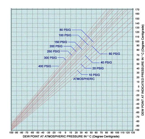
Let take for example, there is a simple Compressed Air Dew Point Chart available HERE for public view. This chart has given a very good tools to the user to convert compressed air dew point @ pressurized condition to dew point @ atmospheric pressure and vice versa. It really a simple but good tools for those process design engineer and plant engineer conversion of compressed air dew point.
Let take for example, there is a simple Compressed Air Dew Point Chart available HERE for public view. This chart has given a very good tools to the user to convert compressed air dew point @ pressurized condition to dew point @ atmospheric pressure and vice versa. It really a simple but good tools for those process design engineer and plant engineer conversion of compressed air dew point.
However, if you really goes in to details of the ATMOSPHERIC line, take the "0" on X-axis, it mean "0 degC dew point at ATMOSPHERIC pressure". If i draw a line straight-up and touch the ATMOSPHERIC line (diagonal red line) and horizontally reach the Y-axis, you will get "2 degC dew point at ATMOSPHERIC pressure". This does not tally between each and other. These happened to others temperature range from -40 degC to 70 degC. See below image.
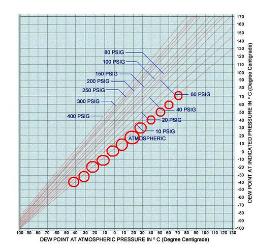
This signified that the graph is incorrect for certain temperature range and this also imply that other lines may create some level of error. If you use the curve without careful, you may risk yourself in making mistake.
This signified that the graph is incorrect for certain temperature range and this also imply that other lines may create some level of error. If you use the curve without careful, you may risk yourself in making mistake.
(This is just an example for continuous education. It does not intended to offense any personal, party and company).
Those anytime you received any new information, first you have to assess how good, correct and reliable of the received information. One of major clue that presently here is use the known facts to verify the information. You may also to cross check with other reliable information e.g Perry Engineering Handbook to verify the information. This way will minimize your risk of making mistake.
If you found some doubt on any information on any website, you are encourage to advise the web owner. With this action, you will avoid more user refer to wrong information if it is really a mistake OR you will learn new knowledge as the web owner will advise you the reasoning behind your doubt.
If you have problem with contacting the web owner, you are always welcome to drop an Email to me.
Labels: Education, General, Learning
Saturday, October 20, 2007
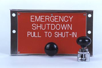
Shutdown Valves (SDV) are common apply in oil and gas production system for safe and proper isolation purpose to minimize escalation of hazardous from one system to another system. General shutdown valve is controlled by a high integrity Emergency Shutdown System (ESDS).
A shutdown valve shall equipped with the following features :
i) Tie Shut Off (TSO)
- Zero/minimum leakage shall be expected for a device act as shutdown valve. Generally a Shutdown valve seat leakage shall pass the seat leakage testing per API 508 and/or ISO 5208.
ii) Firesafe
- shutdown valve is expected to work promptly even though it expose to external fire attacks. thus, shutdown valve body shall be fire rated according to API 607 for soft seated valve or API 6FA for API 6A & API 6D valves or BS 6755 Part 2.
iii) Fast action (From Full Open - Full Close)
- A shutdown valve shall act fast to minimize the escalation of hazards. Generally a quarter ball valve is the excellent device in quick action. As rule of thumb, shutdown valve shall be capable of begin it closing action within 10 seconds of activation, and time taken from Full open to Full Close is within 1-2 seconds per inch of shutdown valve size. However, this shall be compliant to overall safety philosophy. Proper selection and sizing of actuator to ensure above requirements are fulfilled.
iv) Minimum passing (during closing of shutdown valve)
- The feature is required to minimize the potential of overpressure of Low pressure system and spurious trip. A shutdown valve with equal% characteristic (most ball valve will have this feature. However, this shall be confirmed with valve supplier) is preferred type. With equal% characteristic, it can operate with 10% valve closure give 20% flow reduction, 20% closure give 50% closure...the closure of valve is fast and minimize inventory passing.
v) Minimum disturbance / turbulence to process fluid
- This feature is to minimize unnecessary energy lost. Reduced Bore (RB) ball valve having hole in the middle would minimize flow direction change and turbulence. Full Bore (FB) ball valve virtually like a pipe- significantly minimize energy lost.
vi) Fail-safe
- A shutdown valve actuator shall pneumatic/hydraulic fail-safe spring-return type. Generally a shutdown valve failed to close (FC). Electrical driven type shall not be used.
vii) Manual field reset
- A shutdown valve shall be reset manual at field. The operator shall ensure the system is clear and safe and reset on site. No remote reset is allowed.
viii) Clear physical indicator
- Shutdown valve shall be equipped with visible external valve position indicators to provide clear positioning and status of a shutdown valve.
ix) Position switches
Position switches shall be provided on shutdown valve to provide clear positioning and status of a shutdown valve to control room.
x) Partial Stroke Testing of Shutdown Valve
A shutdown valve in critical service e.g. Pipeline outgoing and incoming shutdown valve (ESDV) will required periodically partial stroke testing in order to maintain / increase it reliability, availability & SIL level.
xi) Accumulator
Some shutdown valve may be equipped with accumulator to facilitate valve stroking and /or reopen in the event maloperation.
xii) Second Solenoid valve
Shutdown valve in critical service may be equipped with second solenoid valve to increase reliability and availability.
Above has presented 12 features of shutdown valve. Some operating company may have their additional requirements and limitation on shutdown valve.
Related topics
- ERRATA - API Std 521, Pressure Relieving and Depressuring Systems
- Requirement of overpressure protection devices on system design to PIPING code
- ESD Selection Guide, Metso Automation, Issue 4/2001
- Partial Stroke Testing of Emergency Shutdown Valves, ACM Automation
- Achieving High SIL Ratings with Partial Stroke Testing of Valves, ACM Automation
Labels: Emergency Shutdown, Loss Prevention, Overpressure Protection, Safety
Thursday, October 18, 2007
American Petroleum Petroleum (API) released the API Std 521, Pressure Relieving and Depressuring Systems early of 2007. As usual, there are some mistakes spotted in the this Standard. First errata that i received was dated June 21, 2007. I am a bit outdated. Somehow, i guess there are still many engineers out there (like me...) may not aware of the release of this errata. If you are user of this standard, i strongly urge you to download this errata and make correction to your copy.
If you find anymore mistake or error in this standard, please drop a comments or sent me an Email . I will take the necessary action from there...
If you find anymore mistake or error in this standard, please drop a comments or sent me an Email . I will take the necessary action from there...
Related topics
Labels: Depressurization, Loss Prevention, Pressure Relief Device, Safety
Wednesday, October 17, 2007
In earlier post "Slugging and Slucatcher", there are four types of slugcatcher are generally used to handle intermittent transient slug. First three types, horizontal separator, vertical separator and finger type are referred as common type slugcatcher and many engineering companies have the design & engineering capability of these common type slugcatchers. The last type is Slug Stabiliser which is rather different in term of design, operation and slug handling principle.
Those common type slugcatcher are designed to handling gas-liquid separation during normal operation. They are similar to most of the dual phases separator. The only additional feature built in is the slug handling and liquid holdup storage capability.
Slug Stabiliser is operation is slightly different. Normally it don't works as gas-liquid separator. Normal gas and liquid will flow through the bypass and feed the downstream gas-liquid separator. However, in the event transient slug arrive at slug stabiliser, slug with high momentum will flow across the bypass line while gas is taking the easy route flow into the bypass line. Phase separation occur at the bypass branch when slug approaching the slug stabiliser. Liquid (slug) keep in the loop will be handled after slugging event.

OilPro is one of the proprietary technology owner of Innopipe, a patented Slug Stabiliser. The following article is available from OilPro which describe in detail of basic principle, design and operation of Innopipe.
Related / References :
Those common type slugcatcher are designed to handling gas-liquid separation during normal operation. They are similar to most of the dual phases separator. The only additional feature built in is the slug handling and liquid holdup storage capability.
Slug Stabiliser is operation is slightly different. Normally it don't works as gas-liquid separator. Normal gas and liquid will flow through the bypass and feed the downstream gas-liquid separator. However, in the event transient slug arrive at slug stabiliser, slug with high momentum will flow across the bypass line while gas is taking the easy route flow into the bypass line. Phase separation occur at the bypass branch when slug approaching the slug stabiliser. Liquid (slug) keep in the loop will be handled after slugging event.
OilPro is one of the proprietary technology owner of Innopipe, a patented Slug Stabiliser. The following article is available from OilPro which describe in detail of basic principle, design and operation of Innopipe.
Related / References :
Labels: Slug, Slugcatcher, Slugging
Monday, October 15, 2007
 In my earlier post, "Theme for Blog Action Day - ENVIRONEMENT", OCT 15, 2007 is the Blog Action Day and the theme of the day is ENVIRONMENT. Have we ever ask ourself how much damage we have made to our environment ? I m sure many of us (especially within our Chemical & Process , Oil & Gas communities) are aware of the "contribution" by human to environment and nature. If you are one of them who don't ware of this, i am strong requesting you to take a little of your effort... continue reading...
Environmental issue is one of the hot topic recently and a lot of efforts have been taken / are taking to minimize and slowdown the impact and damage to our environment. You can appreciate this by understand the 2007 Noble prize (Chemistry) winning theme is ENVIRONMENT. Many of us may take this issue easy that this type of "biog" things, we leave it to those who has "big" vision, environmentalist, etc, This is just a "politic" topic and enjoy by many politician. Ultimately giving yourself a statement - Nothing much i can do.
Guys !...take a step backward. There are many things we can do although we are just nothing to anything. Following are something you can do :
- Spread the environment awareness - Blog about it, inform you junior / kits, friend around you. Or minimum inform them to read this post. Or Copy contents of this post to forum, etc and create a link to this post.
- Practise it - if you have not practised any of measures here, please practise at least ONE. If you have practised some, please practise EXTRA one. If you have practise ALL here. Congratulations ! Please provide ONE more extra measure in the comment.
- Segregation of rubbish - Please segregate rubbish into a few categories such as non-biodegradable type (plastic, polymer, etc), biodegradable type (organic stuff, food, etc), reusable/recyclable bottle / aluminum cans, etc.
- Proper Disposal of Electronic waste - Used batteries collect and sent to licensed disposable unit. NOTE : I would like to collect information on this type of collection center throughout the world so that it can be made known to everyone. If you aware any of this unit within you area, please drop me a note (Email) or leave it in comment column.
- Recycle cellphone - Further reading... cellforcash - Recycle Your- Cellphones
- Use Mechanical watch instead of Electric powered watch
- Minimise consumption of packing paper - When you buy stuff in the store, most store will pack your purchased stuff in a plastic beg. f you only buy some light and small stuff, please do not ask for / return the plastic beg to the store owner (NOTE : remember to keep your receipt as proof of purchase.)
- Use rechargeable battery instead of non-recycle type
- Read e-book - Review & comment on the electronic paper instead of hard copy
- Use recycle paper for draft works
Related topic
Labels: Environment, World day
Sunday, October 14, 2007
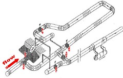
Very basic does not imply obvious...i really like this statement. Very often the answer is very fundamental and basic to us, somehow it always does not obvious to us.
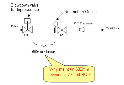
Lets look at the above sketch. It is a typical arrangement for a Blowdown Valve (BDV) with Restriction Orifice (RO) , located downstream of the Blowdown valve. This arrangement typically used to depressurized a system inventory to a safe level within a limited time to minimized catastrophic scenario. Between the Blowdown valve and Restriction orifice, there 600 mm spool piece between them. What the main purpose of this 600mm spool piece ?
Is this spool for straightening and smooth flow ?
Is this spool to avoid secondary choke ?
Guess what ?
Reasoning...Major pressure drop will take place at Restriction Orifice, downstream of Blowdown valve during blowdown. Joule-Thompson (JT) effect results fluid temperature downstream of Restriction Orifice drops below subzero (Less than zero degree Celsius). Latent heat in the piping will transfer to cold fluid and slowly approaching this subzero temperature. The "coldness" will travel back to upstream of Restriction orifice and probably reaches Blowdown valve. It potentially cause the upstream Blowdown valve body temperature drops below subzero as well. Moisture from atmosphere will freeze at the Blowdown valve body and potentially cause the stem stuck at position. Operator may not possible to close the Blowdown valve after blowdown activities and may potentially lead to back flow. Those "general good engineering practice is to locate Restriction orifice, 600mm downstream of Blowdown valve.
Related topics
Labels: Depressurization, Overpressure Protection, Safety
Friday, October 12, 2007
Last month, Zaki from Chemical Engineering World conducted an e-Interview with me. Zaki' s blog provides very informative and interesting subject to his readers. He also the owner of Chemical-Engineering-Forum.com. Thanks to Zaki who has spend his valuable time blog / interview / introduce me to reader to his blog and to the world. Appreciate his effort. You may read about me by clicking this LINK.
Related Topics :
- New Concept of Floating Unit - Part 2
- New Concept of Floating Unit-Part 1
- Floating Gas Refinery Unit
- Launching of Wilhelm Busch
- Gas Processing, NGL Extraction & LPG Fractionation
Thursday, October 11, 2007
(Click photo for better view)


Construction of platform jacket (short cylinder)

(Begin installation of topsite)

(Living quarter installation)


(Construction completion is around the corner)


(Float off & Loadout)


(Sailing...)

(Installed & in Production)
More pictures...Click HERE
More pictures...Click HERE
Related Topics :
- New Concept of Floating Unit-Part 1
- Floating Gas Refinery Unit
- Launching of Wilhelm Busch
- Gas Processing, NGL Extraction & LPG Fractionation
Labels: Floating Unit, Oil and Gas
Wednesday, October 10, 2007
I have seen many Floating Production Storage Offloading (FPSO) either is new build and /or conversion from existing ship. Somehow all FPSO are in rectangle shape with rather sharp head. The other type of Floating Production Unit (FPU) which is in a rather square shape.
The following are some new type of floating platforms. There consist of Floating Accommodation Unit (FAU), Floating Drilling Production Storage Offloading Unit (FDPSOU), Floating Gas Turbine Generator Unit (FGTG) and Floating Mobile Subsea Vehicle Unit (FMSVU).
Floating Accommodation Unit (FAU)

(Click image for better view)
Floating Drilling Production Storage Offloading Unit (FDPSOU)

(Click image for better view)
Floating Gas Turbine Generator Unit (FGTG)
(Click image for better view)
Floating Mobile Subsea Vehicle Unit (FMSVU)
(Click image for better view)
All units are potable and inter-link between each and other. They can be added and relocated according operation demand.Floating Mobile Subsea Vehicle Unit (FMSVU)
(Click image for better view)
These units have been constructed in YANTAI yard, China in 2005. Next post will includes the actual photos of these units.
Related Topics :
Labels: Floating Unit, Oil and Gas
Tuesday, October 9, 2007

Dear all, this coming October 15, a week from today, is Blog Action Day, and the theme of year 2007 is ENVIRONMENT. We, involving in Oil & Gas, Refinery, Petrochemical plant development and operation. We knows there are million of waste gas (those gases aggregate greenhouse effect) discharges to atmosphere. We are slowly destroying our ENVIRONMENT. Of course, many of us are professional and responsible to every creatures in the EARTH. Of course, i know we are trying to our best knowhow to minimize the gas emission...Apart, we should continue our efforts...Raise awareness via blogging is one of the channel.
If you have a blog regardless of what you are blogging about, i would like to invite all of you to participate in celebrating this day.
All you have to do is to post something related to the environment in anyway you likes on Oct 15. You are absolutely FREE on this issue. Example given by the organizer are write anything about environmental which you think is important and carry some meaning to you, gardening, house keeping beach cleaning or neighborhood cleanup...anything story telling which helps to preserve the only EARTH... Podcasting, videobloggong, or photoblogging...ALL are acceptable as long as related to ENVIRONMENT.
Interested ? Register your blog with the 7,000+ other blogs (with 5 million readers!) that are already signed up. Also, see the Blog Action Day blog for more on how bloggers can change the world.
Labels: Environment
Monday, October 8, 2007
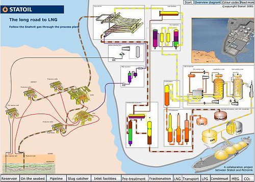
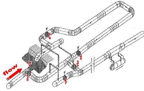
Above image shows a typical flow sheets for oil and gas exploration, Liquefied natural gas (LNG), Liquefied Petroleum Gas (LPG) and condensate production.
General units involved are Oil & gas exploration (sub-sea, top site, onshore), bulk separation, gas treatment prior to Natural Gas Liquid (NGL) extraction, Liquefied Petroleum Gas (LPG) fractionation, condensate stabilization, Carbon Dioxide (CO2) gas compression & reinjection, Mono-Ethylene glycol (MEG) regeneration, etc.
The following flash shows all above in a very simple manner. It is very useful to all engineers who just get involved in Oil & gas business. Click HERE for detail text.
Related Topics :
Labels: Acid Gas Removal, Fractionation, gas processing, Gas Sweethening, Refinery
Sunday, October 7, 2007
In oil & gas field development, interfiled pipelines widely used to transfer well fluid from Satellite wellhead (SW) to Center Processing Platform (CPP) for pretreatment, conditioning and processing. Partial conditioned gas and partial stabilized condensate will then transfer to onshore plant via pipeline for further processing. Byproduct or waste such as produced water, Mercury, sand, etc are generally removed at CPP. Produced and Mercury will be injected back to reservoir for proper disposal. Collected sand which contaminated with hydrocarbon, mercury, etc will be send to onshore for treatment prior to sand filled.
Slugging
Partial conditioned gas and partial stabilized condensate travel through long distance pipeline will experience frictional loss and heat loss to ambient. These results change in equilibrium state and lead to condensate formation for partial conditioned gas and flashing in partial stabilized condensate. Two phase gas-liquid flow along pipeline will leads to unavoidable non-stable operation e.g. slugging flow.
Hydrodynamic Slugs
Shift in equilibrium results liquid formation or flashing and subsequently leads to slug formation, this type of slugs called Hydrodynamic slugs. Apart, there are other way / operation will results slugs formation.
Terrain Induced Slugs
Slug caused by accumulation and periodic pushing of liquid column along pipeline is called Terrain Induced Slugs. This kind of slug generally observed in severe undulation pipeline and low flow operation.
Flow Induced Slugs
Low flow operation leads to liquid accumulation in the seabed. During production ramp-up, high gas flow force liquid holdup in the pipeline towards receiving facilities. Big slug may form if improper operation of ramp-up activities.
Operational Induced Slugs
Pipeline inspection and maintenance is part of the frequent activity for any pipeline. Pigging will be the general activity to carry pipeline inspection and removal of liquid holdup, debris, sand, mercury, etc accumulated in the pipeline. Severe slugging may occurred during pigging if the pigging activity is improperly managed.
As slug approaching receiving facilities, slug size will grow. Large slug arrived at first receiver will seriously overload the liquid handling capacity and may leads to tripping of receiving facilities. Increase liquid handling capacity to handing intermittent large liquid flow may not be cost effective. Thus generally the first receiver will be designed to temporary store the intermittent slug and it will be treated after the slugging period. This receiver generally called Slug catcher.
Slug catcher is a device normally to carry bulk separation and to temporary store big slugs. There are few types of slug catchers have been designed. The following is a listing of types of slug catcher :
a) Horizontal separator type
b) Vertical separator type
c) Finger type
d) Slug Stabilizer type
Type (a) & (b) are essentially same as conventional horizontal and vertical slug catcher but with built-in slug handling capability.

Horizontal type
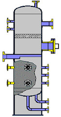
Vertical type
Following images show typical finger type and slug stabilizer type slug catcher :
Finger type
Slug Stabilizer type (Innopipe)
Slug Stabilizer type (Innopipe)
Labels: Separator, Slug, Slugcatcher, Slugging
Wednesday, October 3, 2007
BELIEVE it or NOT ?
Recently i have received a batch of photo from a friend of mine...Huh...I don't really believe what shows in front of me.
The story started with some offshore platform photo which looks old, lack of maintenance & repair works or scenes after typhoon attacked...


As per the source, this happened in one of the PETRONAS platform in EAST Coast of Malaysia ?
Infact, something unbelievable has happened...
CLICK the photos to view bigger pictures...just wanna to create the effects (i hope)...


Infact, something unbelievable has happened...
CLICK the photos to view bigger pictures...just wanna to create the effects (i hope)...
DO YOU BELIEVE ?
